My name is Jurgen Roeland, I live in Belgium and I'm very proud to call myself an aircraft builder. Wish you a warm welcome to my builders blog.
Some people called me nuttzzz. Some people buy a porche when they get into the mid life crisis age. Other people take a second wife. Others get depressed. I decided to start building an airplane. A what ???? Yes, an airplane ! I skipped the phase of building the small plastic versions with glue and paint and went right into the real thing. My time is precious now so let's cut the obvious questions upfront. I heared them too many times already so here is the -mandatory FAQ reading- if you plan to visit my workshop. "You're building an airplane?" : Yes, I am. "A REAL airplane?" : Yes", "In your garage?" : Yes. " "One you can actually fly in?" : Yes! "You can do that?" : Yes!!!
If you look at history, it's been thousands of years that people have dreamed about flight and it's only in the last 100 years that we have now the opportunity to build our own airplanes and fly. The current project work is the results of years of deliberation, evaluation and planning. I took the advice of fellow builders very seriously and so should you. The type I have decided to build is the Van's aircraft, RV-7. I will motivate my choice in one of the subsections of this site. I hope you enjoy following my building adventures and that you will return frequently to check on the progress. The latest activity will always be posted on the main page.
For people that live nearby, feel free to come and have a look. Don't forget to bring a six-pack. The most frequently used lubricant in my workshop is called "Jupiler", bring some as I'm frequently running out of stock.
21/02/26 - Started Bill Lane plenum work - 3h
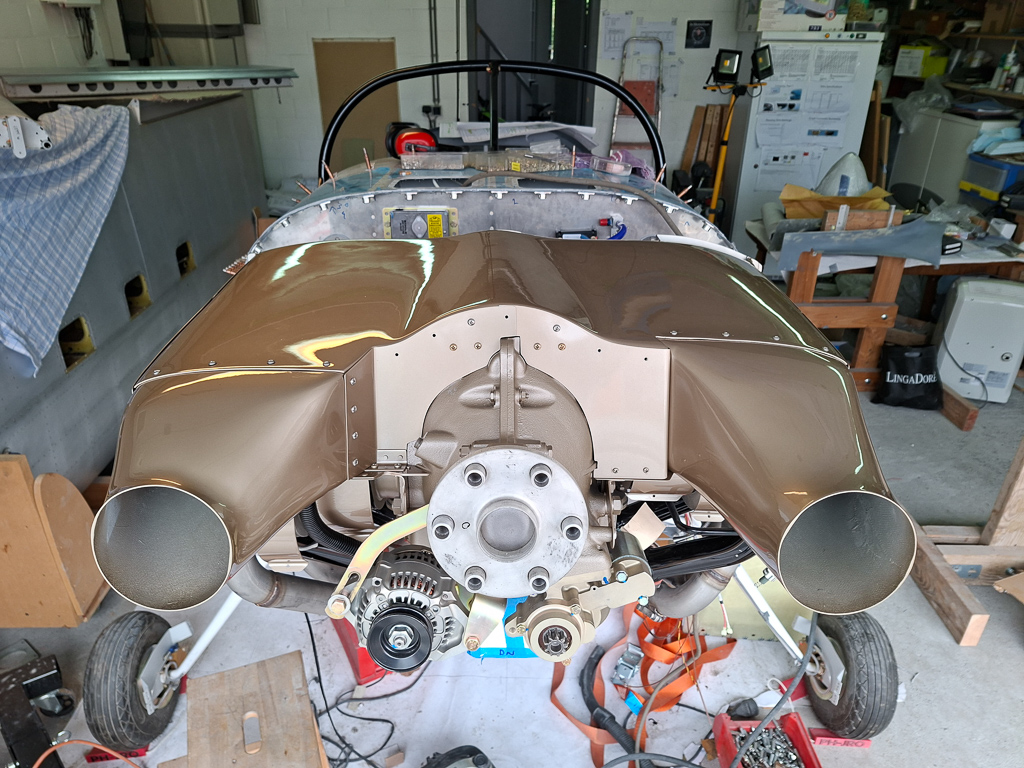
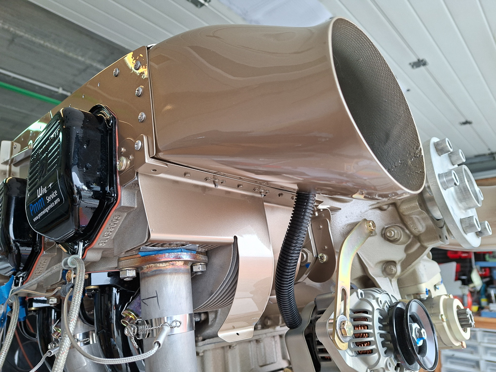
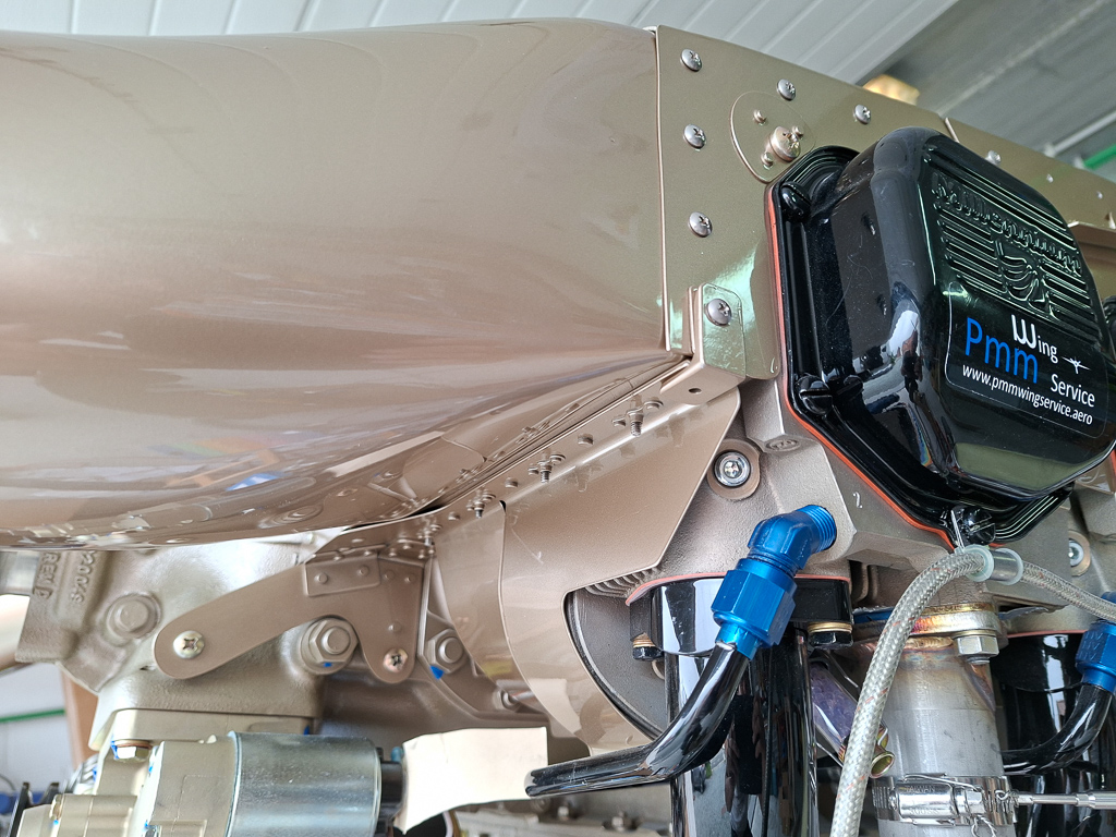
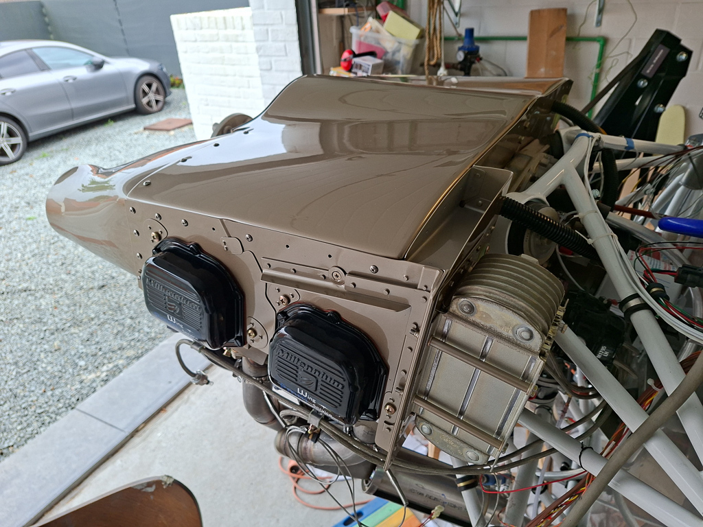
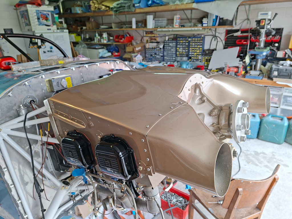
A new episode is starting. As the cowling is fully fitted and the Van’s baffles installed, I decided to take on the installation of the plenum.
This has been a long and expensive crusade.
I had first bought the Sam James plenum. In my naive thinking, I thought the Sam James plenum would be the perfect combination with my Sam James Long Cowl.
The first moment it arrived, I already had doubts about the shape and size of that plenum.
As I started fitting it, I soon found out that it would be way too low over my cylinders. I had already read about builders having to use shorter spark plugs, but what really did it for me was the fact that the plenum would even hit my injector lines on top of the engine.
There is no way to move the plenum upwards, as the diffusers are molded onto the plenum. It caused me many restless nights until a fellow builder from the Netherlands told me he had recently purchased another plenum for his RV-7 because he had been experiencing cooling problems with his RV and the SJ plenum.
The plenum he referred to is called the "Bill Lane Plenum", named after William Lane, who invented and built the first version of this plenum.
The big advantages of this plenum are that:
It is made to be used in combination with the standard Van’s baffle kit.
The diffusers are separated from the plenum roof, which gives you some flexibility during installation.
The diffusers also have a higher up-ramp, which positions the plenum roof higher above the engine, providing much more space over the injector lines and the ignition wires on the spark plugs.
After some research and, to my great surprise, I found out that Bill had sold his moulds to James Aircraft. You can find the link to it here.
I contacted James Aircraft, and they were kind enough to offer me a replacement if I would send back the SJ plenum and pay for the shipping costs of the new one. Getting a box that size back to the USA was rather expensive but in the end it was less expensive than buying the new one. When my replacement plenum arrived, I was very anxious to continue with this part of the build.
Now that I knew what the plenum would look like, I could continue working on the baffles.
First, I made the aluminum spacer, which is a reinforcement piece for the pilot-side rear baffle that holds the oil cooler. Many flying RVs have developed cracks in that corner and have an additional aluminum angle nested in the intersection. I also plan to do that.
Rounded the angle. All this is off course very theoretical as the real height will be determined by the distance from the top cowling which I will measure when I get to install the roof of the plenum.
Next I started modifying the front baffle on the pilot side. The Bill Lane plenum uses epoxy diffusers which ride on the horizontal line of the front baffle. So you can cut off the ramps from the Vans Baffles. Only on the pilot side, you need to keep a small section on the inside. This will be the floor for the pilot side front baffle. I cut it conservatively for now, it will be trimmed down further as I get to fit the front baffle.
On the passenger side front baffle, you can cut off the entire ramp. It's not needed. I did keep a couple of mm's which I will final trim once the diffuser is drilled on. The ramps interfere with the diffuser. You will not be able to position the diffuser with the ramp still in place.
Finally this picture. Learned something new today about my engine. In the center of the rear case sits this port. It is the Tach port or a connection point for a tach meter drive. I had already purchased the UMA tach sensor that mounts on the magneto so I will need to order a cap to cover this port. Andair sells these caps as TC875, "Tachometer cap". Spruce sells it as pn 10-06754. I got mine from PMM wingservice in Belgium.
My magneto's are both old style Champion Slick Magneot's with impulse coupling.
Both mags have the impulse coupling which retards the spark upon start of the engine for easier starting. Usually only 1 magneto has the impulse coupling and in that case the starter swtich needs a jumper placed on the ACS-510-2 starter switch.
This jumper would ground (disable) the magneto without the impulse coupling during start so that they don't work on different timings which could be disastrous for your engine.
In my case it's easy, both have an impulse coupling so both mag's must be active and used during cranking of the engine at startup. No grounding on startup in my case.
That makes the wiring on the ACS-510-2 starter switch also a bit easier.
Some theory first :
A magneto is always hot ! Meaning it's always working and providing a spark when the propellor is turned and the magneto spins.Even with the master switch off...
The magneto works independently from the electric system and provides it's own power. Accidentally spinning the propellor could fire up the engine and cause mortal and disastrous consequences for people in the area of the propellor.
To provide a safety mechanism and disable the magneto when we are in the hangar, we GROUND the magneto's.
This is done by a wire that runs from the starter switch to the P-Lead stud on the magneto. It literally attached the P-lead to the Ground path of the aircraft.
If the magneto is attached to Ground, it is unable to produce a spark and as such cannot fire the engine.
The reason doing this through the ACS-510-2 starter switch is because we need this grounding also during our run-up run on the ground where we test one by one the left and right magneto activity.
When we place the key on L for testing the left magneto, internally in the switch, the right magneto P-lead is grounded and the other way around.
With the starter swtich to OFF, both P-leads wires are connected to Ground.
So I needed to make 2 wires that run from the starter swtich to each respective magneto P-lead stud.
This is supposed to be shielded wire. The inner conductor is the actual P-lead grounding path, the outer shield is connected to the ground tab of the magneto housing.
I started by stripping a couple of inches of the outer insulation exposing the shield and winding it up into a wire. You need sufficient length on the magneto side to split these 2 ring connectors on their respective stud. So make sure you have enough length available on both ends.
Then I crimped the ring terminals to the inner conductor and to the shield wire. Don't forget to put heat shrink on there before you crimp the wire.
A second piece of heat shrink of larger size will cover the junction and stiffen and protect the wire.
In the picture below, the heat shrink is over both wires.
This was the status of my ACS-510-2 starter switch before additional wiring. The lowest wire (BAT contact ) is where the switch get's it's battery power from the VPX through J10-1 (Starter contactor coil power) The wire on the left (S contact) is the wire that connects to the S-lead of the starter contactor (which activates the coil and closes the contactor which in it's case engages the engine starter).
In the image below, both P-leads are attached to their terminal L and R. The Right magneto P-lead connects to the left where the R mark is, the left magneto P-lead is at the top of the image where the L mark is. In the middle GND marked tab, I connected a wire to the GND tab at the firewall and to the shields of both Mag's.
I read somewhere the shield GND actually only needs to be connected only in one direction to the magnoto ground tab. In my case I had already wired it to the magneto and also to GND on the starter switch.
It's important not to forget to pull a wire from the GND tab of the starterswitch to the GND of the aircraft. If you fail to do so, your magneto's will never be grounded when in the OFF position.
Wire routing runs through a bushing in the upper part of the bulkhead. (the white wire running from the starter switch to the upper right in the image here is the P-lead wire).
Behind that panel, I attached some ziptie bases to the rib to isolate the P-leads from the other wiring.
Here is the connection of the P-lead to the left magneto. The wire will run along the engine mount and then move down to the back of the magneto. And adel clamp supports the wire at the ground connection of the magneto and both ring terminals then turn around to the respective stud. the left one in the image is the P-lead connector, the adel clamped connection is the magneto case GND. I still have to install the sillicon boots on these.
This is the connection on the right side magneto. A bit more work to install as the orientation is down on the right magneto.
Take care of the torque limits on these connections
Torque P-lead nut to 13-15 in-lbs. (found in Champion L1363-J magneto maintenance overhaul manual p 3.2.4 on page 3-2) Attach the P-lead ground shield, if applicable, to the ground screw on the side of the magneto. Torque the P-lead ground shield screw to 18-20 inchpounds. (found in Superior IO360 install manual chapter 3 page 12, 8. ELECTRICAL SYSTEM)
Now that the small epoxy parts are dry, it's time to do the final positioning and drill the outer latch case to the door. I placed it so far that when fully opened, it barely passes the aluminum strip on the cowl. The strip is not drilled yet so I will still be able to fine tune it with the latch rivetted to the door. For now the stip is parallel to the lower lip of the oil door opening. the hole is also drilled in the door itself. I used a step drill to open it up to the largest hole I could make with it. Some additional sanding was done to enlarge it and have the latch knob sit perfectly centered on the hole.
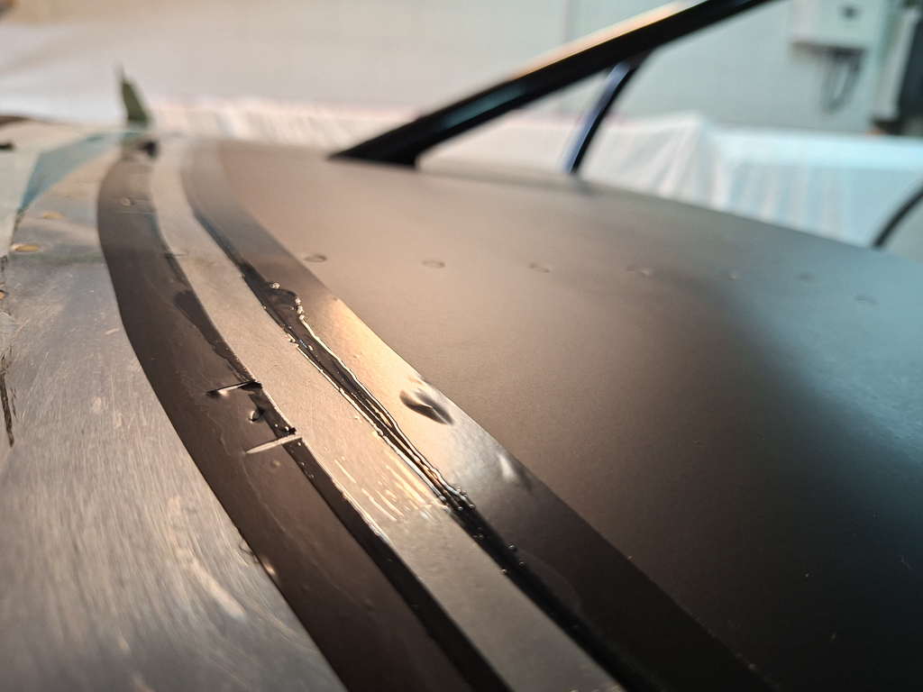
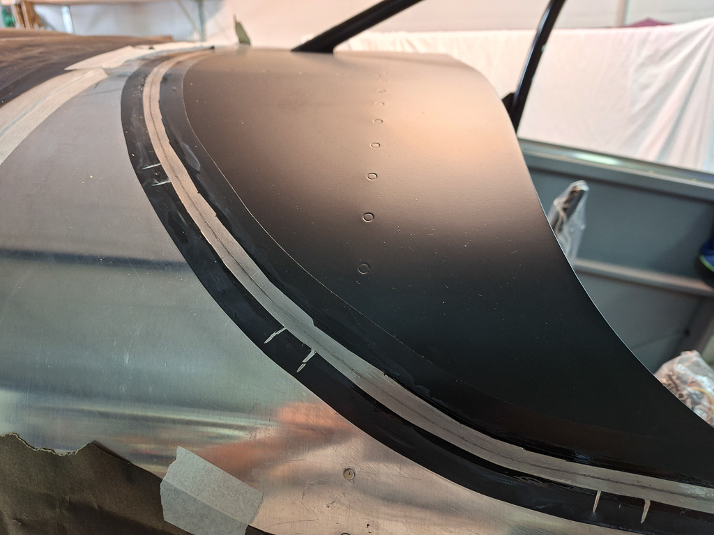
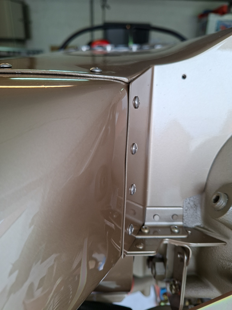
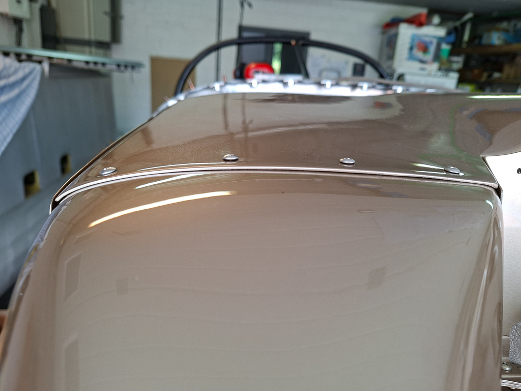
While the top was off , I did some more fine tuning on the paint gap at the firewall on the top cowling. This feels like a never ending story.
It looks quite good and consistent although it's still scary to have this size gap. I do hope the paint indeed closes this up and makes up for a nice butt to butt installation to the top skin.
Next I rivetted the latch on the door. That finalizes the oil door work.
Here is the view from the inside.
It's easier now to explain how the latch works. By pushing the latch, you tilt the locking part upfront up
This is when you release it. You see the locking part moves forward. A spring holds it in place.
In the image below, I had positioned the aluminum lip, drilled it and rivetted it on the top cowl.
To secure the hinge pin, I have installed a small piece of angle with a hole in the center bottom, The pin just fits through. I installed a nutplate above it which holds a #6 screw to hold a little "door" that closes of the opening in the angle. When the door is open, the hinge tilts back and I can use a phillips screw driver to open the "door" and pull out the hinge pin. If ever I need to replace the spring in the hinge, that will be easy to do.
Door closed and operating nicely.
Stupid me did make a small mistake. As I drilled the aluminum strip, I drilled through the door. It took 2 holes before I realised what I was doing. Fortunately this is epoxy and a little dap of the stuff will close them up. Just more work...
Eh voila ! all done and looking very professional
Spent some more time on adjusting paint gaps on the bottom cowl.
There were still some SkyBolts that had the locking pin inside. They only lock when you remove that pin. Problem with these is that it's hard to remove the pin for the skybolts on the pilot side. There is no oil door opening here as on the other side and the cylinders are in the way to reach in from the air intakes.
A simple trick here was to use a piece of epoxy scrap of the same thickness and make a 15/32 hole in it for the SkyBolt stud. Adjust it as you see it in this image with the stud nice and lever with the washer and remove the locking pin. Give it a half twist left or right and it locks in place.
13/08/25 - Test hanging catto prop first time - 1h
A big day again in my project. Nothing substantially done but I have hung the propellor on the engine prop hub for the first time. I kind of wanted an idea how everything would fit together and what is delivered by Catto with the propellor, spinner and saber extention.
I have a 4 inch Saber extention, spool type. This is required for the Sam James cowling installation. It took a couple of tries to find the way to do this but it's pretty self explanatory once you understand things. The spinner is predrilled and cut and the holes in the spinner plate are also made with nutplates installed. This makes it pretty simple.
Short bolts hang the spool to the prop hub behind the starter flywheel. You bolt these in in a star pattern. I am just doing this temporarily so there is no torqueing involved yet. This will come of a zillion of times. The long bolts holding the propellor and everything forward of the spool extentions are very long. The threads also extend quite far through the extension. This is probably for having enough space if an additional weight plate has to be added up front.
Here is a view with the prop bolted on. This is pretty damned cool seeing this a first time.
Milestone day ! This is one of those days that you know mark the timeline of building your airplane. The moment you hang the engine in the engine mount. After many days of thinking about missing any things on the firewall, I came to the conclusion that this is the right moment to hang the engine and move on to the firewall forward work. There are some more things I need to do on the firewall, but it's not possible to be sure about the exact location to drill large holes in the firewall until I can actually evaluate the position with the engine in place. i'm thinking of the mixture and throttle cable and alternate air cable. Other than those, I'm pretty sure everything on the firewall is in place.
The same thinking goes for the rear of the engine case. Make sure the 45° restrictor fitting for the oil pressure is mounted in the engine case prior to hanging the engine. It's almost impossible to install this once the engine is on the engine mount. Mine was already installed by PMM during engine assembly. While you are at it, also install the other oil cooler fittings in the engine case (in and out). These can also be done later but it's easier now.
First step was to remove the safety straps that held the engine to the wood pallet that was used for transport. I want to keep track of how this was done as this engine is a brand new engine that has not yet been on the test bench. When all is ready, I will need to unhook the engine and bring it to PMM Wingservice to have it running on the test bench for a first time. This has the disadvantage of extra work on removing the engine and all connections again and having to do it again after it has been run. On the other hand, the major advantage is that I do not have to worry about corrosion and idle time of the engine as it has not yet been running. The cylinders are as if they would be in a stock location on a bench waiting for an engine. There has been no movement of the cylinder heads on the cylinder walls and everything has an oil film on it as delivered from Superior Air Parts. Whether building takes me another 3 years or just 1, it won't matter. I'm gladly willing to take that extra work knowing there is no pressure.
The engine was protected well on the front and rear crankcase and supported in the front under the front with some wood block supports. I'll have to keep all this in stock so that I can re use it in the same way when I bring the engine back to PMM.
Using the engine hoist, we pulled it up, removed the pallet and moved it over to the front of the airplane. Alain helped me on this task to keep the engine in position. It's best having some extra hands around when you do this as the engine is heavy and the bolts are not always willing to go in as easy as you think it would.
The last part of the moving is the most critical as you don't want your magneto's or fuel pump to bump into the engine mount. Having one person moving and another one guiding the engine is no luxury.
Also notice I leveled the airplane in flight mode. This is much easier to position the engine than if it would be sitting on all tyres which would require you to position the engine at an angle. This leveled way makes it much easier.
I found some documentation online from someone who did this before and described the process. I studied this carefully and upfront, had a close look at the barry mounts and dyna bolt set. You can read it following this link https://www.myrv14.com/buildlog/20150917/Engine_Hanging.pdf. Vans Aircraft also has some drawings available which are not part of the standard plan set that you receive with the kit.
Study the plans carefully, the barry mounts have to be positioned so that the engine rests on the compression side in the bottom and the compression side in the back on the top mounts. The compression barry mounts are the ones that have a step in the rubber. The non compression ones don't have the ribble on it and look like plain rubber. If I remember well, the non compression ones also are a little larger. Also take care that the washers are in the correct locations. The barry mounts come with one big washer in the box. It's good to assemble the order of all this before starting to move the engine and have thing prepared well. I colored the position of the large washer red in the picture above.
There are 2 lengths in the dyna bolt kit. 2 x AN7-43A and 2 x AN7-44A. The longer ones go on the bottom side, the shorter ones go on the top. The difference is not much more than the length of one of the washers.
Start with the 2 top bolts. The first one is very easy... tighten the bolt but don't torque it yet, you'll probably have to loosen them again working on the bottom bolts. You do need to tighten the first so that the barry mounts compress allowing the other hole to come in line with the engine case. Remember this is a dynafocal mount, the bolts point inwards. If the bolt is not tightened enough on one side, it's impossible to insert the second one. As you tighten the bolts, the barry mounts compress and also position themselves in the engine mount. That's important.
What I found very annoying is that you can't put a socket on the bolt head as the engine mount is in the way. I used an extension on the wrench but that didn't make it easier.
The engine sometimes needs a bit of persuasion to get it in position :) Although I don't think this did much. Found out later it's more important to tigthen the other side and use the engine hoist to lower or lift the engine a bit in order to get a bolt in.
The large washer goes between the compression mount and the crankcase as a spacer for the bottom mounts. On the top mounts, I have put that washer on the compression mounts under the bolt head as you can see in the image below. The image has both top bolts in place and tightened.
From there on, things went less smooth and it took about an hour or 2 before I got the last bolt in so I did not take any more pictures until it was done.
I'll try to describe the further process I took.
As both top bolts were tightened, I lifted the engine a bit using the engine hoist. This allowed me to slip the barry mounts between the case and the engine mount. Don't forget the large washer between the barry cookie and the engine case. Don't forget the compression side of the barry mounts is against the engine for the bottom mounts. Then I lowered the engine again and after some wiggling I was able to put the 3rd bolt in. I did have to loosen the top bolts a bit though.
The fourth bolt is the most difficult one. Looking with a mirror through the hole there was no way the bolt would go in. After a lot of moving up and down, I finally discovered my problem : the washer between the barry mount and the engine case was not aligned and the pressure on it is high enough that it makes it hard to move it. After lifting the engine a bit and tapping on it, I could get it more or less into place. A second trick I used was to take an old bolt which was smaller in size and grind down into a guide pin. Once I could slide that smaller bolt in, I was able to wiggle it around in order to get that washer and the engine hole into alignment. I put some grease on the final bolt shank and finally was able to put it in with only very light tapping of a rubber hammer.
I was feeling relieved as I bolted the final nut on that fourth bolt.
As final step, I torqued the bolts. These are AN7 which take 450 - 500 inch/lbs. I used the middle value of 480 inch/lbs. The engine will still need to come off as mentioned earlier but the position of the engine is very important when installing the cowling so I torqued it to the final value.
Took some pictures of the plane with the engine in place. This surely is a big milestone and is a "feel good" moment during the build.
Happy camper...
As I had some time left, I took out the fuel throttle body. This comes with a plastic spacer.
The orientation of the throttle body was a bit of a mystery at first but soon figured out what side was the throttle lever and which side the mixture. In the image below I installed it on the forward horizontal induction air intake at the cold sump of the engine. In the image below, the throttle lever is the gold colored arm.
Finally I covered the intake with some paper and masking tape in order not to get foreign objects entering the engine.
End of a productive day was off course celebrated with Alain with a good strong Belgian HQ beer.
Some advice on reading my log for fellow builders !
In some articles, I made corrections at later date on the original article to rectify my own stupidities or faults. Read through the entire article if you intend to use my findings/experiences on your own project !
At the Oshkosh airventure 2013, I took this cool shot with Richard VanGrunsven, founder and CEO of Van's aircraft. We had a short chat after he came out of a presentation where he attended putting the young eagles project in the spotlights.
Richard -usually known as "Dick" or "Van" was born in 1939 and became an American aircraft designer and kitplane manufacturer. These days his kits are so popular that the number of VanGrunsven-designed homebuilt aircraft produced each year in North America exceeds the combined production of all commercial general aviation companies.
Oshkosh is to you like Mekka is for a Muslim. If you haven't been there at least once in your life, you will NOT go to aviation heaven !
From Belgium, it's quite a trip but in the last five years of building, we managed to go twice to Oshkosh.
Nothing beats the experience of Oshkosh air venture in Oshkosh Wisconsin.
The first time we went, I visted sun'n fun in spring and decided to also visit Oshkosh. On sun'n fun there were rv's but the experimental parking there is kind of isolated and more difficult to make contact. So my idea before arriving in Oshkosh was, 'wel I hope there will be some RV's'.