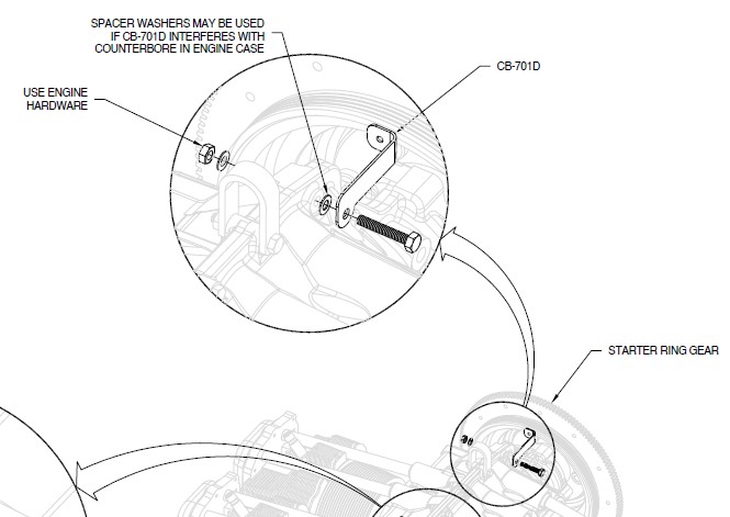
After making modifications to the rear bracket, it's time to tackle the forward bracket. The image below is the original bracket as provided by Vans in the baffle kit.
You cannot use that bracket and you should create 2 new custom brackets that support the front baffles. The location of the hole in the engine is the same but the bracket looks different.
This is the location on the engine where the brackets will come. They support the left and right side front baffle.
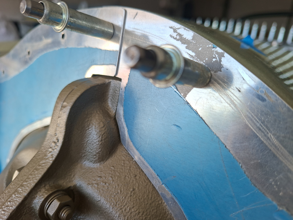
these are the front baffles from the Bill lane plenum, so not to be confused for builders who have the standard Vans baffles.
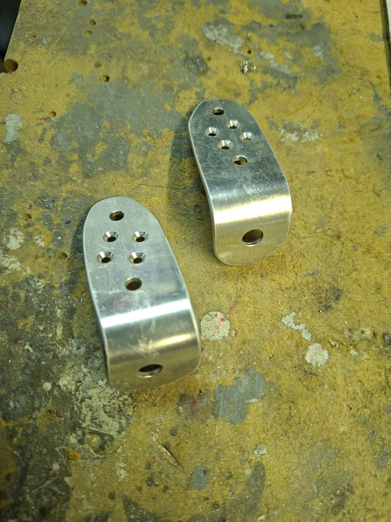
First I started cutting some 0.063" alu stock sheet and made the bend. The bend needs to have a large radius here. There is a serious amount of stress caused by the engine vibration and sharp bends are a garantee for cracks down the road.
Using a simple small bending brake and home equipment it's not as straightforward to create a bending that has a certain radius.
I found a good way to do this in an easy way. I took a socket wrench which has an outer radius close to the bending radius I wanted and squeezed that on the aluminum while bending. It create this nice radius on the aluminum bracket.
I have deliberatly left the ears on both sides to long so I could start filing away material from the short ear so that the bracket butts nicely on the front baffle and mates nicely with the bolt location on the engine.
I gradually reduced the length and then made sure I rounded down the lower part. There is not a lot of space there so go gentle to keep sufficient material after drilling the #12 hole for the bolt.
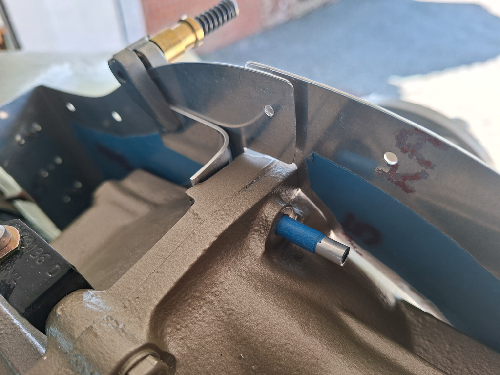
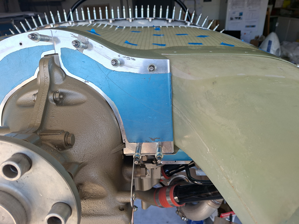
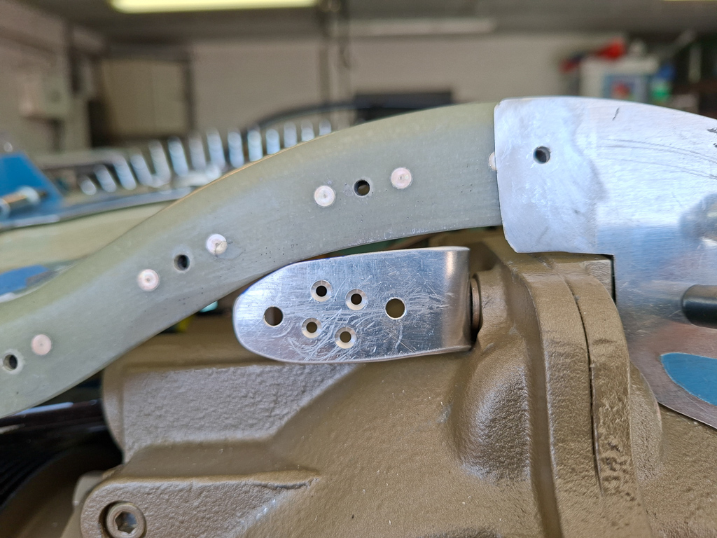
Then Clamped the bracket in place with cleco clamps. You can see in the image what I ment above with filing and rounding down the length and bottom rounded corner.
Once I was happy with the alignment, I used a #12 bushing and put it through the engine bolt hole and drilled a #40 hole in the bracket.
I would recommend using a bushing. it's a scary idea havig to put a twist drill through an engine case hole and drill away.
The bushing gives me a perfect centered hole which I enlarged off the engine on the workbench to #12.
In the image above you can see the bushing I used was a piece of aluminum tube which was a little undersize and I just wrapped some painters tape around it which placed it snug in the engine bolt hole.
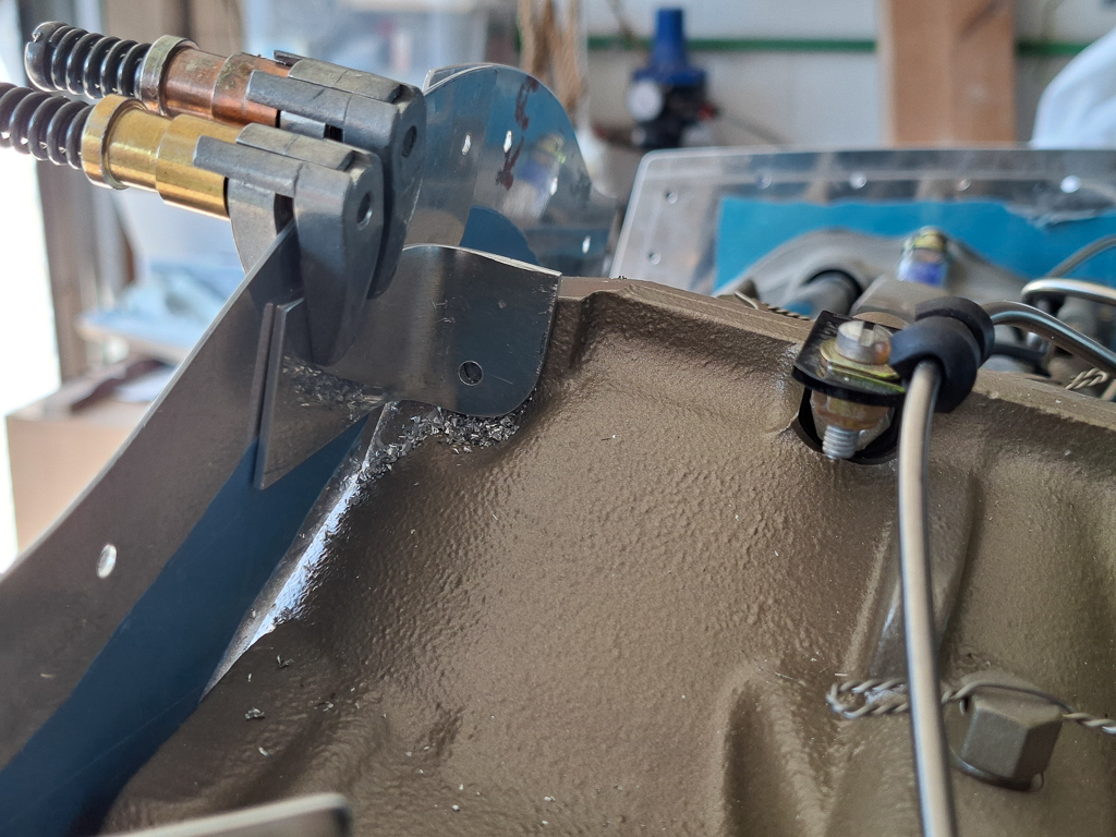
Then drilled the pilot holes #40 for the #8 screws in the front arm of the bracket. This requires some planning as you will need to be able to mount 2 K2000-08 one ear nutplates diagonally on the bracket.
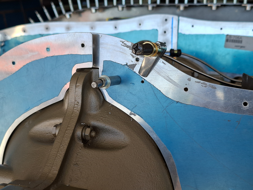
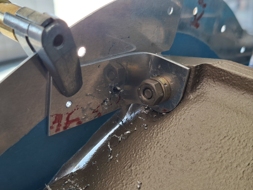
Then updrilled the holes for #8 screws, and temporarily screwed the nutplates on so I could use the nutplates as templates for drilling the ear rivets.
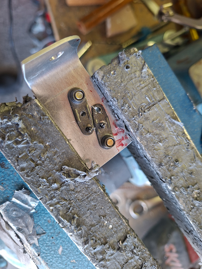
It looks like this with the #8 screws in place
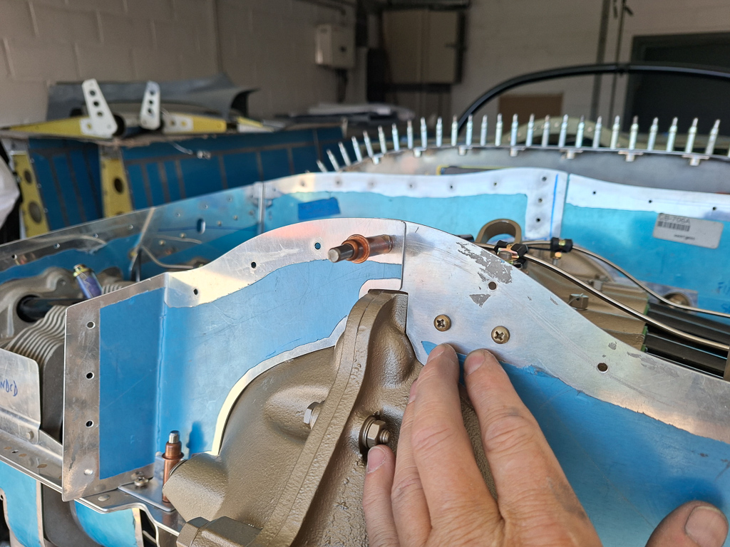
Then drilled then pasenger side the same way.
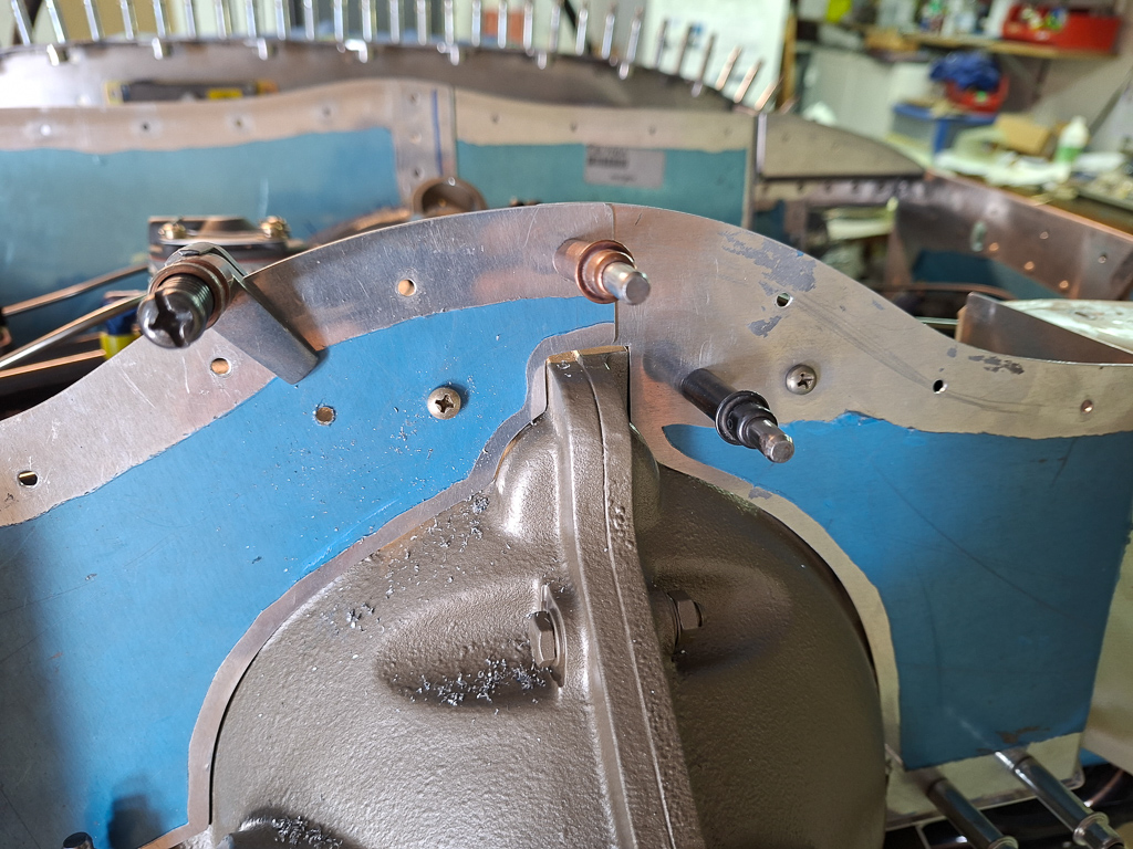
Behind the scenes look. The bolt in the engine case has become to short to accomodate the extra thickness of the 2 brackets. There will be an additionalwasher between the engine case and the bracket as well. I have ordered a longer bolt at spruce: SUPERIOR MS90725-13 BOLT (Part# 08-10875 MFR Model# MS90725-13).
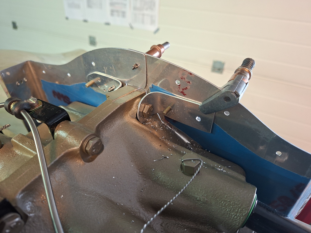
The drilled the remaining nutplate ears, deburred the holes, countersunk the ear holes and cleaned the edges.
I test mounted the plenum cover and discovered som interference with the vertical flange of the plenum roof.
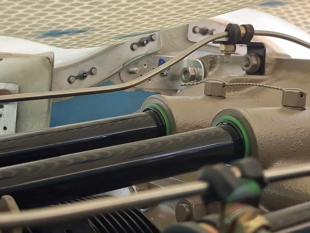
I marked the interference on the flange and will file it clear of the bracket. No issue with strength, there is an aluminum doubler behind the flange.
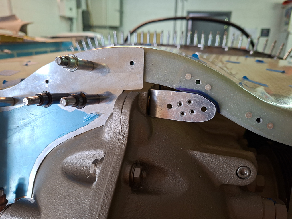
After some tweaking this is how it looked like, the other side has less interference and only needed minimal adjustments
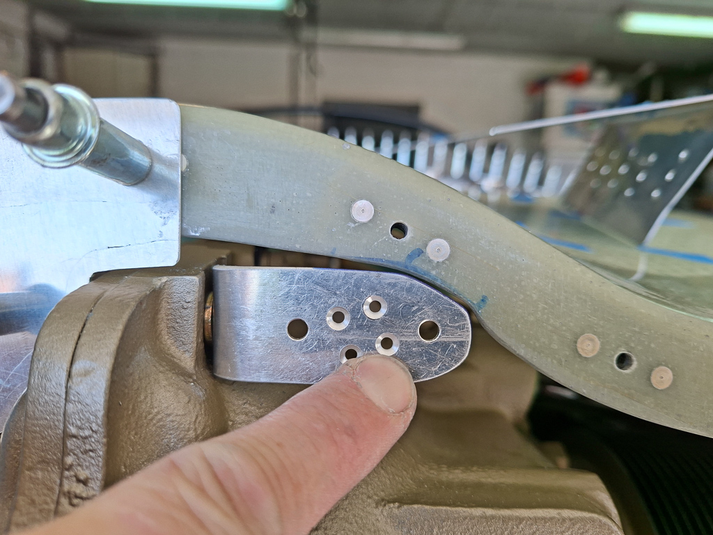
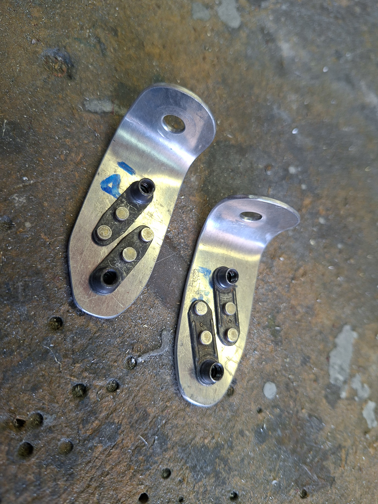
Nut plates installed, these are ready for painting and final installation.
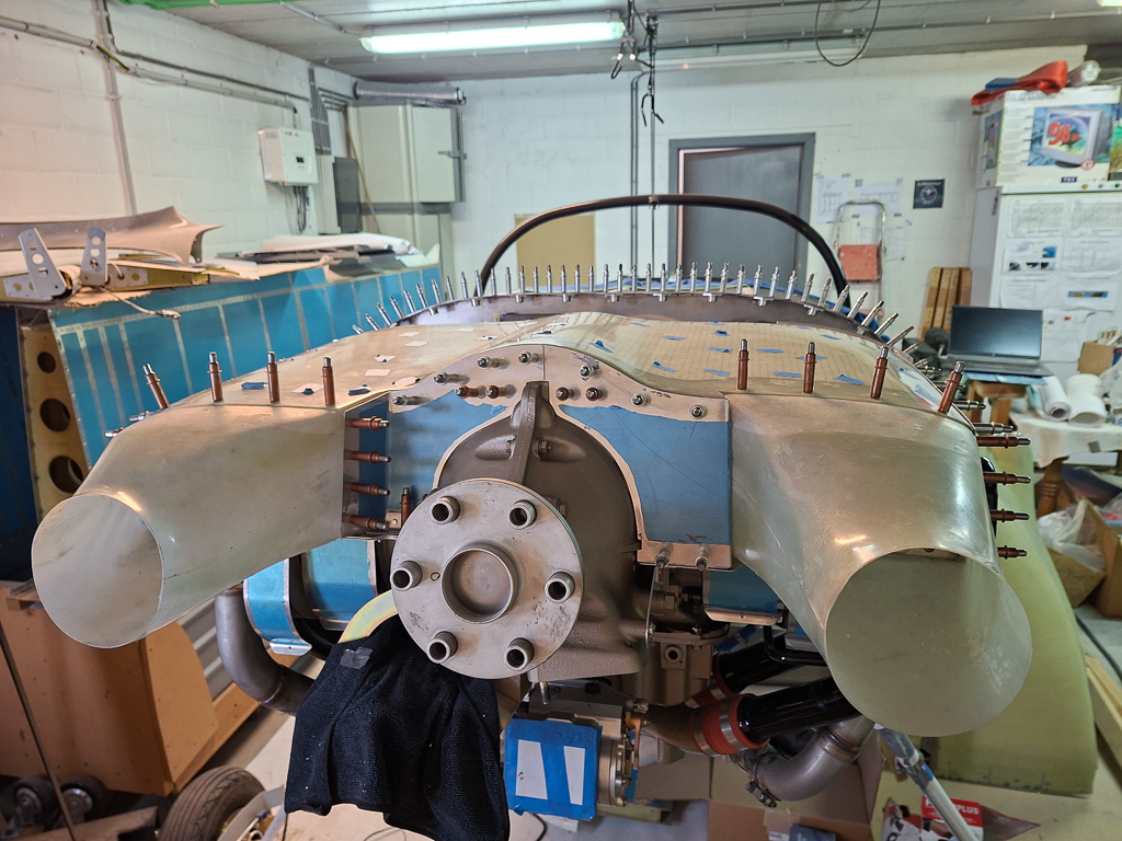
Ended the day with the traditional assembly picture, this time with the front baffle brackets installed.