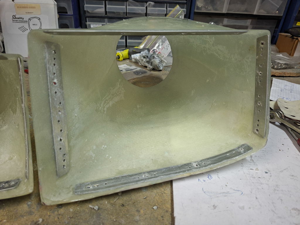
The standard Vans baffle kit comes with a support bracket that attaches the rear baffles to the engine using 2 top engine case bolts via the CB-707D bracket.
The Bill Lane plenum ends up lower than the Vans system that uses rubber sealings near the top of the cowling.
Bill Lane plenum has a half inch spacing between the plenum top and the cowling top. Things are already more thight with the Sam James cowl compared to the Vans cowling and this lowered plenum leads to a situation where the support bracket is too high. I have to modify this angle and come up with a modified version.
I have cut off the top of the support angle and will use the remainder.
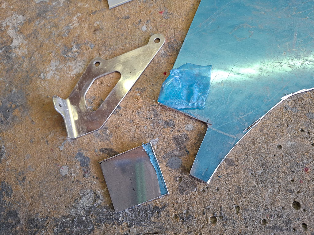
After cuting of the top, I also cut off the flange. This will be replaced by a customised angle out of 0.063" stock angle.
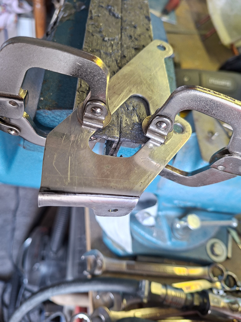
The image below shows the angle attached to the bracket underneath the plenum cover. The difficulty in this is to position the angle on the bracket and have a nice butting connection to the rear baffle.
As this is far underneath the cover, there is no way to hold this or change it while the lid is on.You'll have to remove the plenum top, adjust the clamps and try again until it lays flat on the rear baffle.
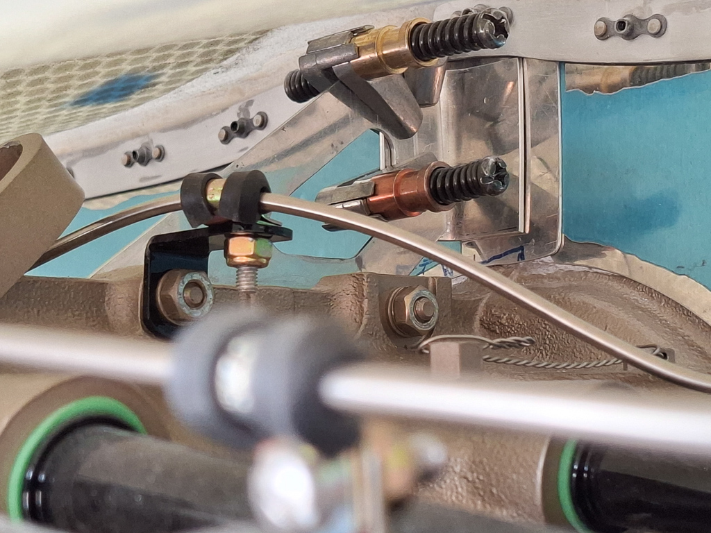
After a couple of iterations I got it right and drilled a couple of #40 holes through the support angle on the engine. This fixates the position of the rear angle.
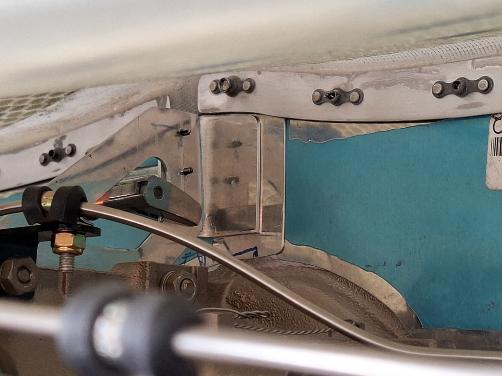
There are 2 # 12 holes already in the rear baffle. The top one is the one that has the nutplate on the plenum cover above the support bracket. I replaced this #8 nutplate by a AN3 nutplate and will install a bolt through that hole in the plenum top.
Then I reused the lower #12 to matchdrill the angle and drilled an additional #12 hole between the 2. Temporarily fixated it with bolts and castle nuts.
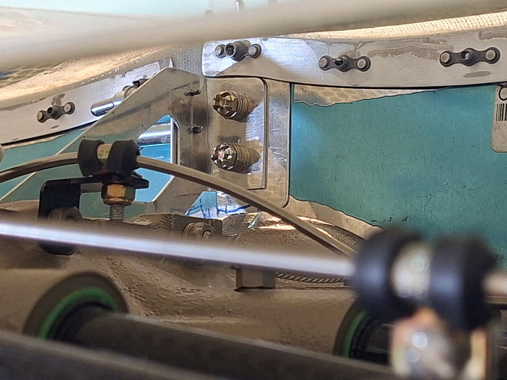
Here is the result before rivetting after rounding down the corners of the support bracket angle.
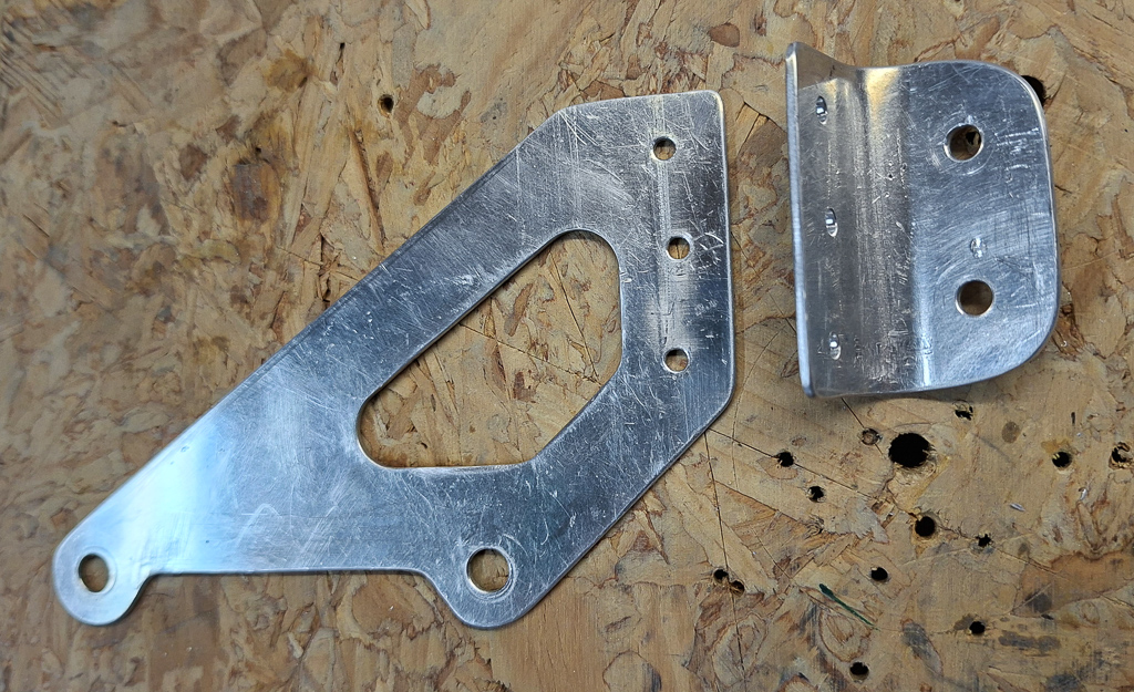
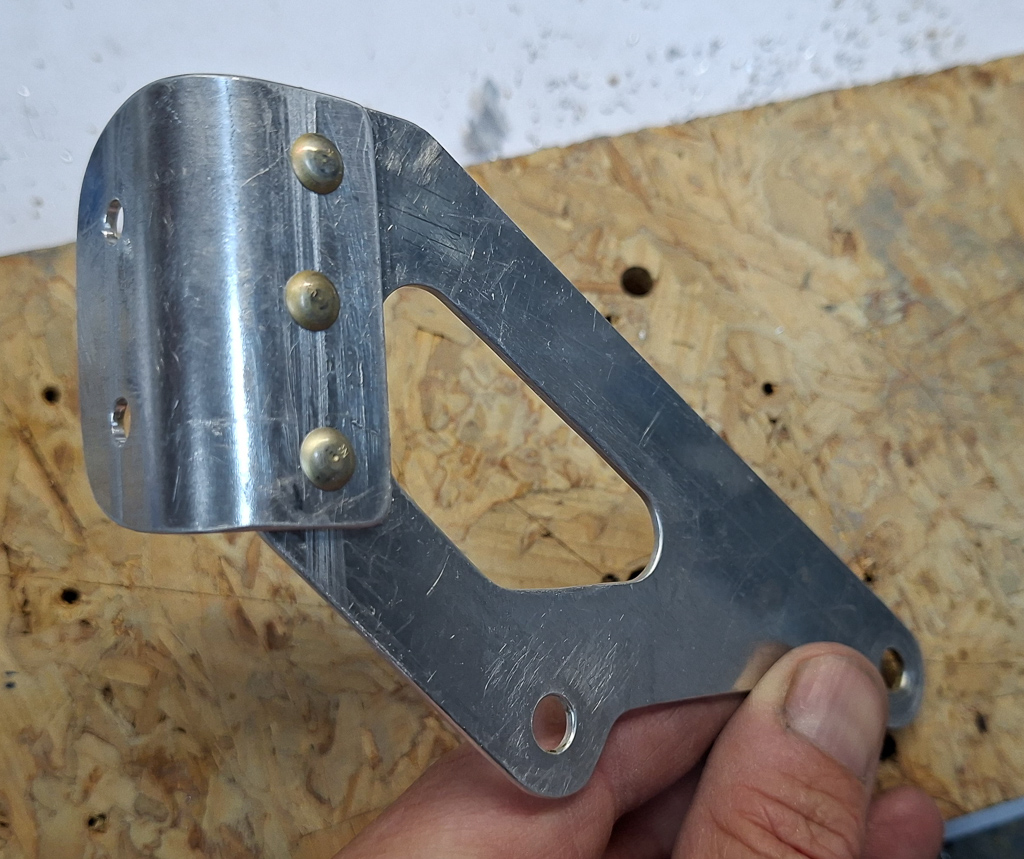
Used some AN470AD4 rivets to attach the angle to the bracket.
Next I made some more aluminum doublers to strengthen the nutplate connections of the diffusers. I glued them in place with some west system epoxy and 406 colloidal sillica to thicken the epoxy.
As before, I'll have to ream the holes again after glueing as the epoxy closes the holes in the epoxy again. The method I use is first use a deburring tool to free the contours of the existing holes in the aluminum strip and then use a reamer to open it up again as it was without enlarging the holes.