Some more small tasks on the firewall forward installation.
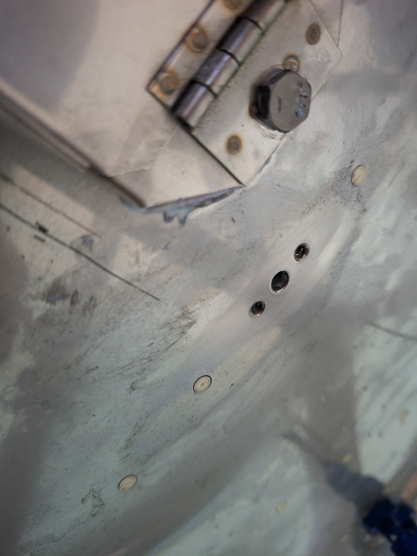
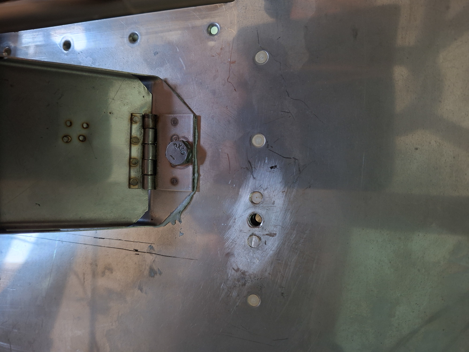
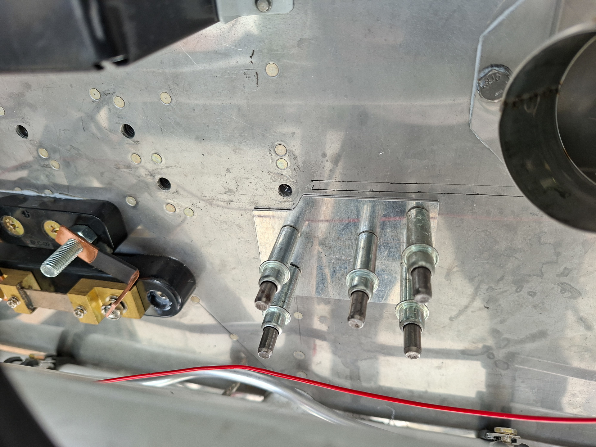
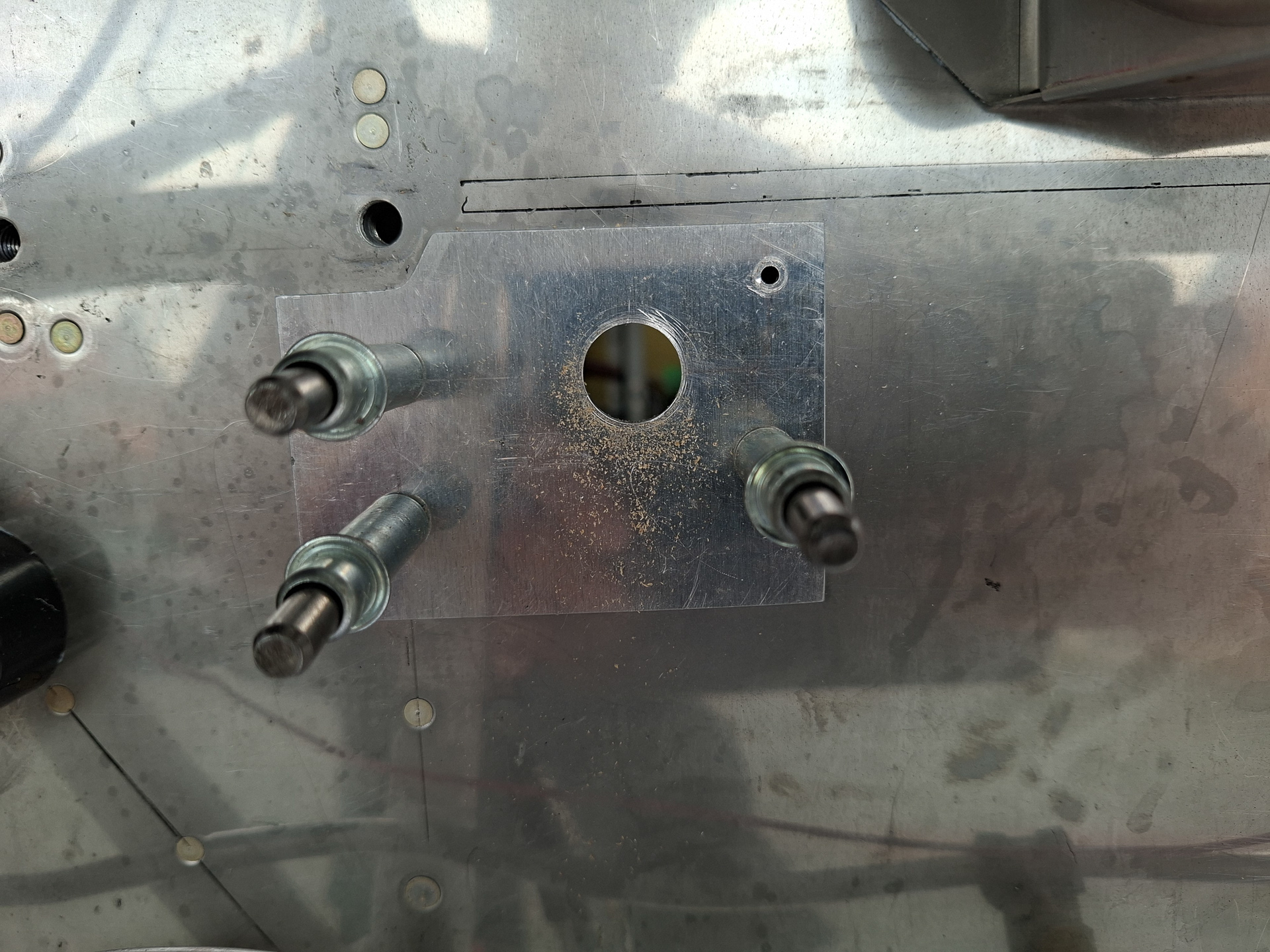
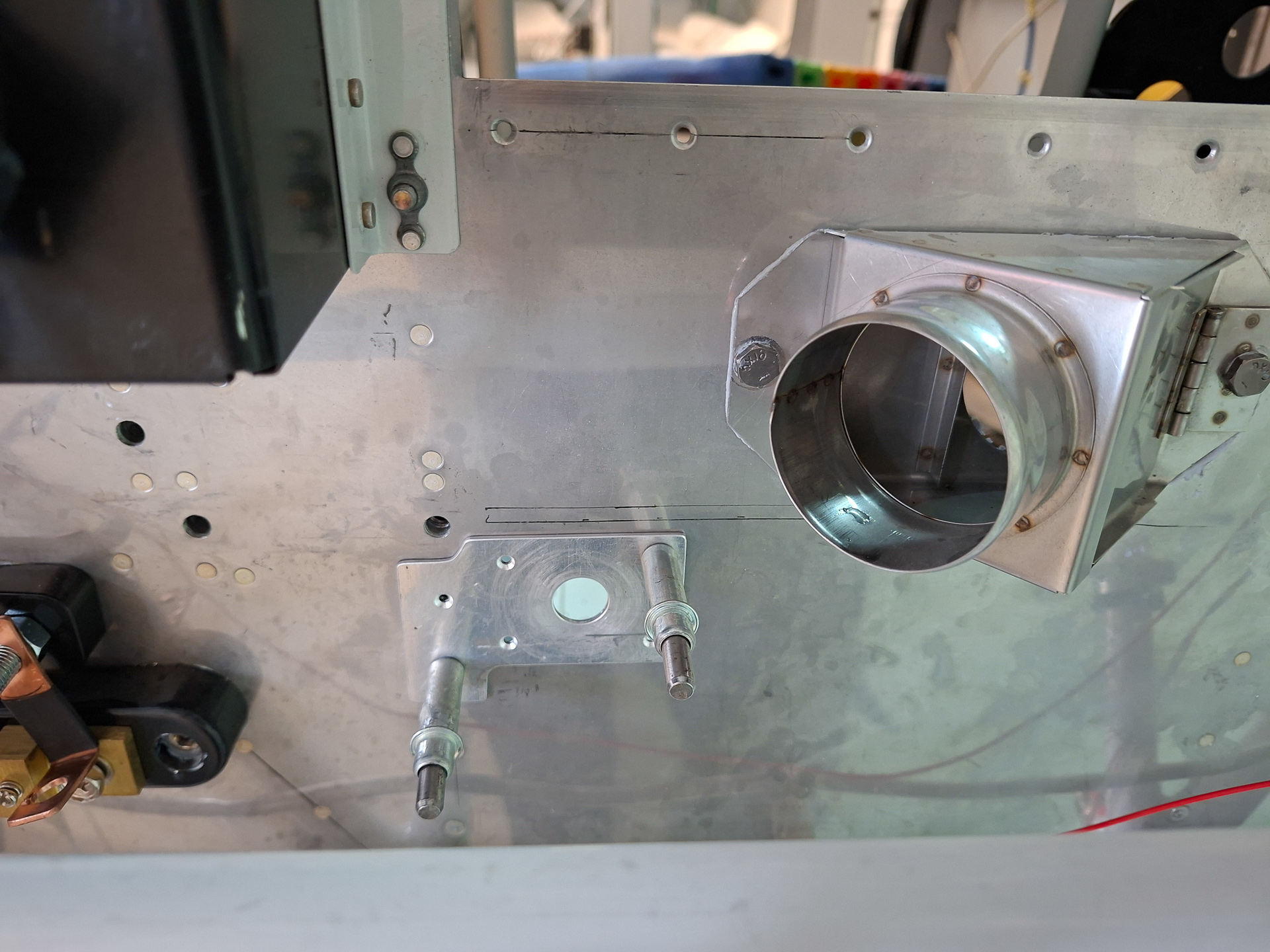
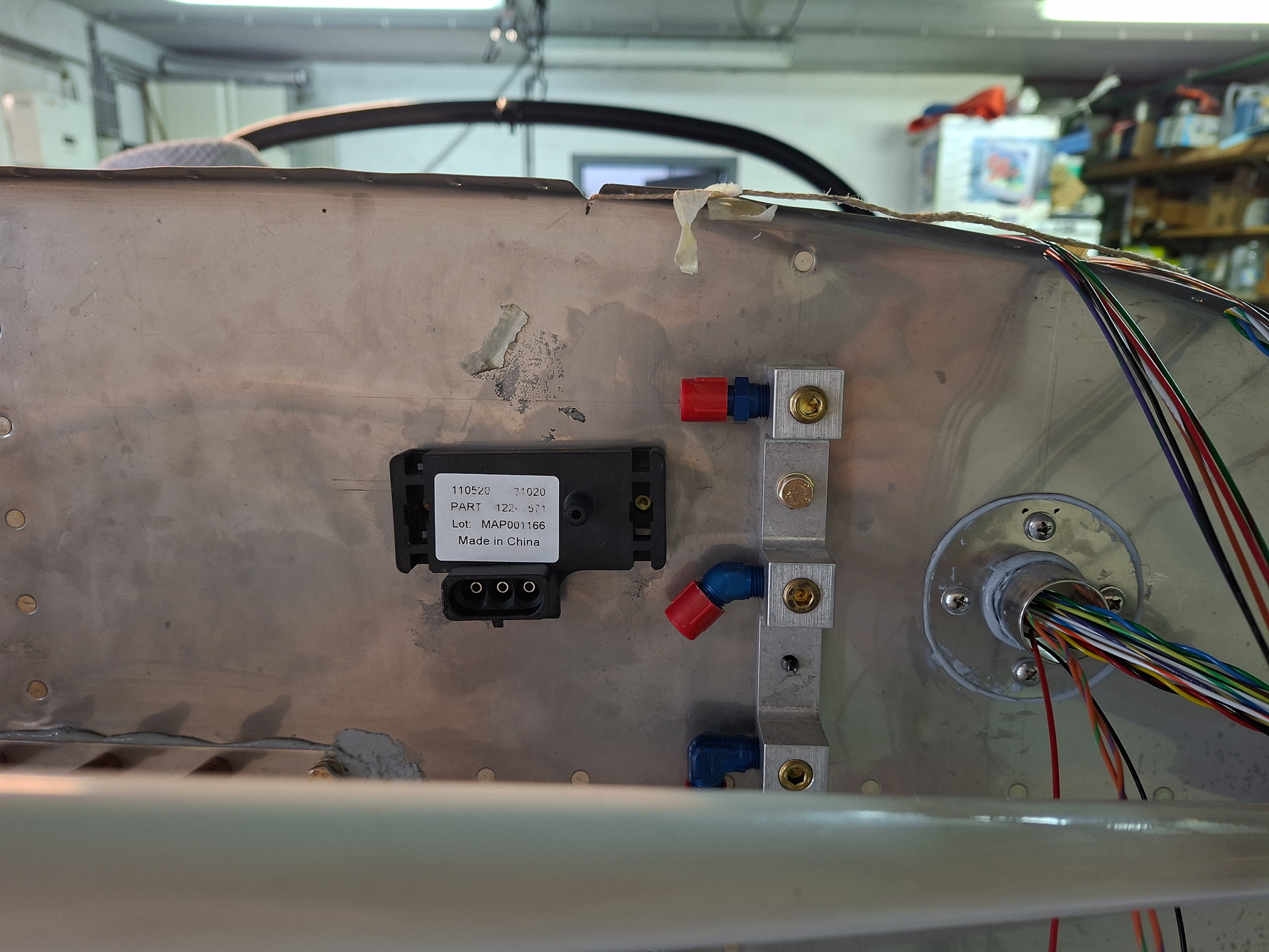
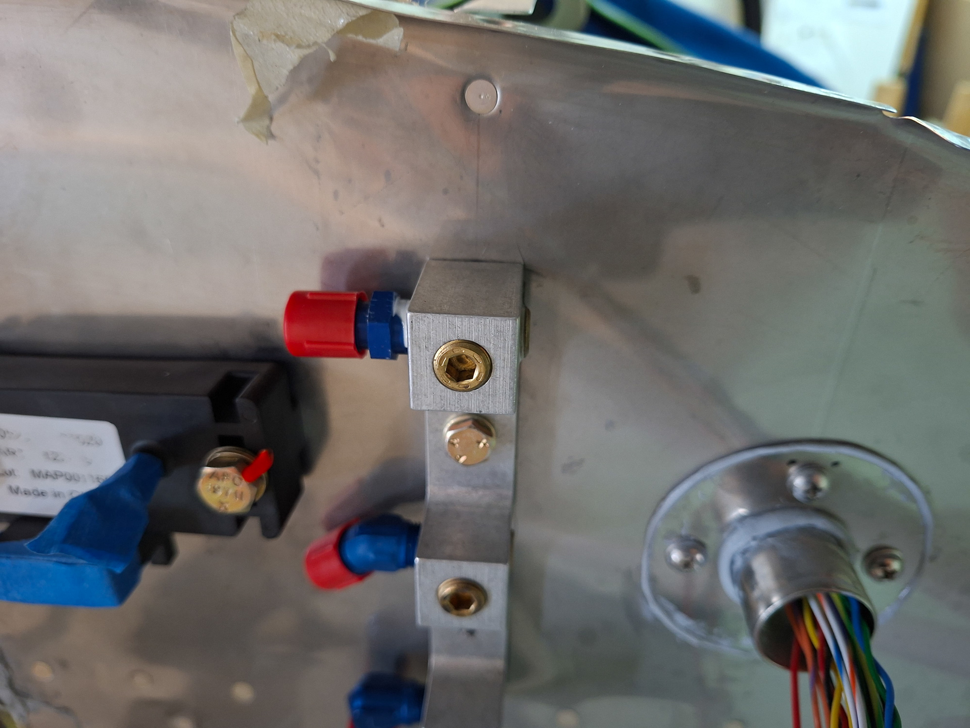
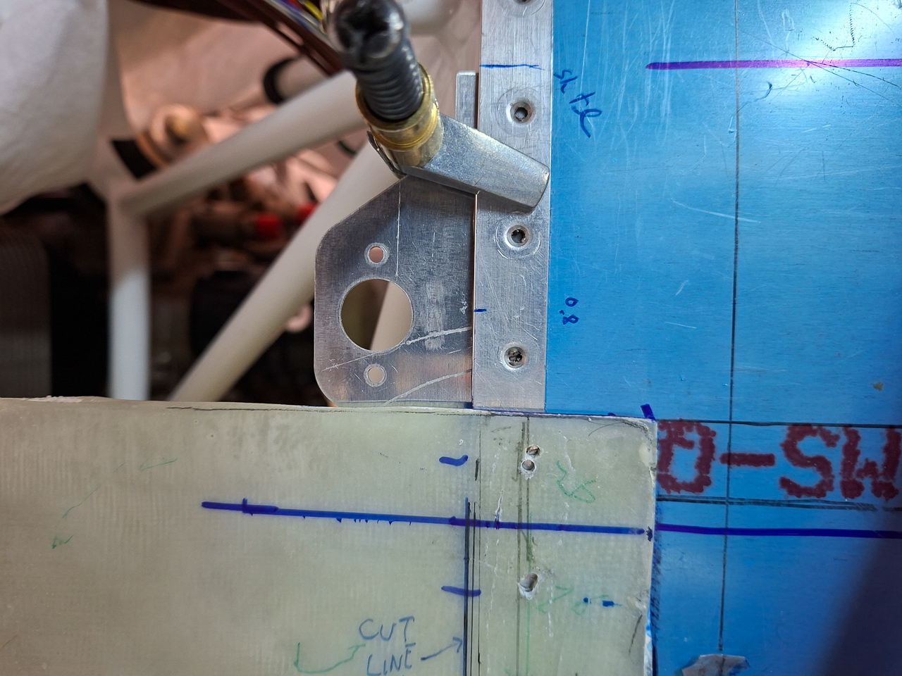
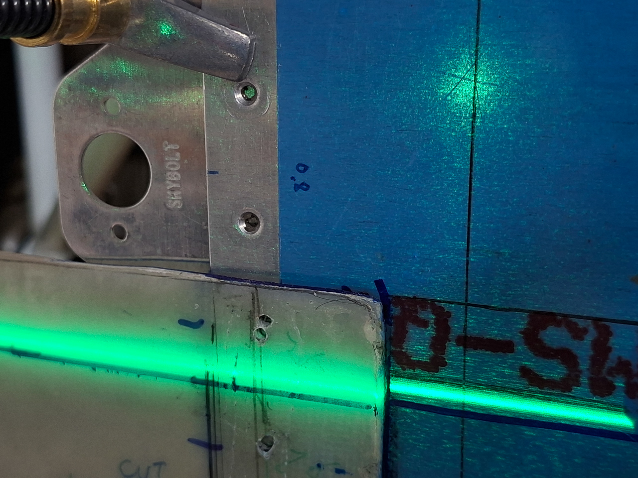
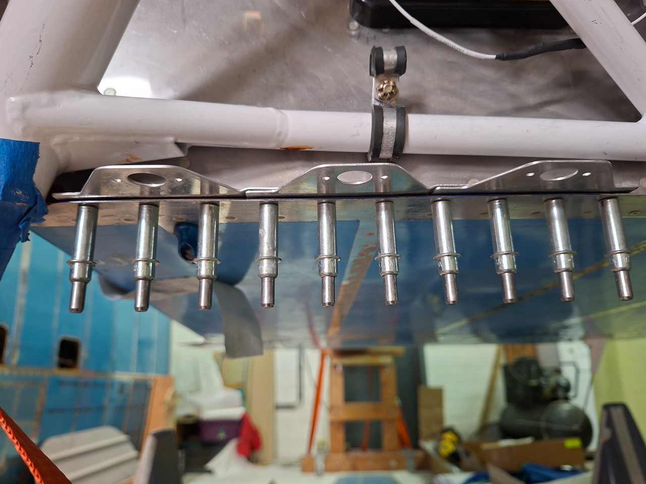
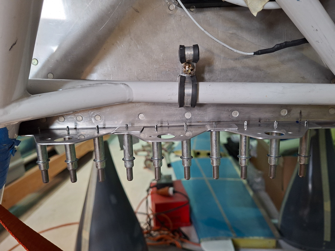
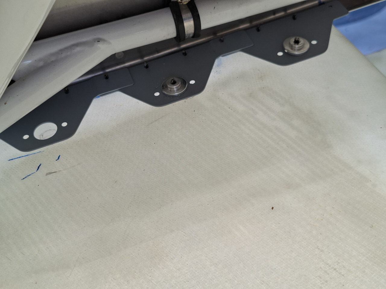
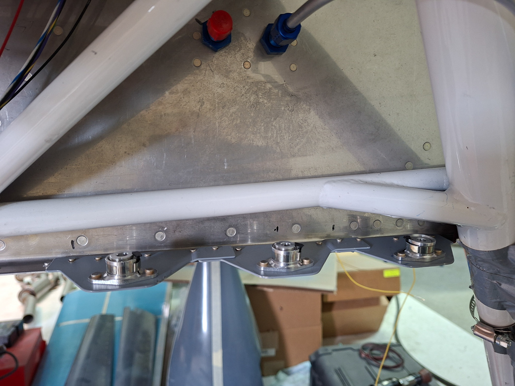
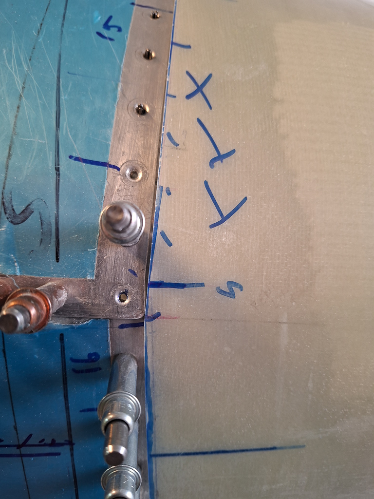
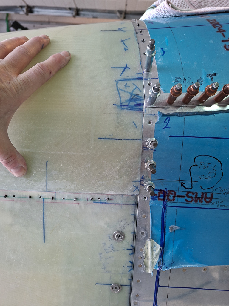
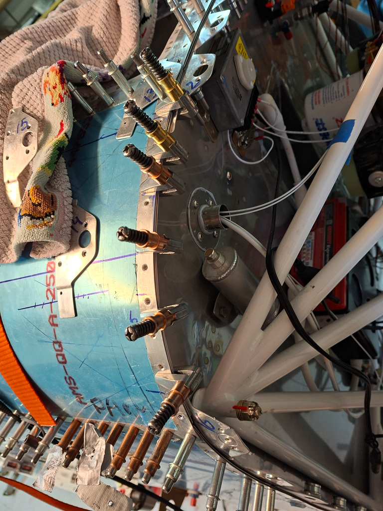
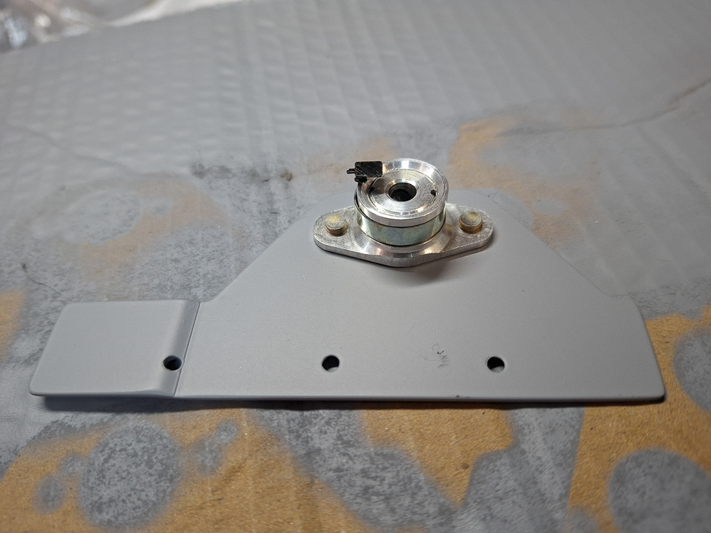
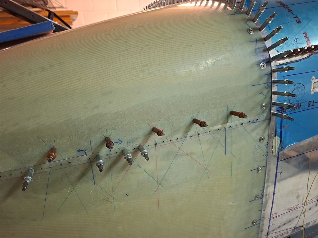
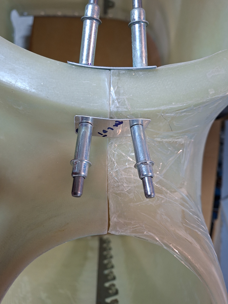
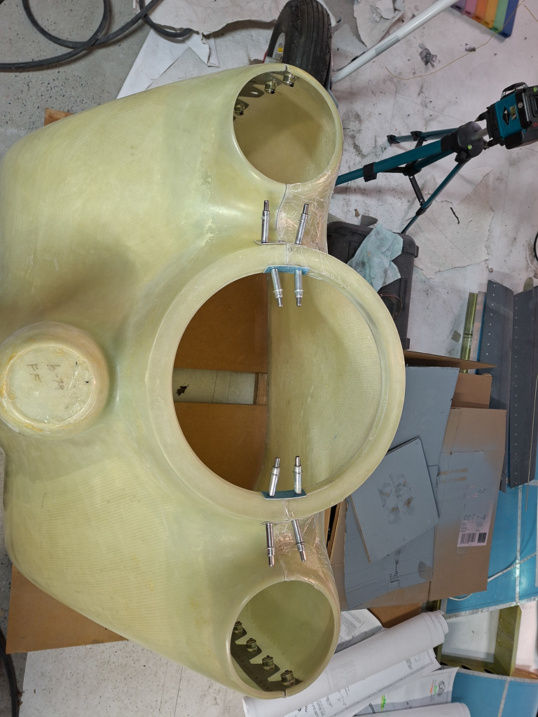
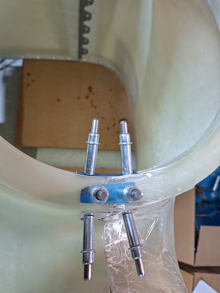
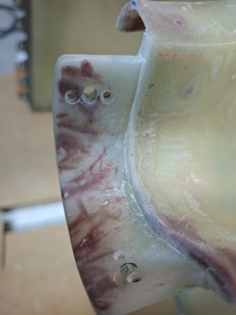
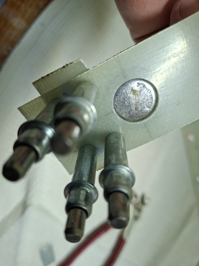
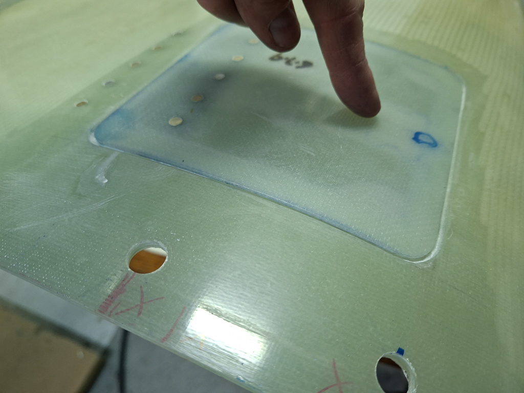
Located the position for the transducer manifold. This is the small aluminum block that allows to plug lines and sensors. It's used to measure fuel pressure, oil pressure and manifold pressure and is located on the opposite side of the pilot side rib using and enlarging the existing holes.
I also started surfing a bit for a good location for the firewall penetration of the sensor wires and other electrics and came up with this image found on another builders website.
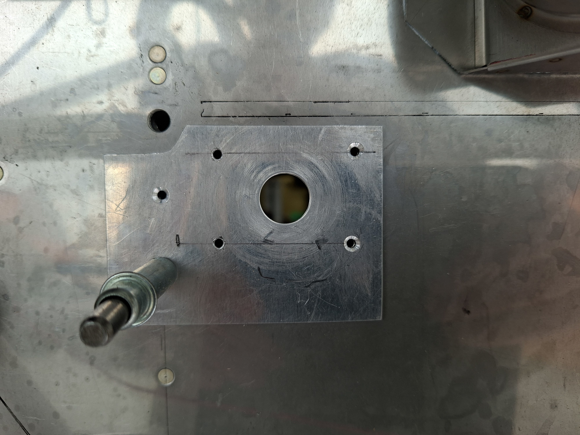
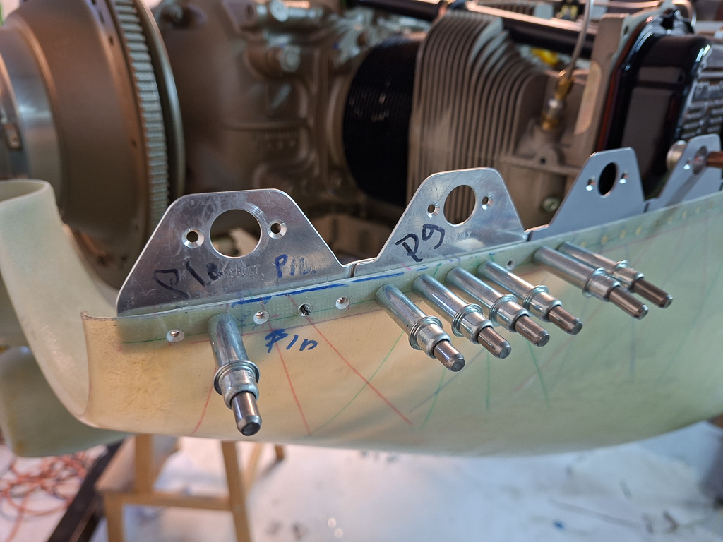
Enlarged the first hole #12 which is in common use with the F-7108-L rib. This is the center hole on the rib and the top hole in the transducer. Then centered the transducer and drilled the other holes for AN3-5A Bolts as per the plans (VA-168 installation on OP-32).
15-12-2021 - Solenoids and diodes
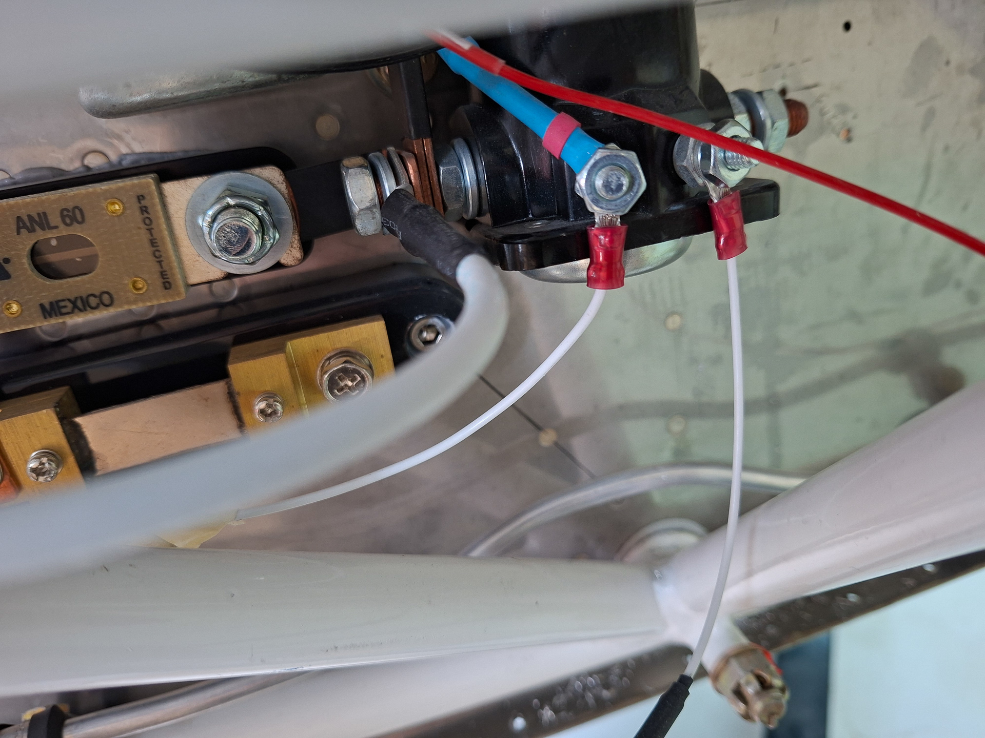
Had some fun installing the starter and master solenoid to the firewall.
Made a copper bar connection between the common posts and shrinked some shrink tube over it to insulate.
Also installed the 2 diodes which had been hanging around in the shop for a while. They are better of on the plan than losing them somewhere in the hardware stock.
18/03/2023 - Firewall Passthrough - 3h30
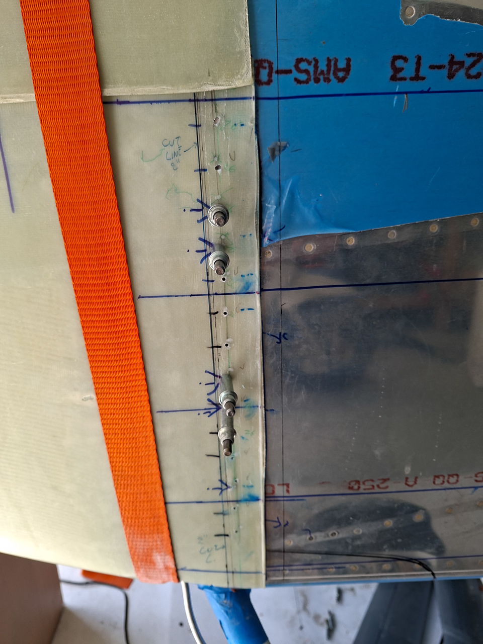
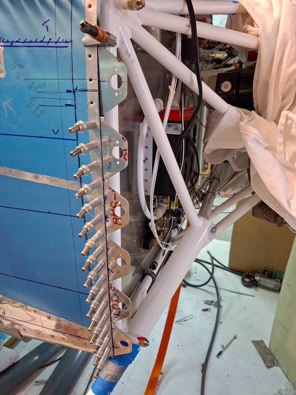
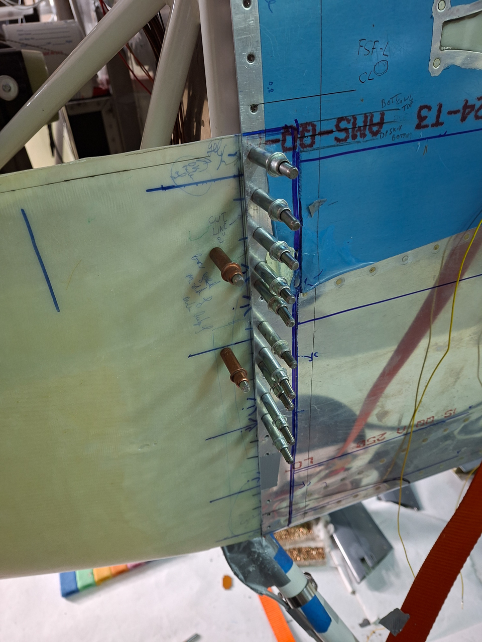
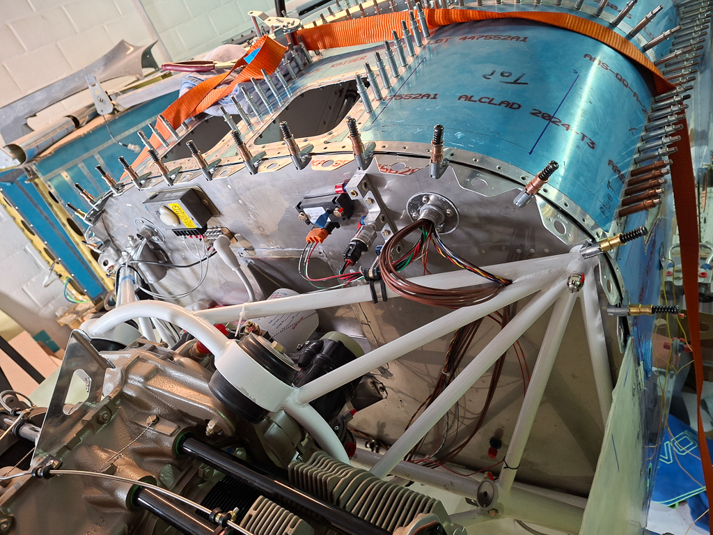
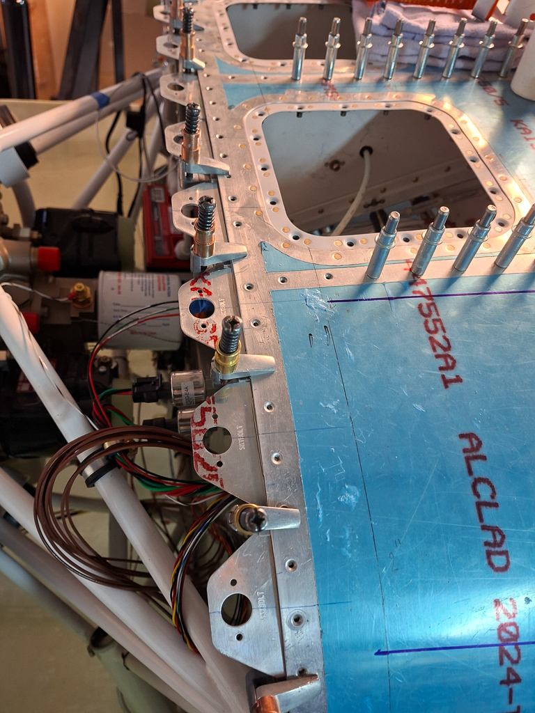
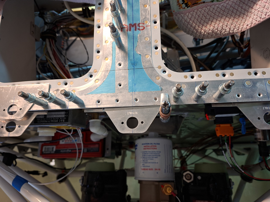
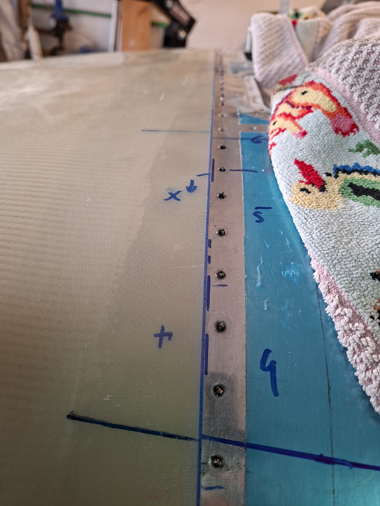
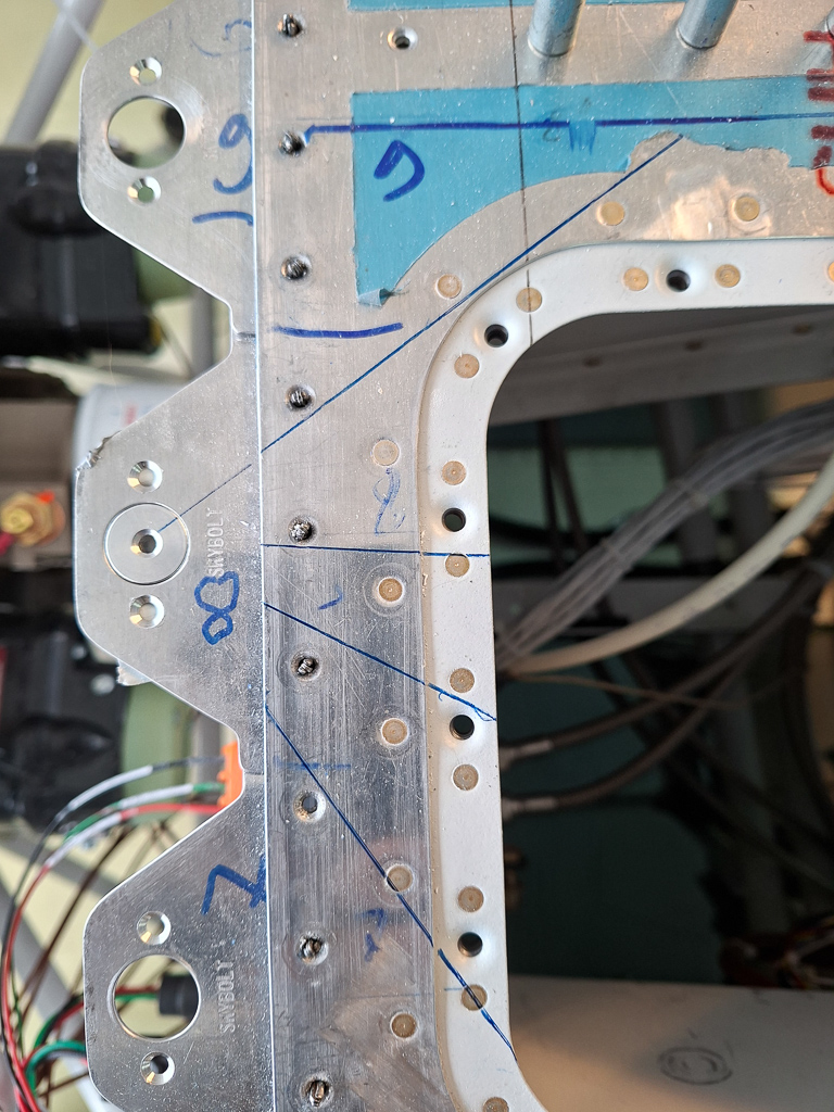
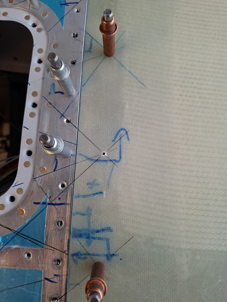
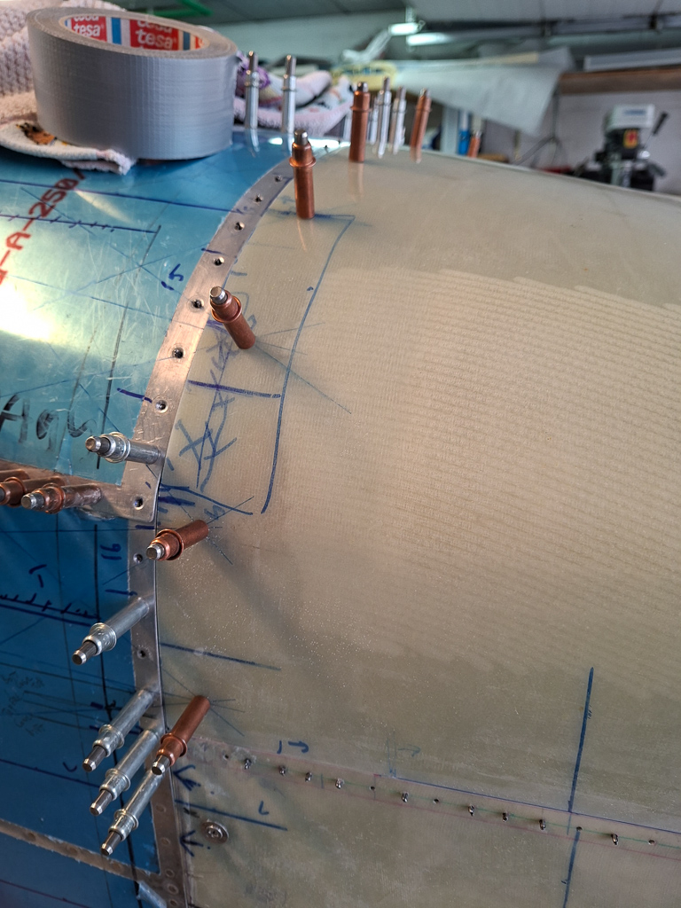
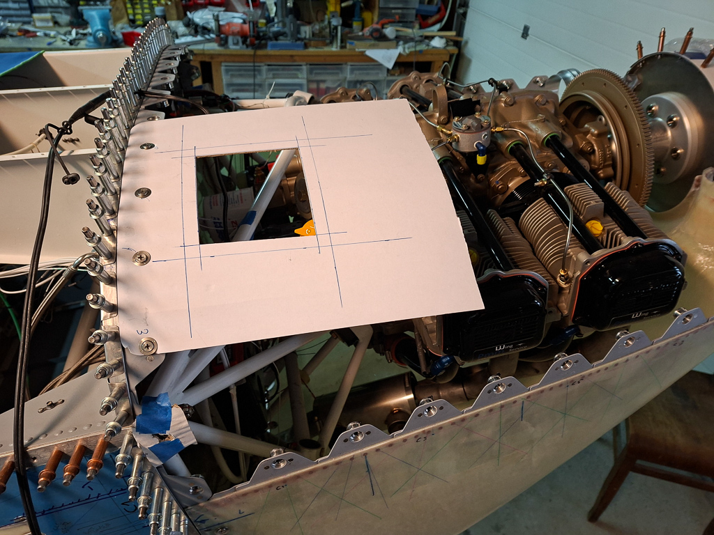
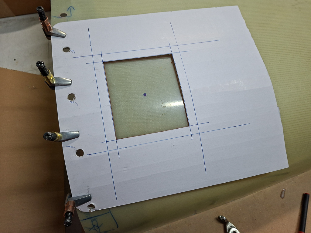
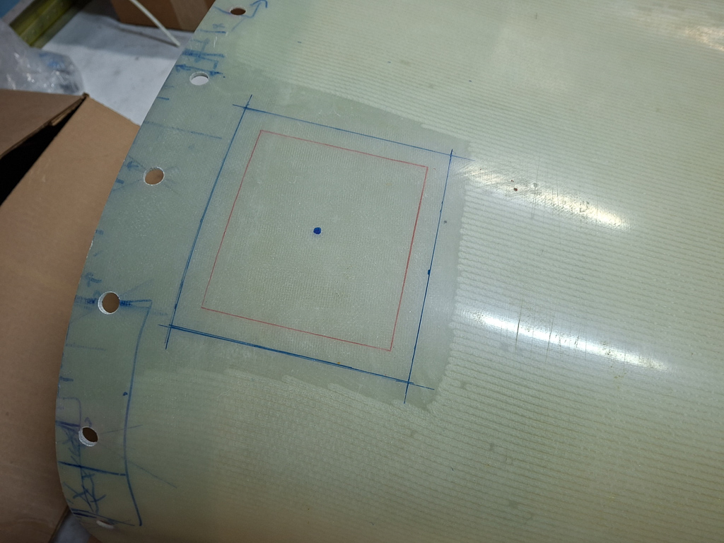
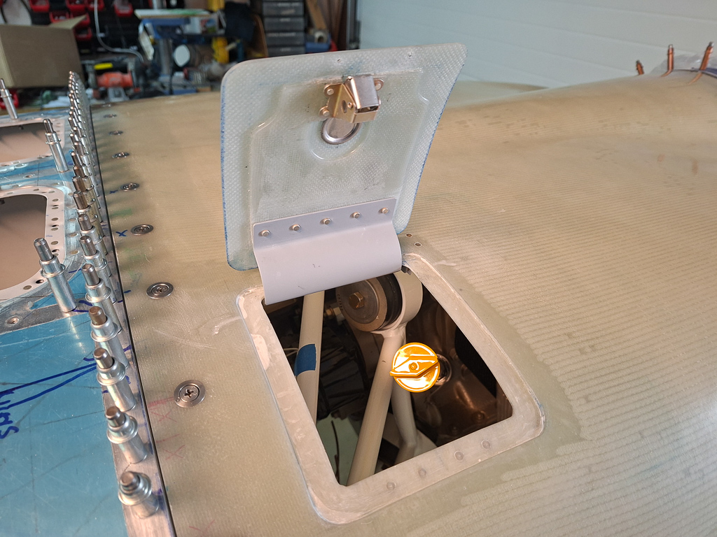
In final preparation before hanging the engine mount, I had to think of the remaininng firewall forward plate work. One of the things missing were the firewall passthrough holes for electrical wiring on both left and right side. The left/passenger side hole will be used to pass the battery cable to the vpx and master switch etc. The right side will host engine monitoring cabling.
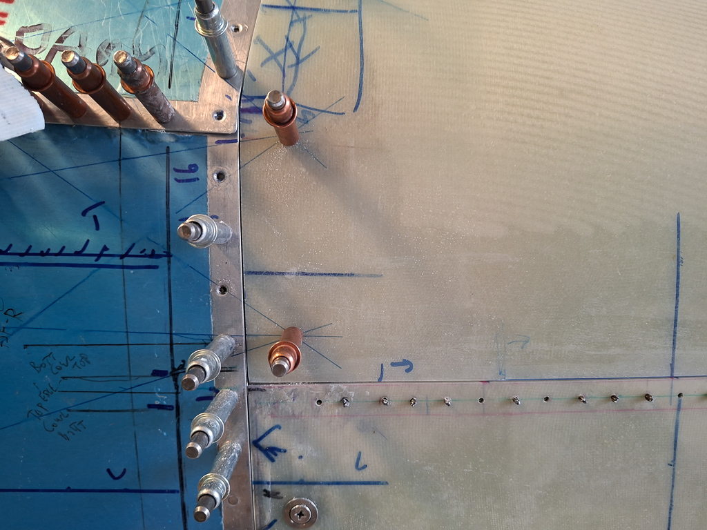
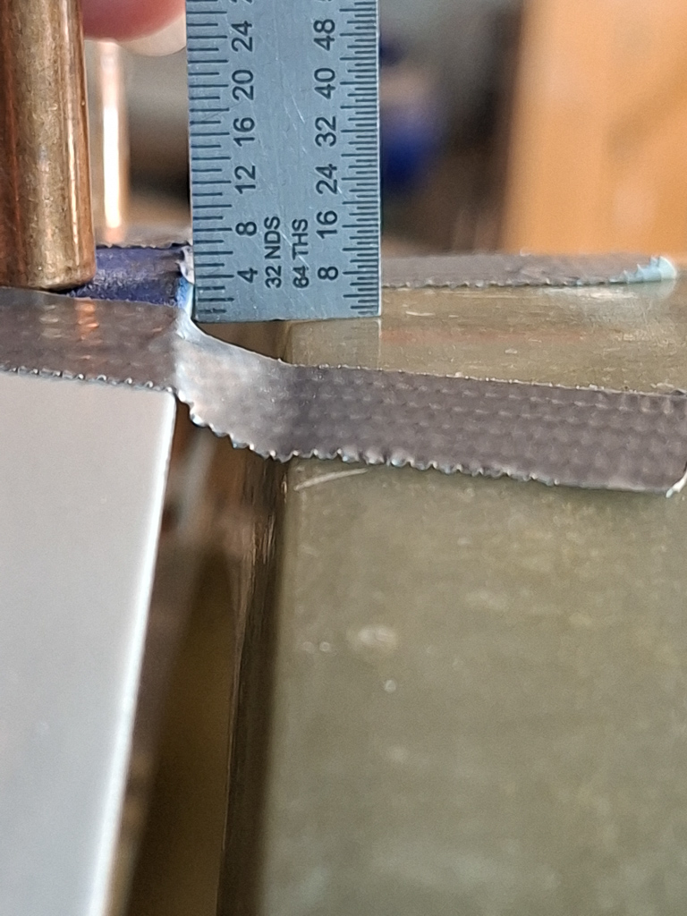
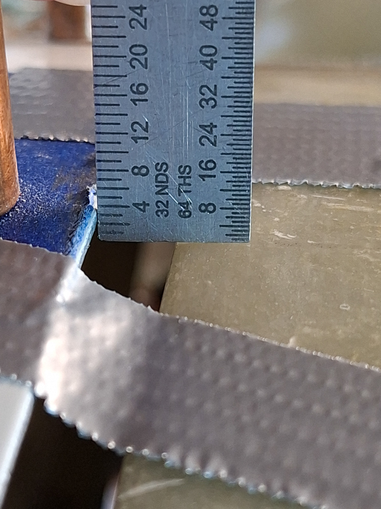
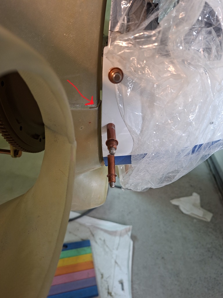
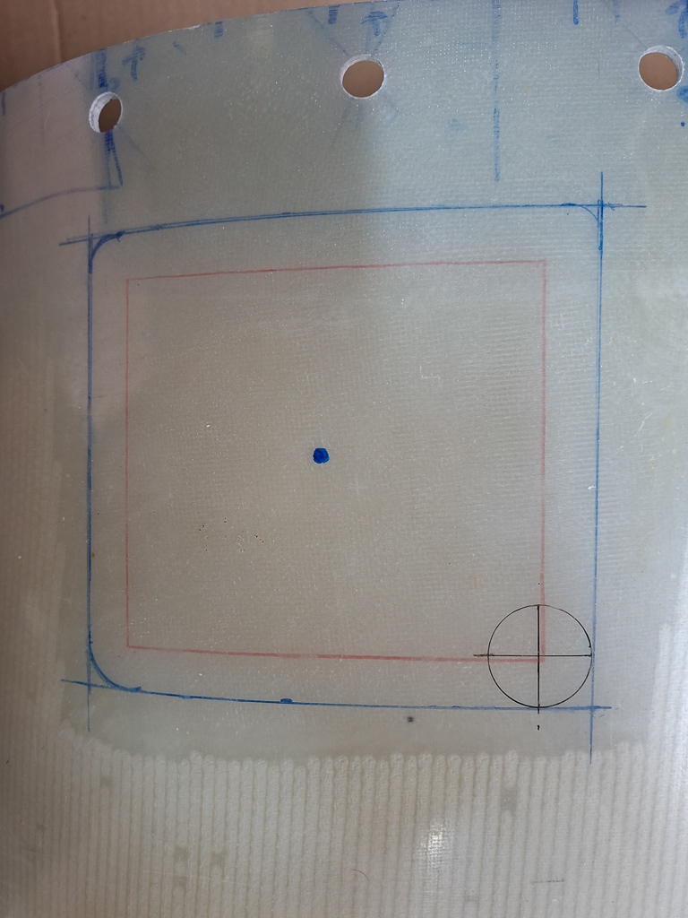
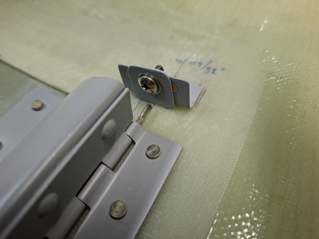
There are no location specifications on the plans but found the dimensions as shown in the picture from Bruce's website. 2 inch from the top angle and 2" 9/16 from the top rib. I did the same on both sides.
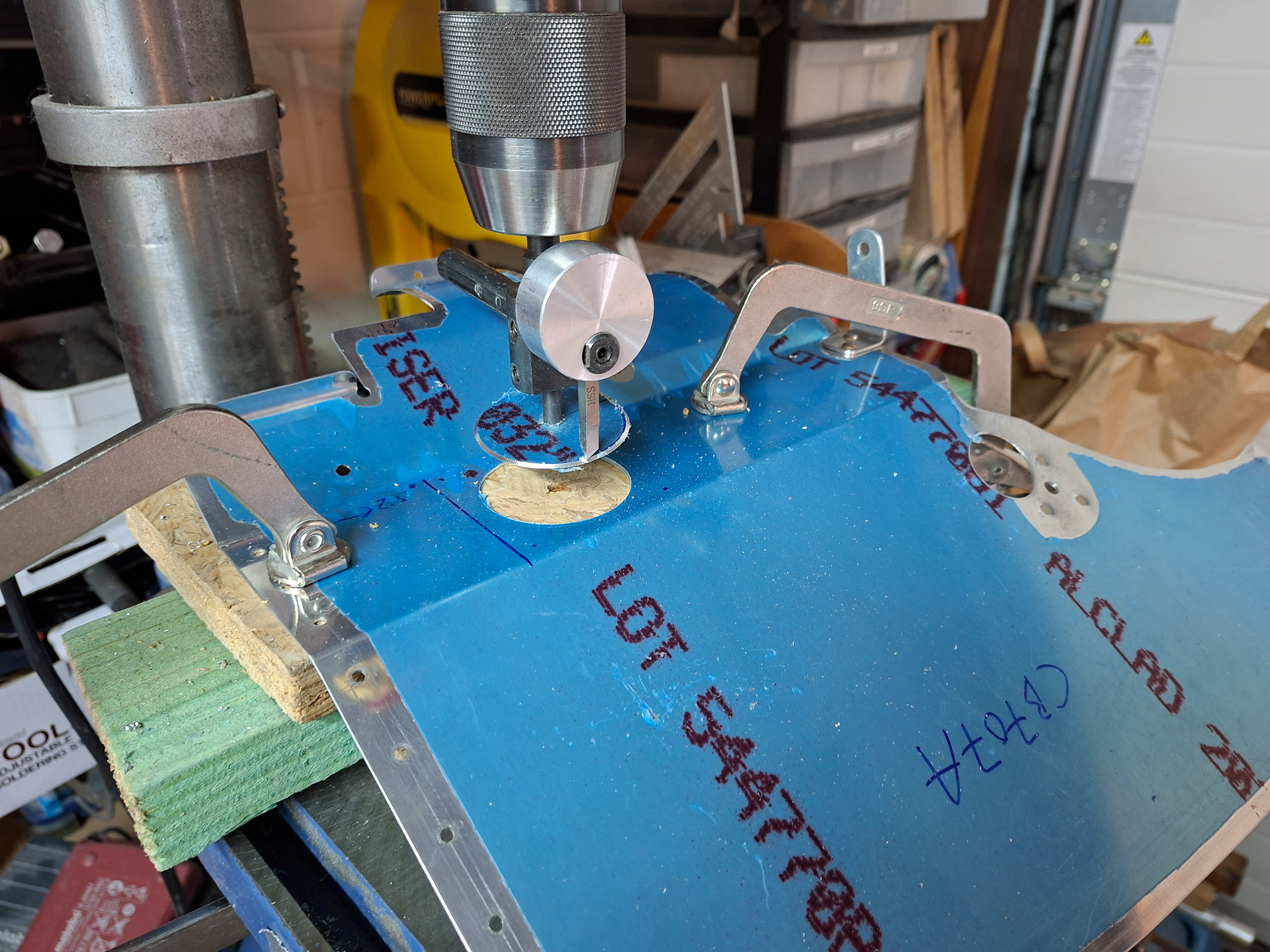
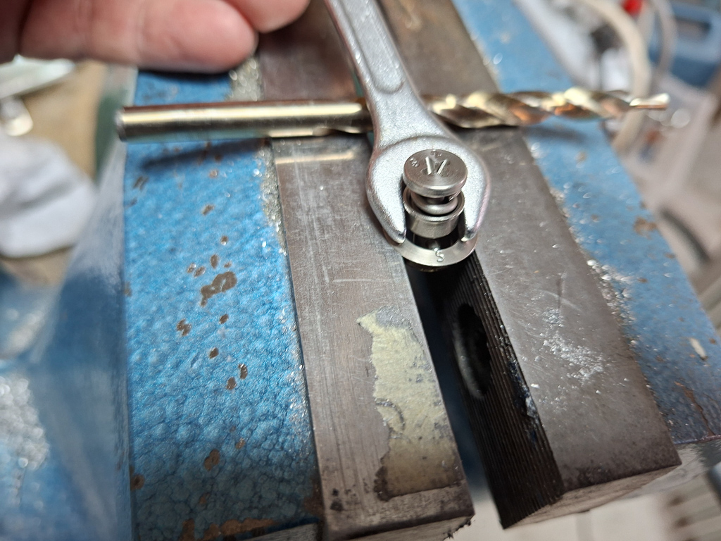
Drilling through stainless steel firewall is a pain. The firewall plate is mounded so no way to use a drill press. I figured the best way would be to have the back supported by a clamped big wood block.
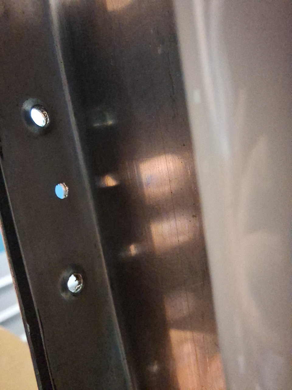
Made the first cut on the pilot side with a regular twisted drill bit #40 and then enlarged.
Used a hole cutter to upsize to the larger diameter and deburred carefully. That stailess steel burr will cut through your finger like a knife goes through warm butter.
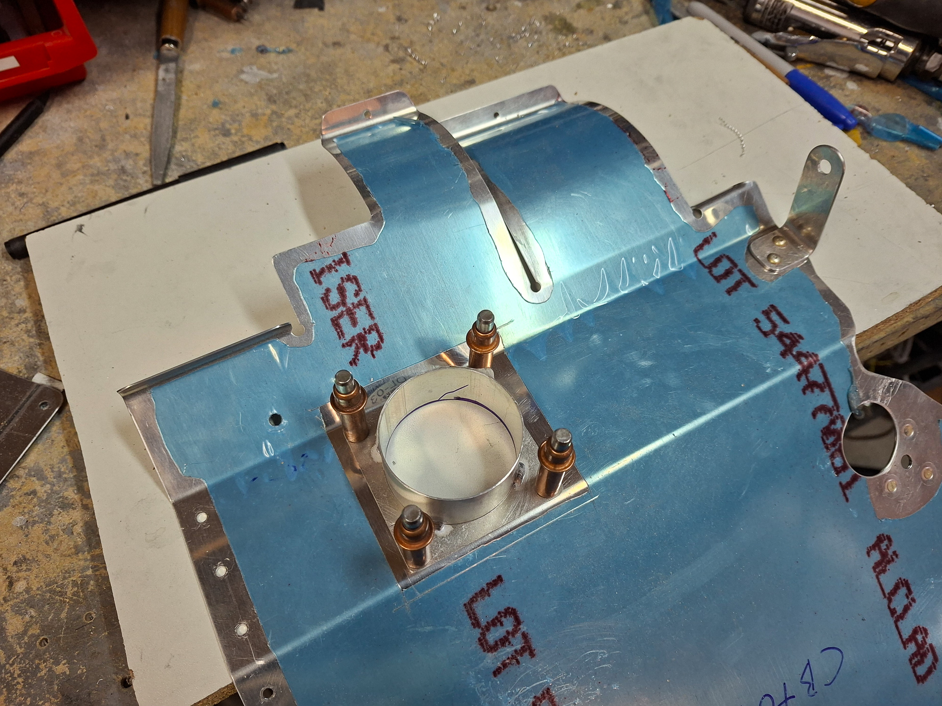
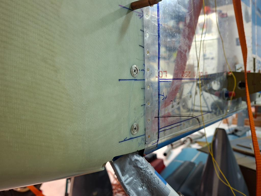
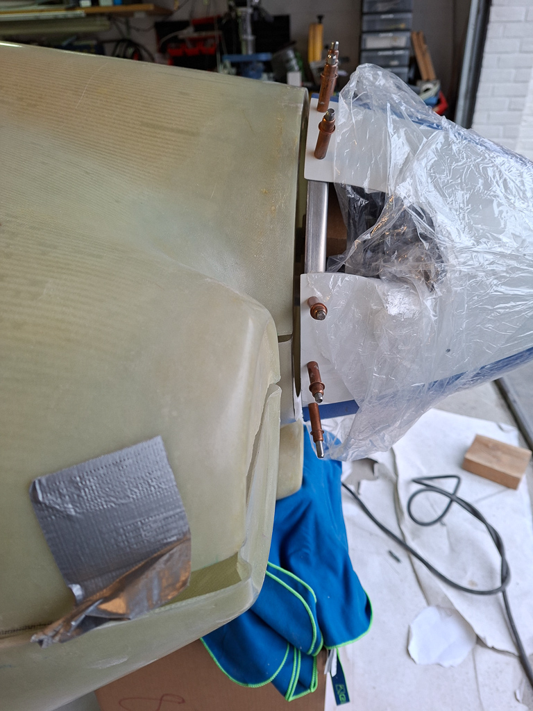
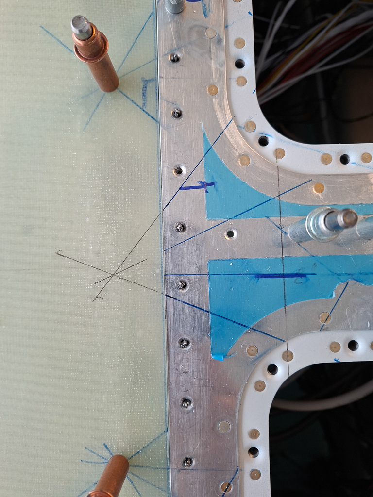
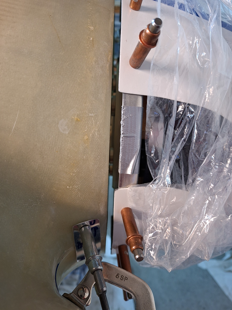
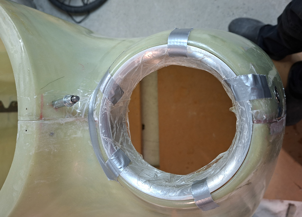
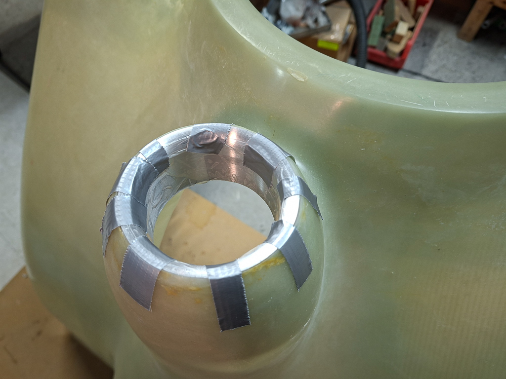
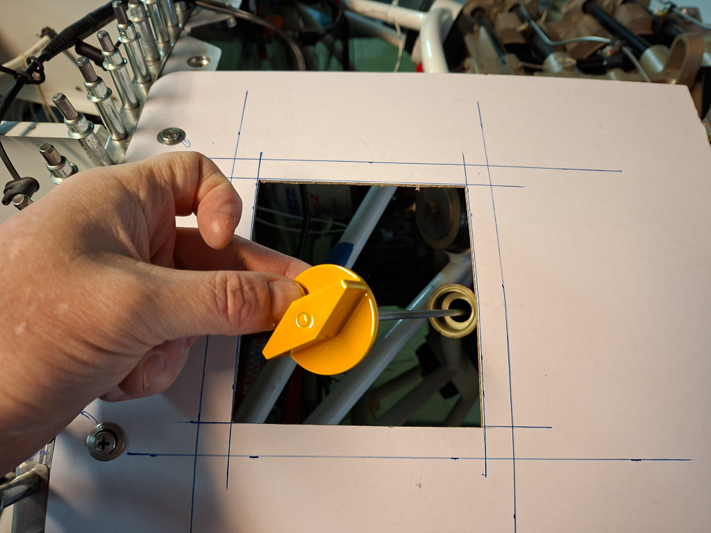
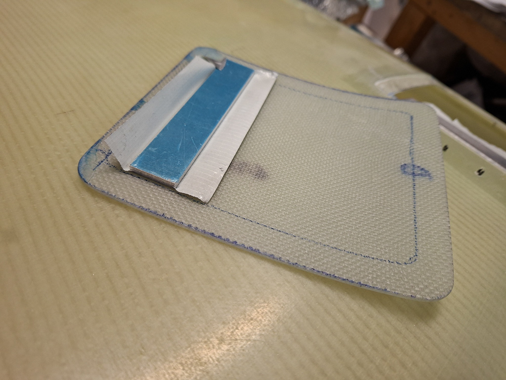
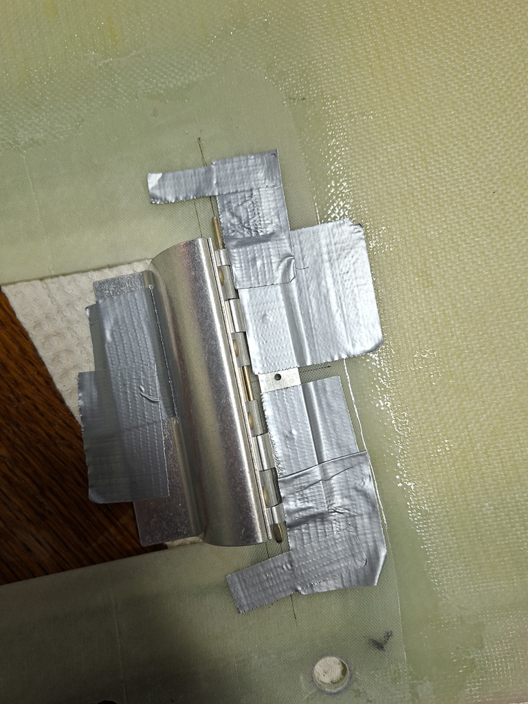
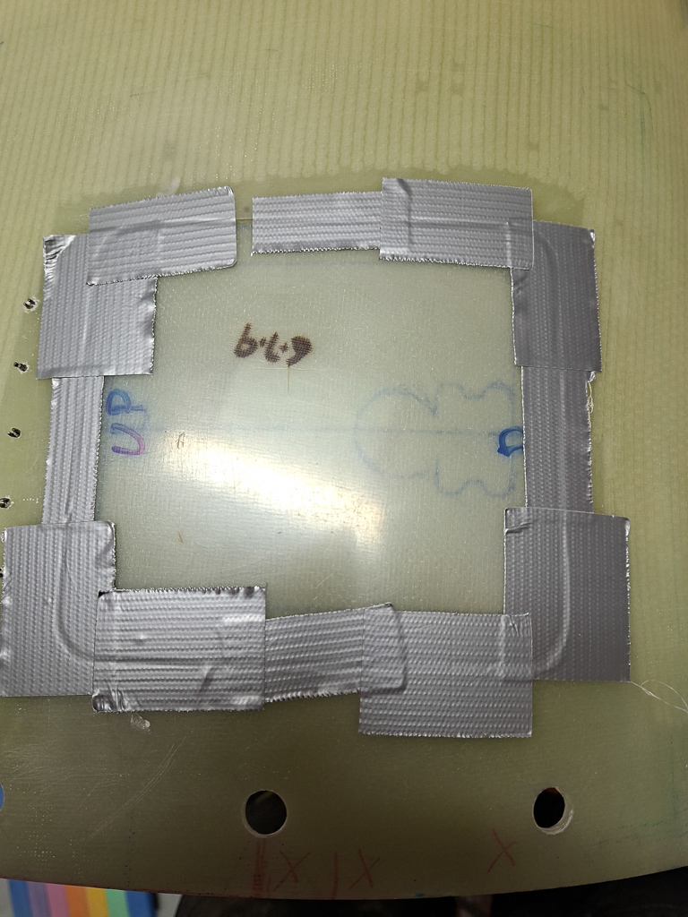
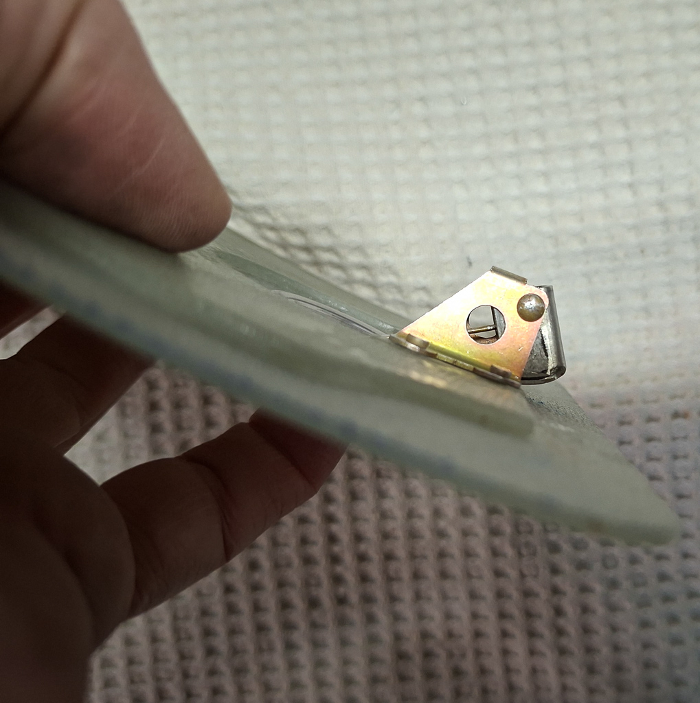
I then centered the safe air pass through kit parts in the hole and taped it with good old duct tape to drill the holes for the 4 screw that hold the part in place.
Deburred holes and all done.
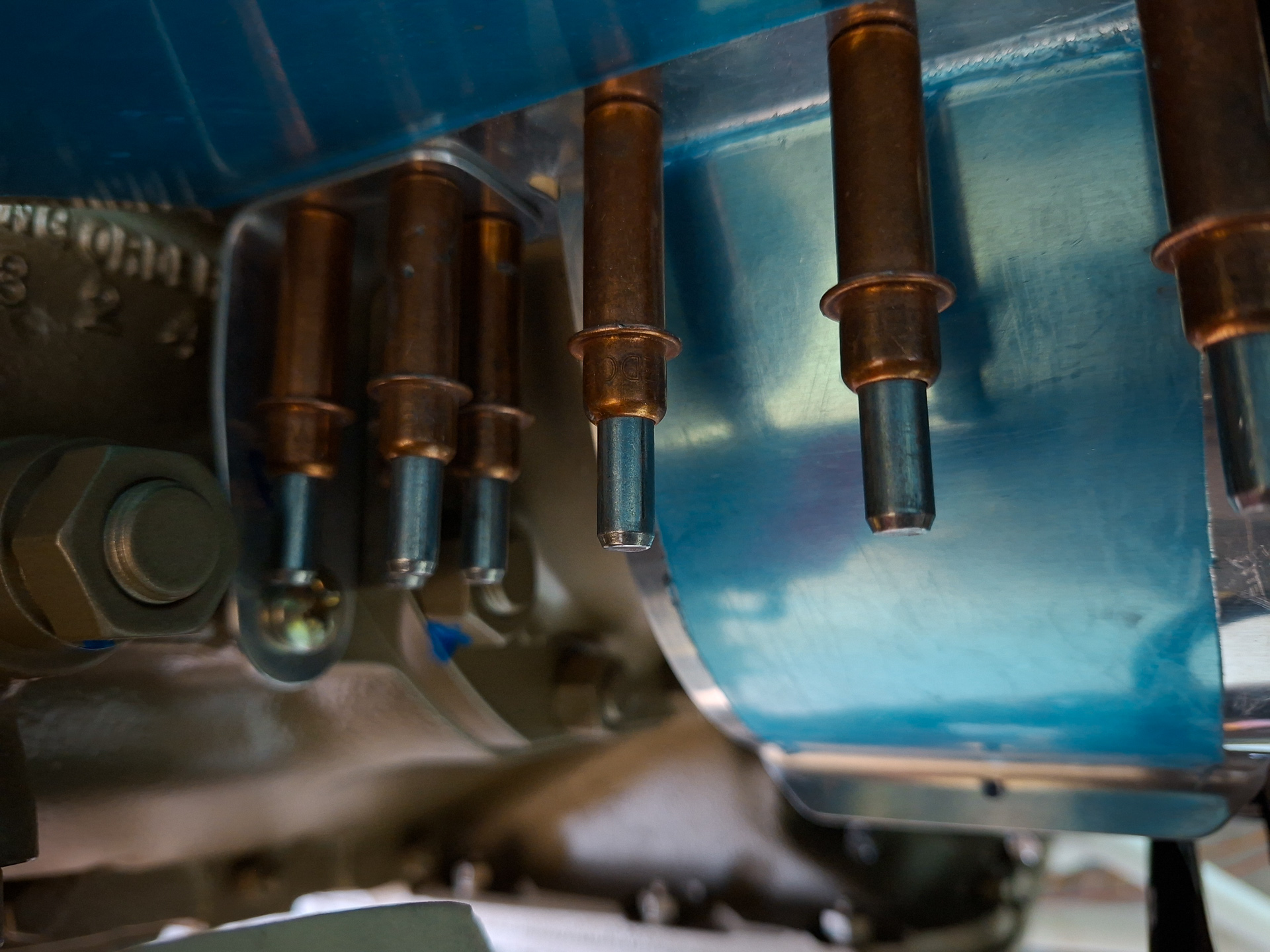
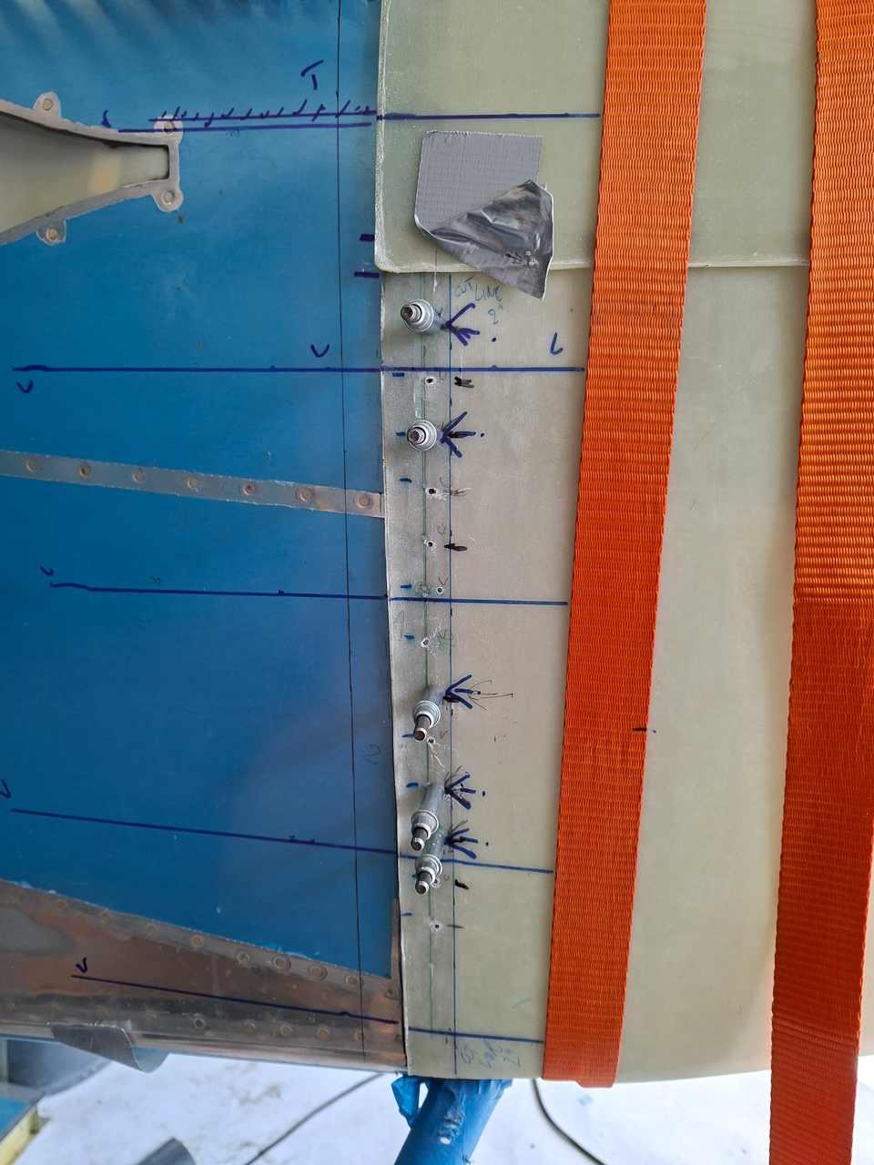
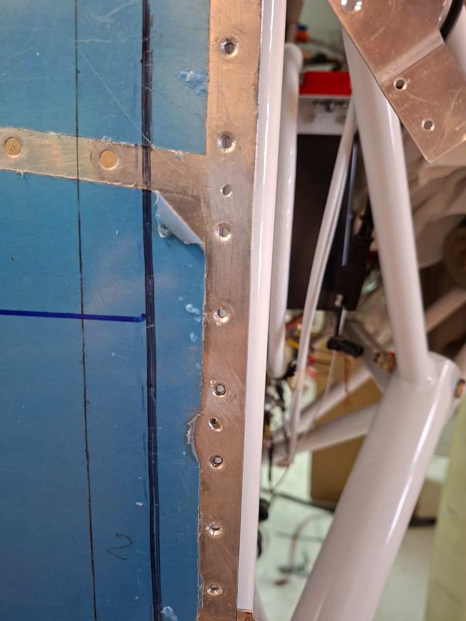
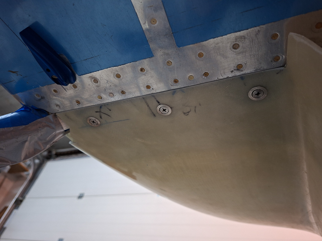
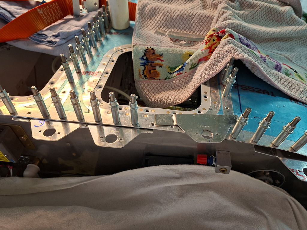
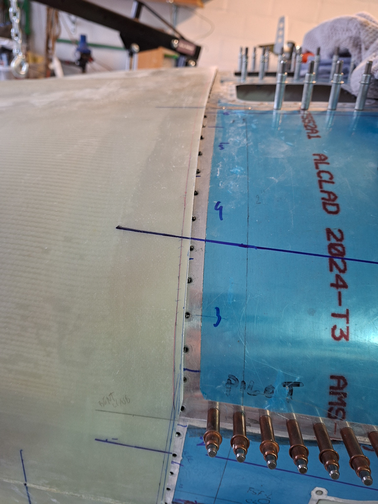
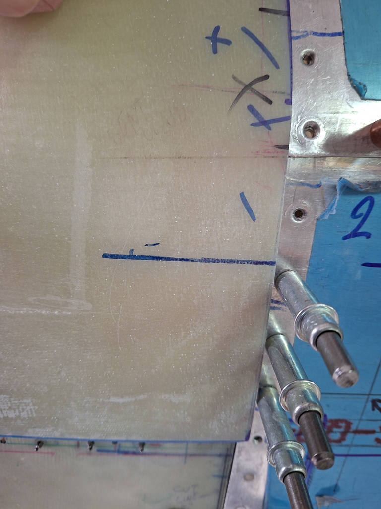
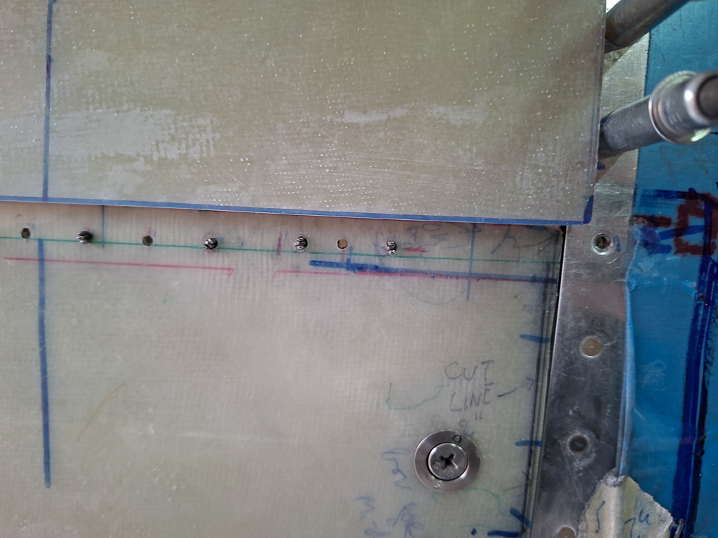
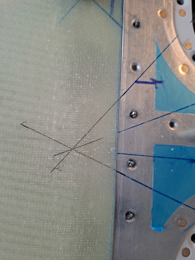
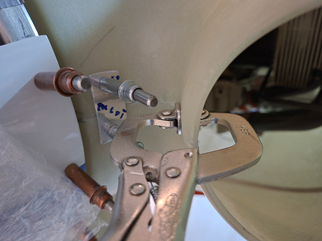
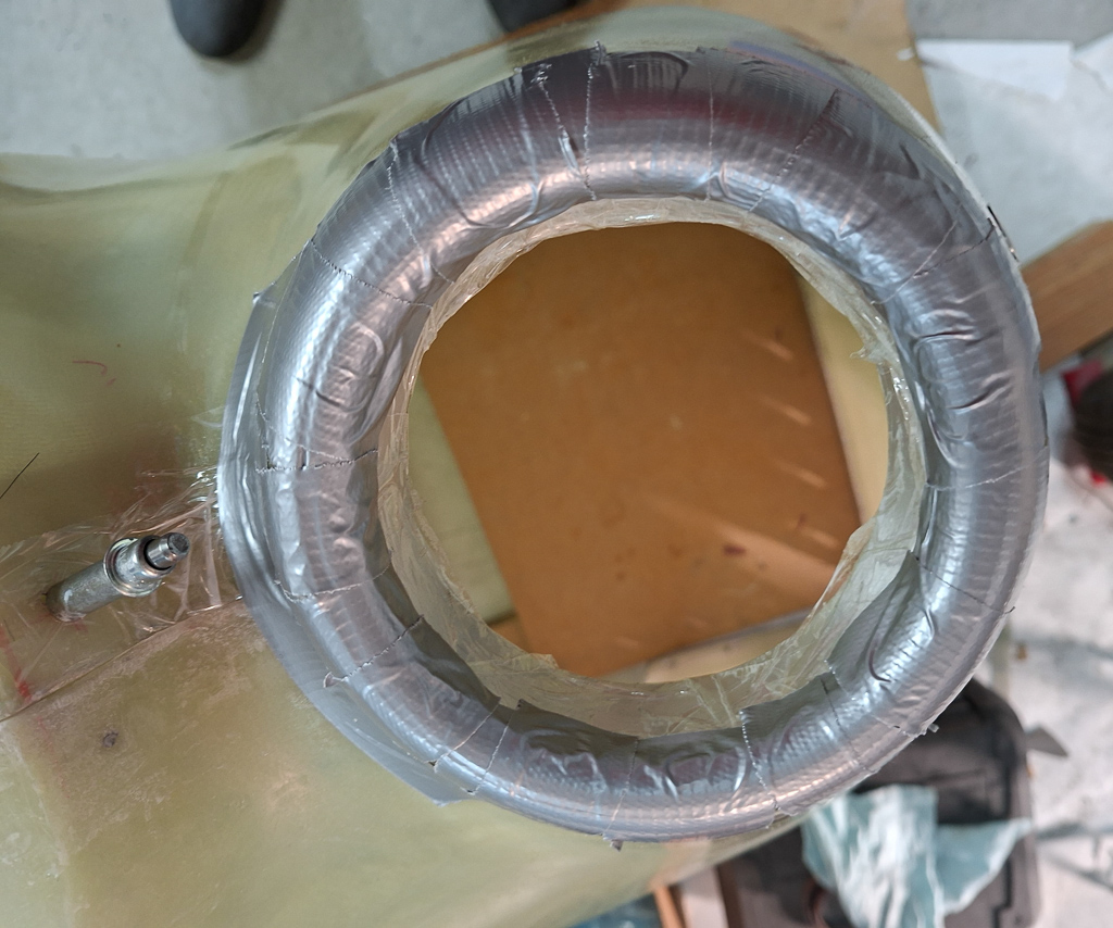
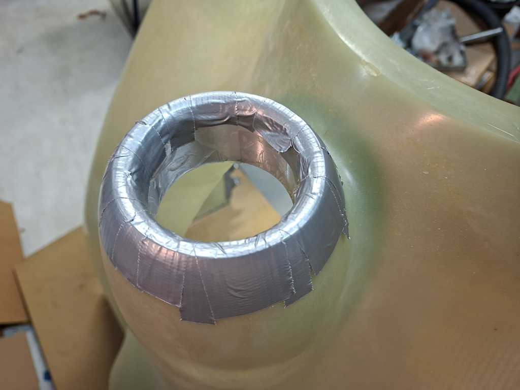
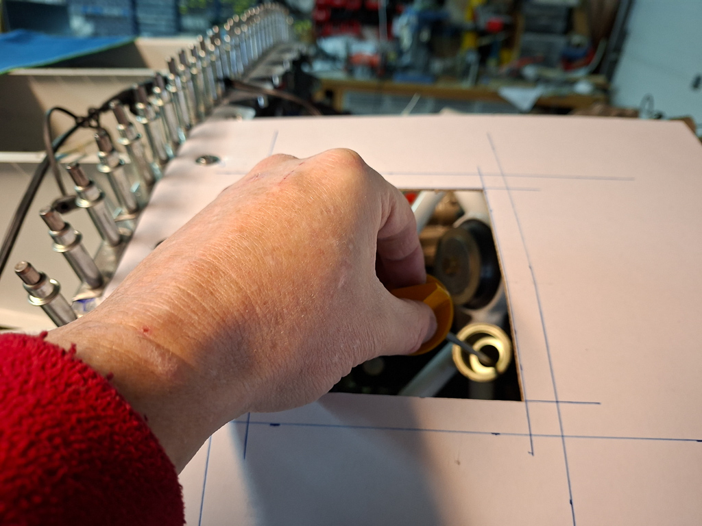
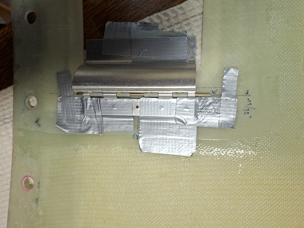
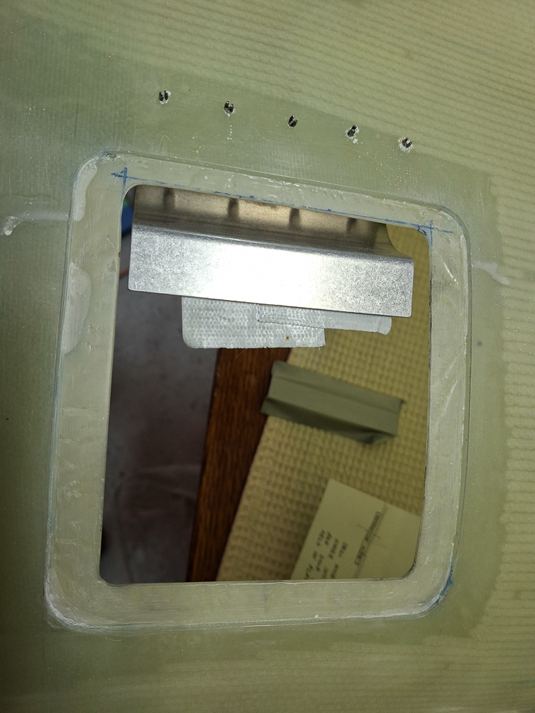
Same precedure on the passenger side. Next image is just after being through with the hole cutter.
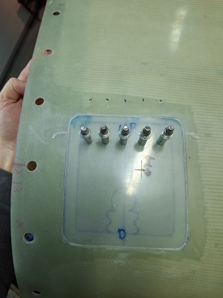
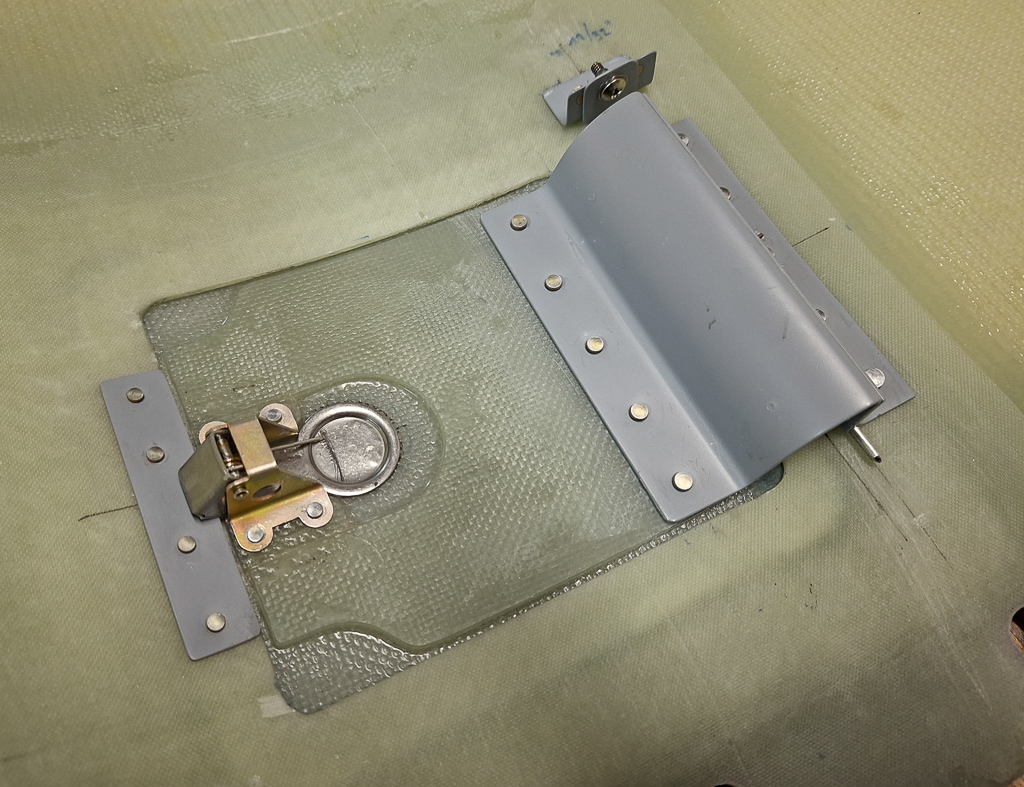
attach holes drilled (not deburred) and temporarily fitting the passthrough ring.
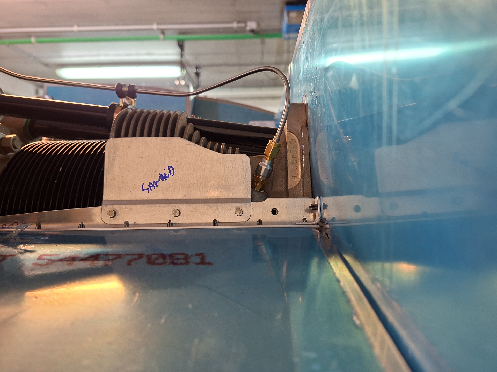
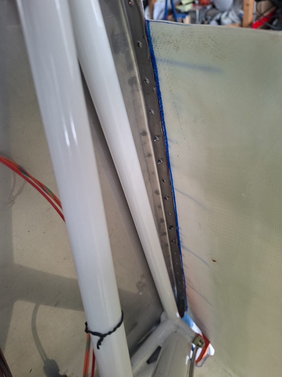
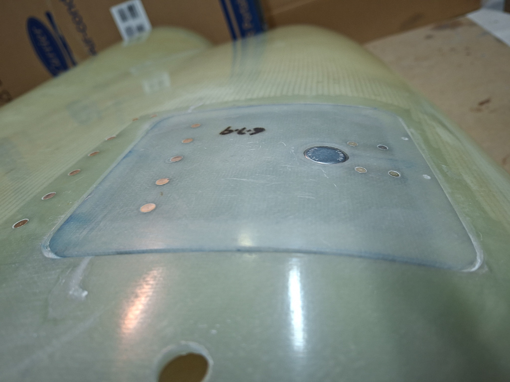
All looking neat and clean. This will finally be installed when my 3M firebarrier paste arrives so that I can finally screw this in place.
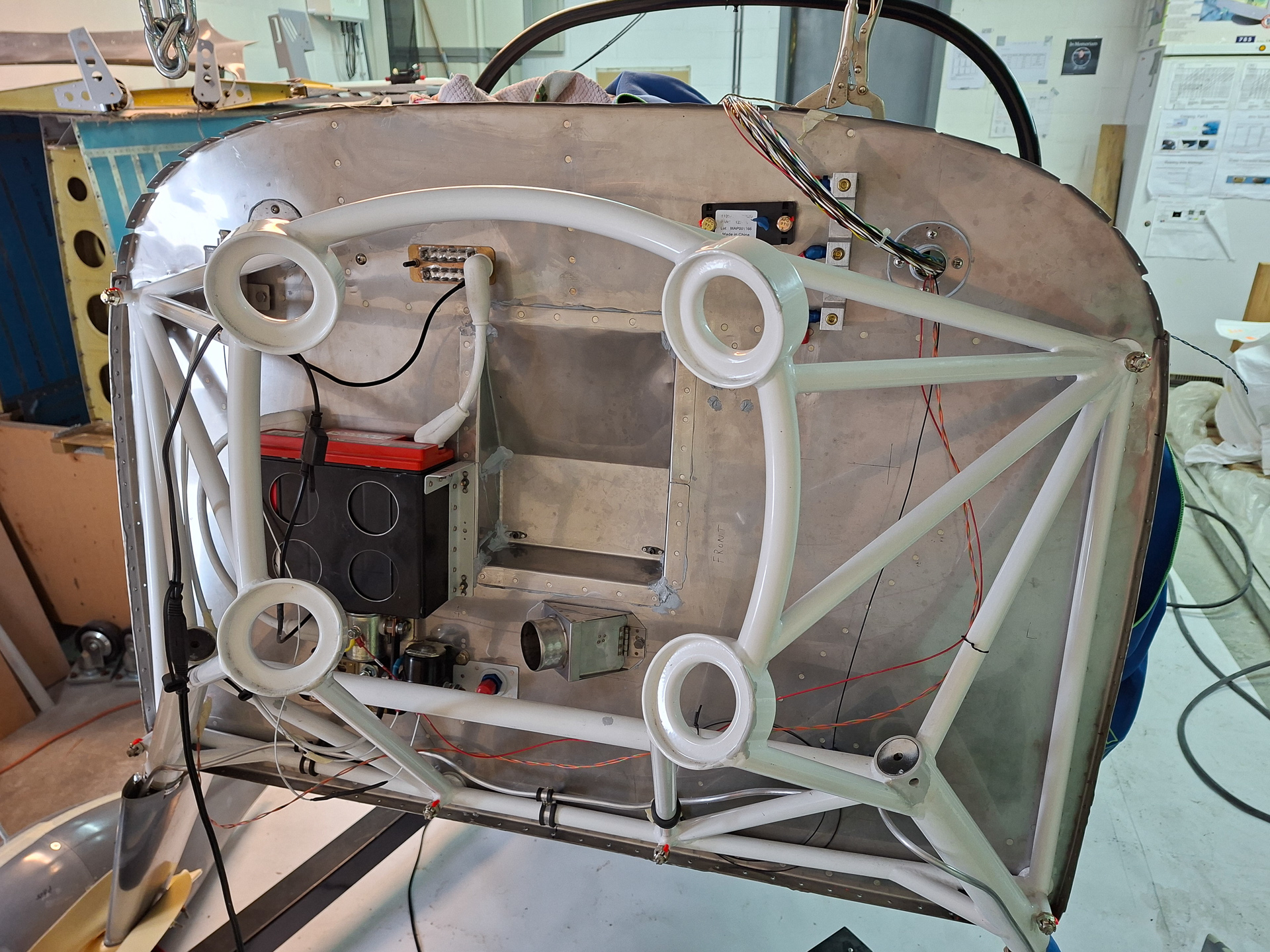
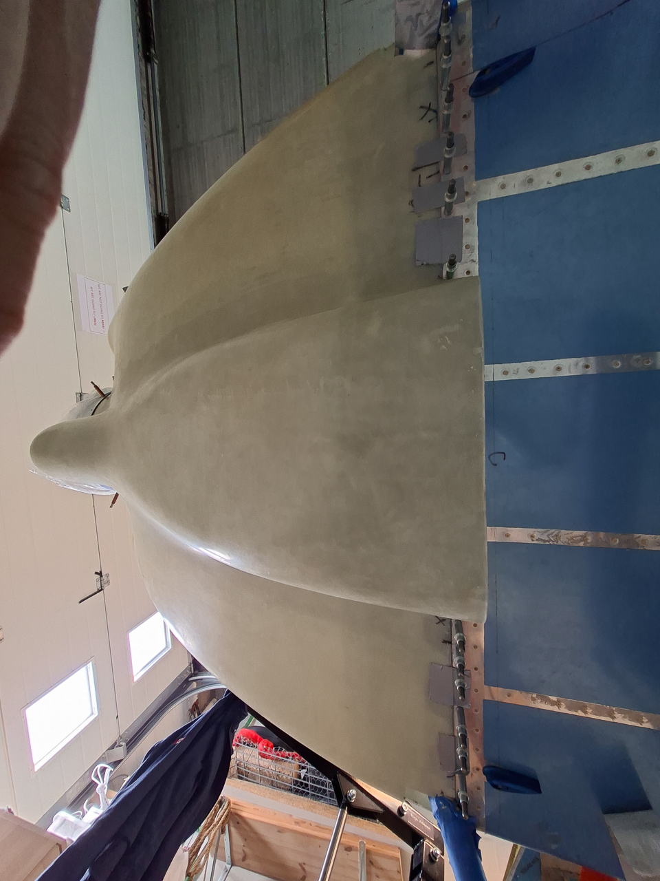
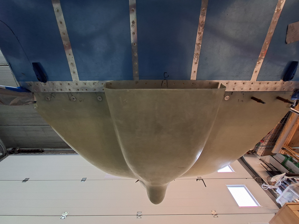
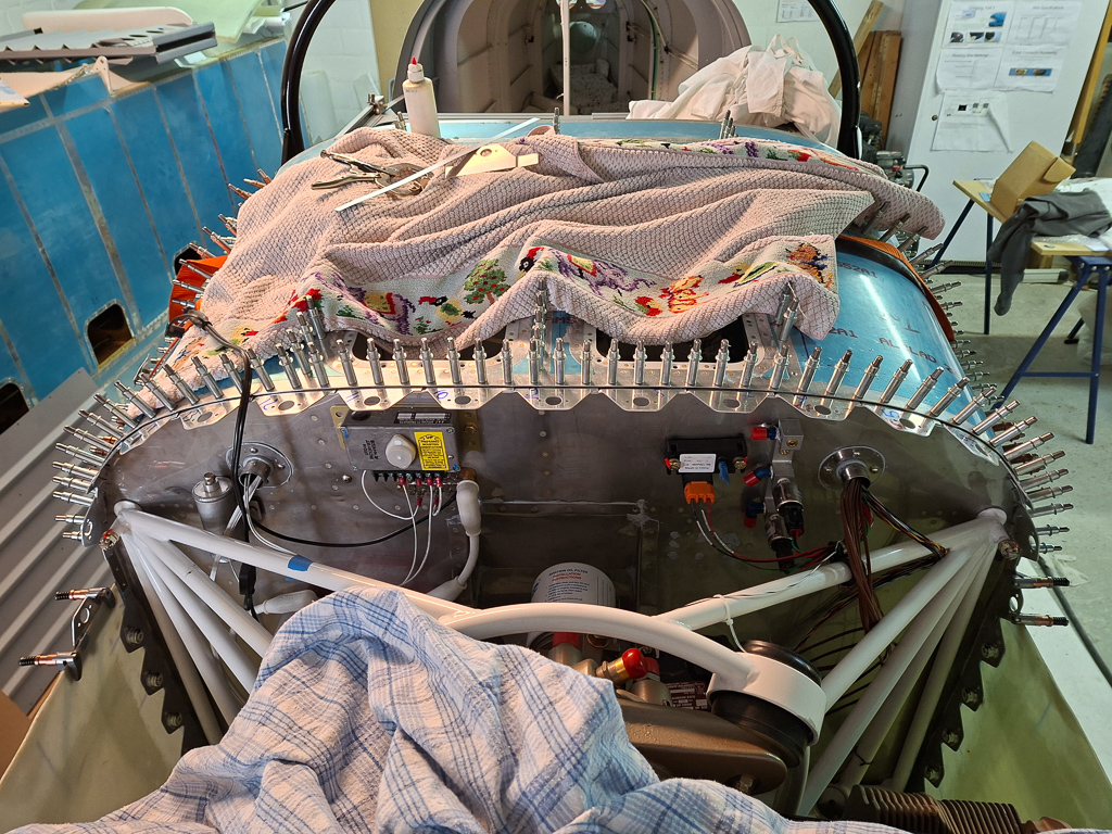
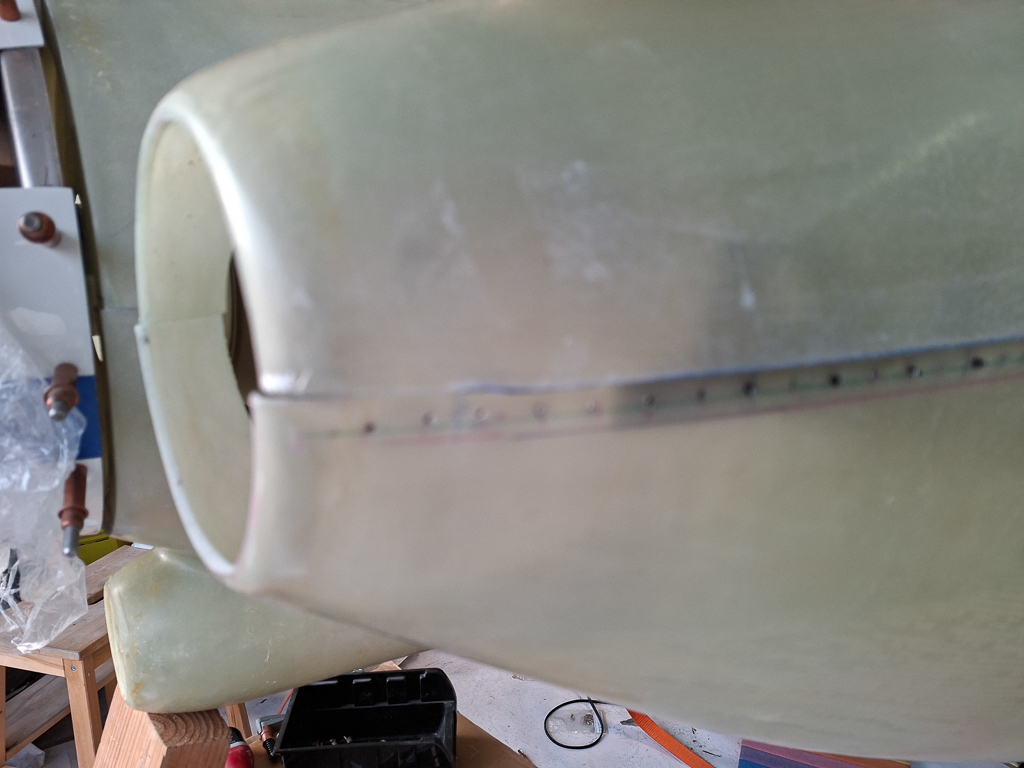
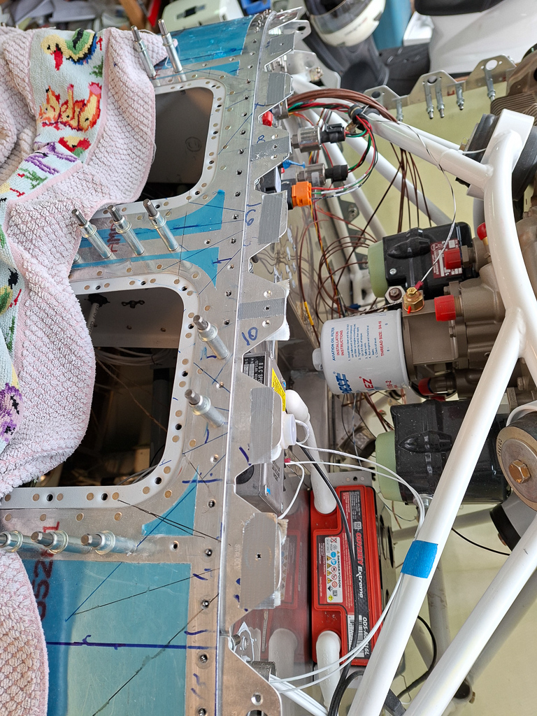
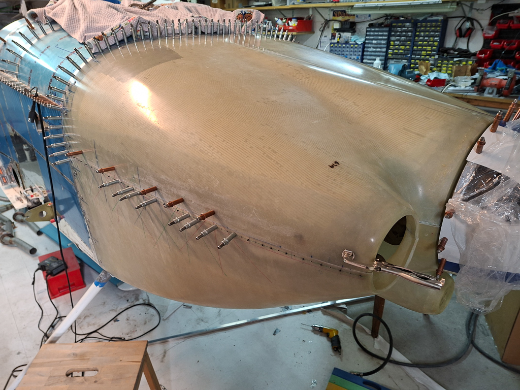
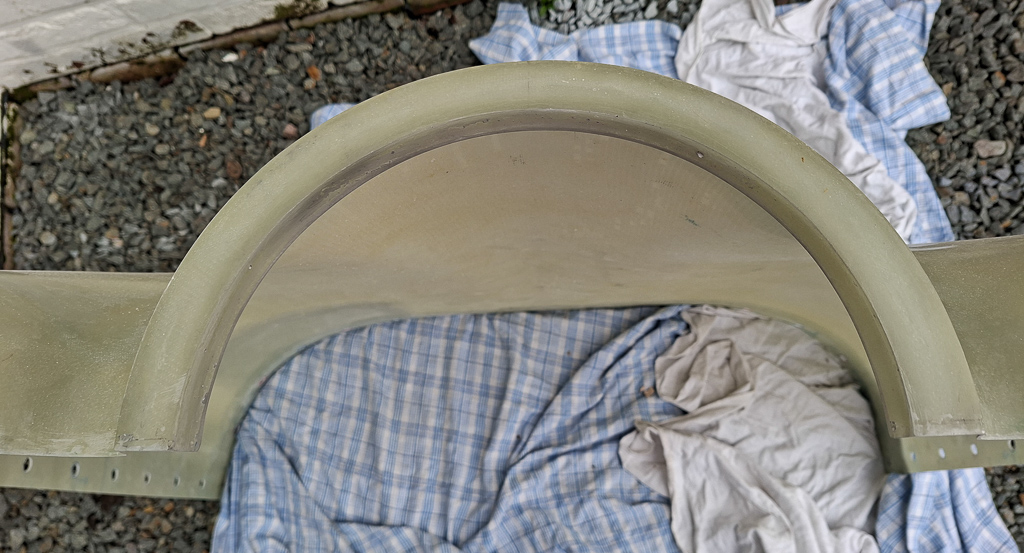
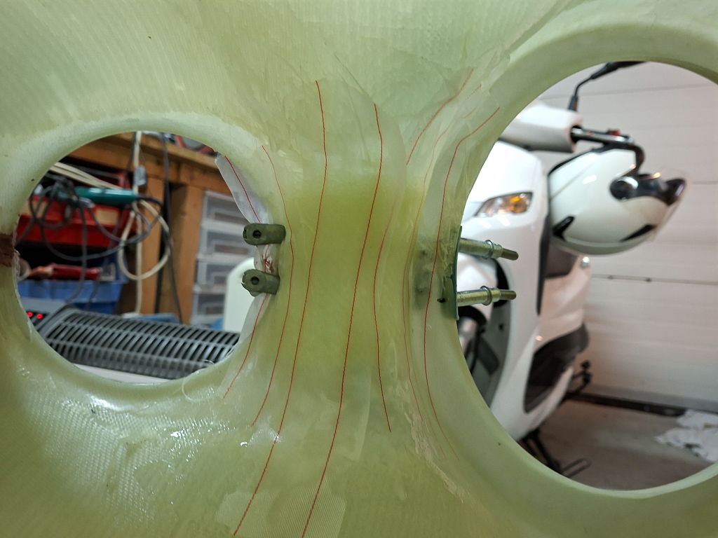
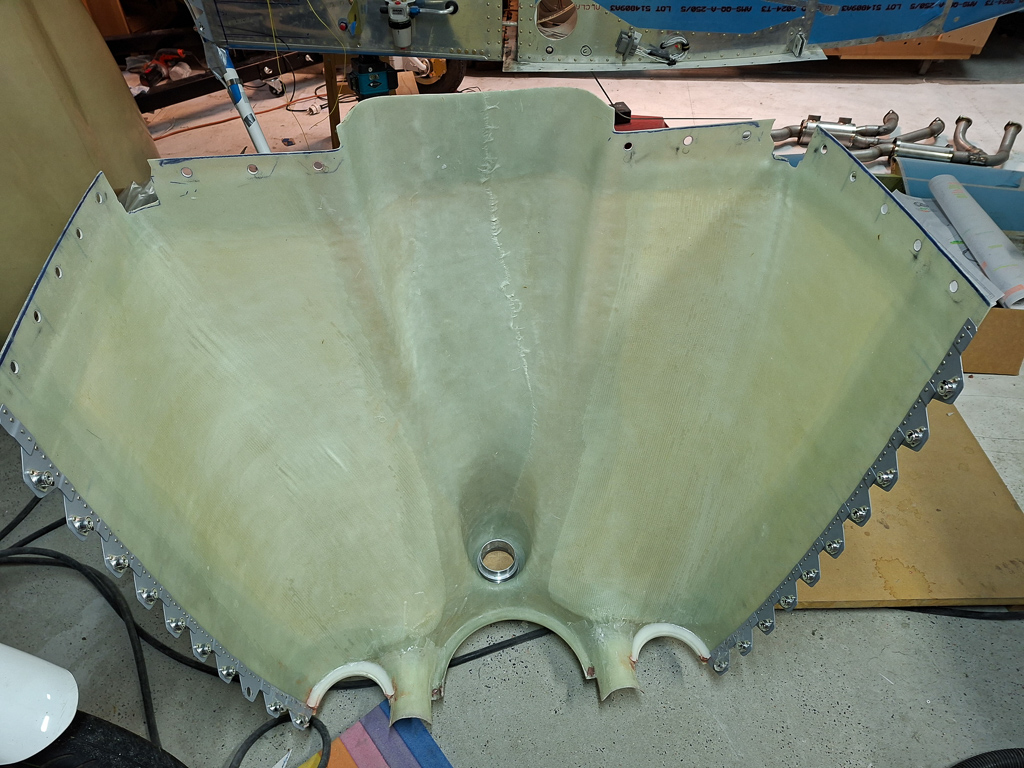
Forward look of the firewall so far with the two holes finished
25/03/2023 - Hanging the engine mount - 4H
It's never really the right moment to hang the engine mount because there's possibly still penetration holes to make later but you 'll only find those ideal spots when the engine is hanging. And no way to hang the engine without a mount. So I figured I had postponed this long enough in order to hang the engine mount. I have also been put the fuselage on it's gear and final installation of the engine mount has to be completed first. Just to clarify, I already had drilled the firewall attach holes a long time ago, so this workday was about final hanging, re-measuring and torqueing the castle nuts with final cotter pin installation. It's a simple process but I found it a big deal as it's the part that will finally enable the start of the gear and engine ffw work. The firewall is attached with AN6 bolts and AN310-6 castle nuts. My smaller torque wrench that only goes up to 150 in/lbs was unsuitable for these so I had to use another larger scale torque wrench. Torque range on these bolts is 160-190 in/lbs. They are fastened with a castle nut and cotter pin. The procedure on these is to torque to minimum value and then thighten till the next castle notch comes available that aligns with the hole. My torque wrench was with ft/lbs and it's a simple conversion of dividing in/lbs by 12 to get the right ft/lbs number. The range here had to be 13.33-15.83 ft/lbs. The image below shows my wrench set to 13.3 for initial torque.
The next image shows all 6 bolts installed with 2 spacers between the mount and firewall at the center bottom.
Some detail images of the cotter pin in place. I needed 3 washers on the top pilot side.
same amount on the top passenger side
only one was required on the bottom side
Next image shows the spacers and also one washer.
another image of the cotter pin installation.
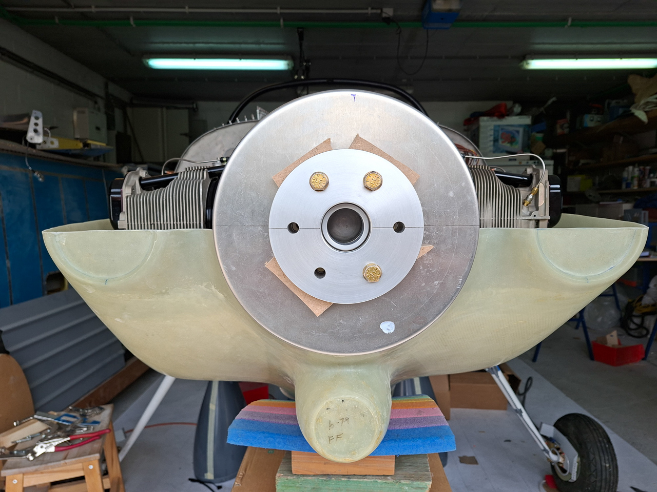
Top view engine mount
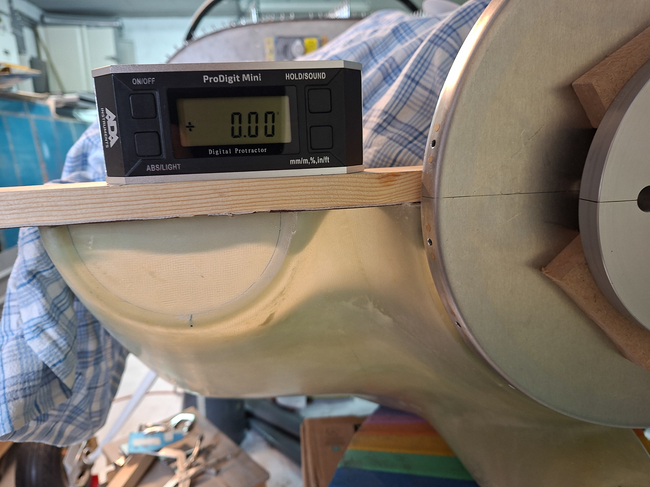
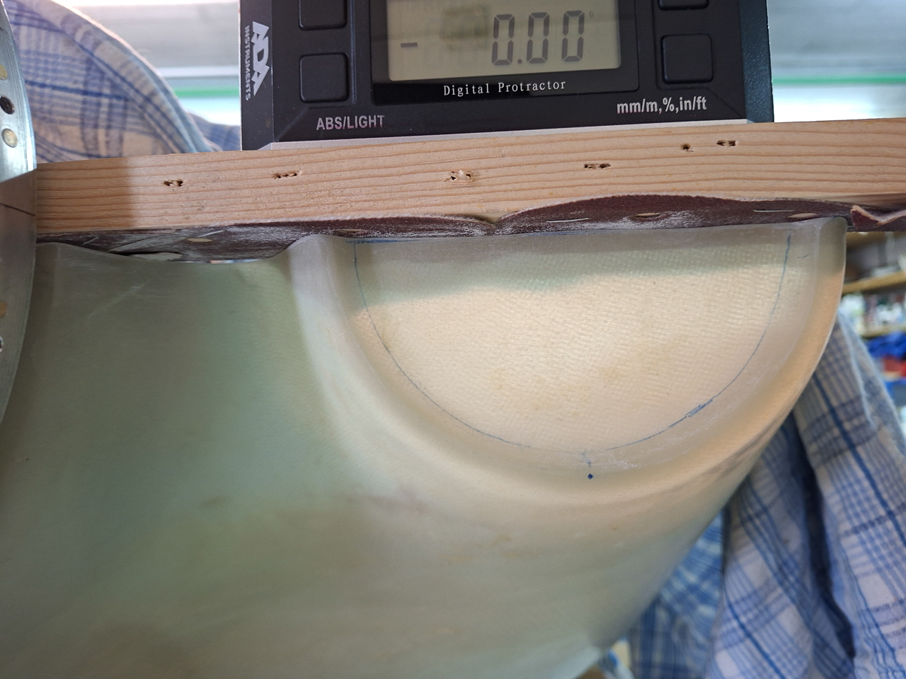
Forward view with the level in place showing a 0.00° level mount.
05/02/2024 - Visit PMM Wings for engine - 4h
The day has come to take some final decisions on buying an engine. I had an offer in 2019 from PMM Wings for an engine and this was more of a ballpark figure request for a Superior IO360.
Later on I was tempted to go with the reduced price offer for a Lycoming IO360-M1B engine through Vans. Lycoming gives discounts for kit builders if purchased through Vans. After 2021 covid and the current inflation 2023 figures, prices have gone ballistic and they aren't really coming down. On the contrary, further increases are expected as especially cylinder availability is dramatic.Prices compared to my offer from 2019 have gone up 40% ! So waiting longer will only increase the total cost.
At some point I got tempted to go for a used second hand engine and buy second hand or overhauled. I went on planecheck, trade-a-plane and barnstormers and such sites but soon got demotivated. Most of the engines for sale there have had accidents or major issues. You have to be an expert able to assess what you see on photos or during a visit and I'm afraid I don't have those skills. The nice ones which were also not priced excessivly turned out to be scammers trying to rip you of. So I gave up on the idea and turned back to the idea of buying through Vans. A fellow builder did the same and was quite happy with how that went.
My main problem with the engine purchase is "time".Or stated differently, not having enough of it to complete the plane fast enough not to get corrosion risk on the engine.
I can only work half time on the project and I learned from Lycoming support that the waranty on factory engines for corrosion is 6 months. The are pickled and oiled for long preservation but even then they only give you 6 months. I called a lycoming support technician on the phone and he said 12 months is probably fine if you don't live near the coast and humid wet salty environments. The absolute max he recommended is no more than 18 months. 2 years would be too much. Fact is that the engines coming from Lycoming through Vans have been running on the test bench and have had their cylinders run in. So no way around this ticking clock.
Some time later, Vans went through a rough period with a restructuring and chapter 11 scenario and this made me hold of from making the M1B order with Vans. Fortunatly for me, this brought me back to Patrick Van Dooren at PMM Wing Service to discuss options and asking them for a price quote. I was convinced at first that this would turn out much more expensive.
I called Patrick at PMM Wings and explained him my time issues. He mentioned to me that the best way to proceed is to have the engine build without test running. In that case, the parts don't corrode and behave the same as if they would be in his stock. After assembly, I would be able to pickup the engine, do all the fitting, hanging, baffling, cowling etc until the plane is close to completion. Then disconnect it and take it off the mount, bring it to PMM where there will test run it. From then on the time starts ticking again but there won't be the pressure during the FFW building process. I kind of liked this idea.
Additionally I wanted my engine at a certain price. He asked for a quote for a new XP Superior engine IO360 with cold air sump and horizontal induction (which was my initial choice of engine before moving to the Vans Lycoming OEM story). To my surprise, the offer was almost priced the same as the Lycoming IO360 M1B as if I would buy it from Vans and import it myself to Belgium.
Buying at PMM would have the additional advantage of having a service center and warranty close by.
Superior has had some issues in the last year with their crankshaft parts (not being able to produce and deliver) and have stalled delivering engines for quite a while. Availability is also an issue off course as I want to start working on my FFW next year.
PMM will deliver the Superior engine with a certified Continental crankshaft inside to replace the superior crankshaft. It's promised to be arriving in the PMM hangar by November, to be assembled in December. End of 2024, it would be ready for pickup.
So the final choice has become a new experimental Superior XP IO-360-B1AD2 engine
New Superior Cylinder Kits
New Roller Camshaft and roller tappets
New magneto’s Champion with 2 impulse couplings, new Fine Wire Spark Plugs & Ignition Harness
New fuel injection system horizontal front mounted with cold induction oil sump
180 HP @ 2700 RPM, fixed pitch prop configuration
Engine will be assembled and tested at PMM
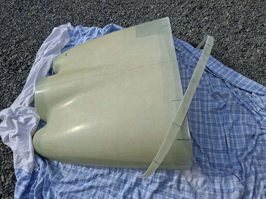
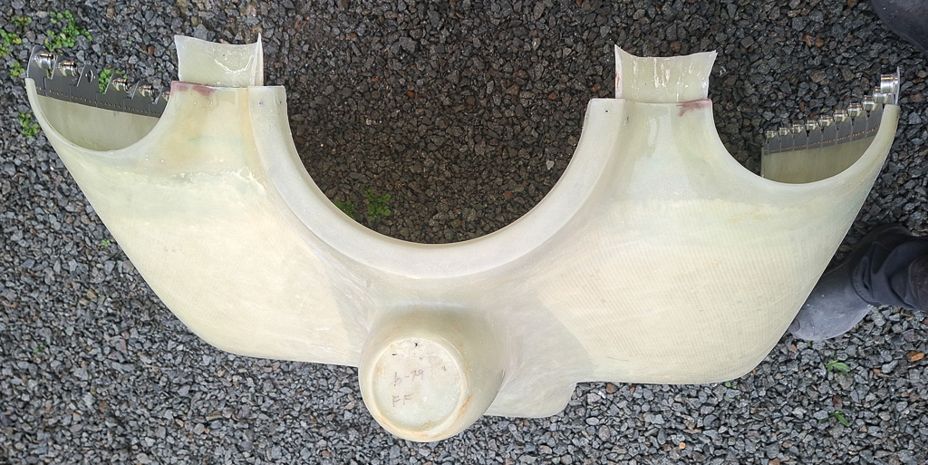
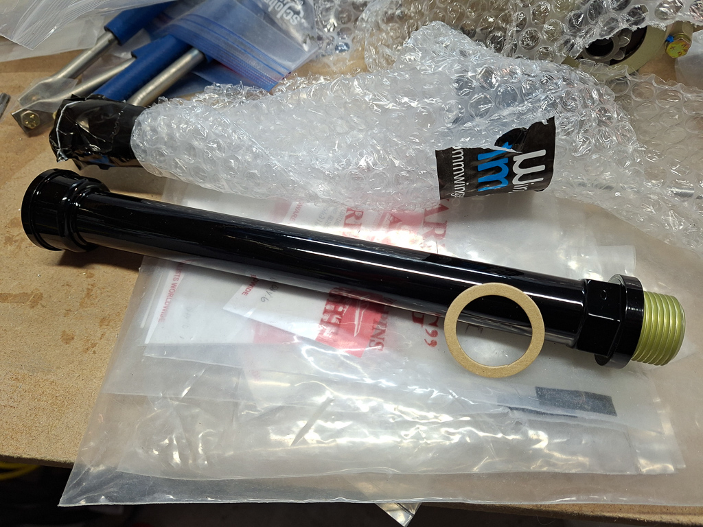
17/05/2024 - Sam James Cowling arrived
A new box arrived, it's always fun receiving new goodies in the workshop. Although it will take a while before this can be iinstalled, I'm glad that I finally took some decisions on FFW side. This time it's the Sam James Long Cowl that arrived. Very nice and helpfull people at Sam James and they were very patient with the many questions I had.
After unboxing, I stored the cowling in the upper room.
I also ordered the plenum and the MK2 air filter as I will have ram air horizontal induction.
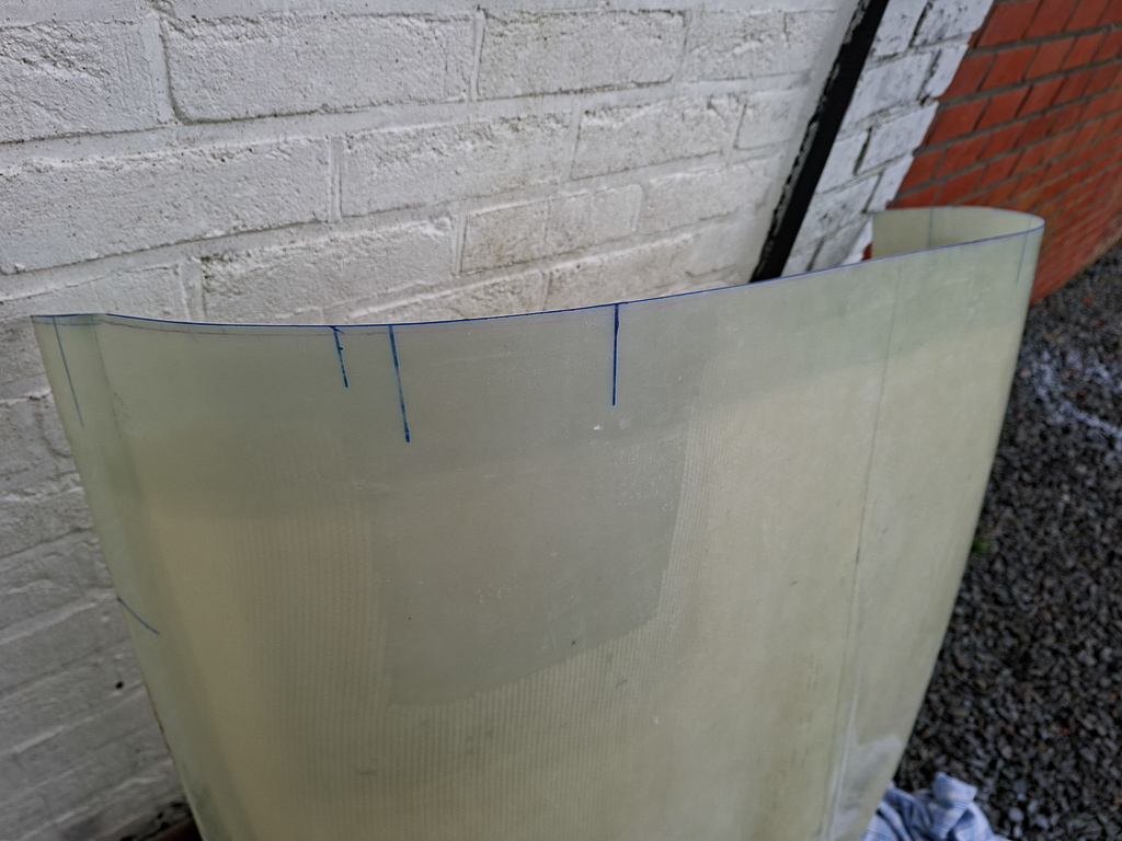
Her's my shippment list.
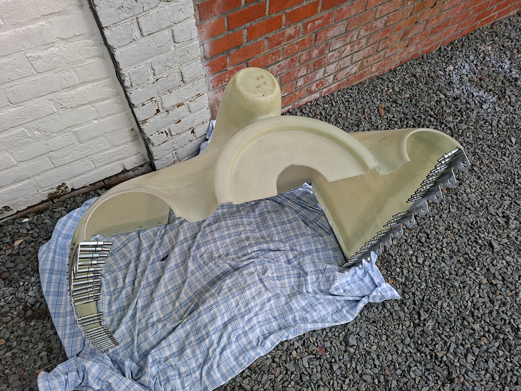
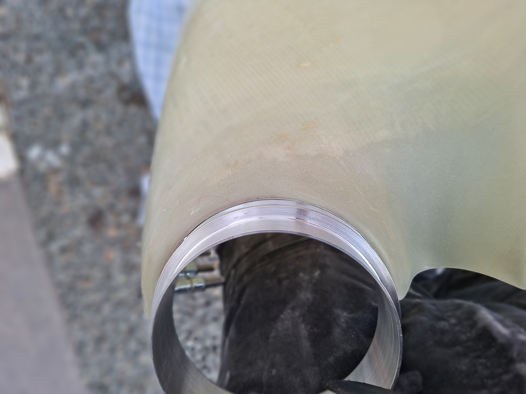
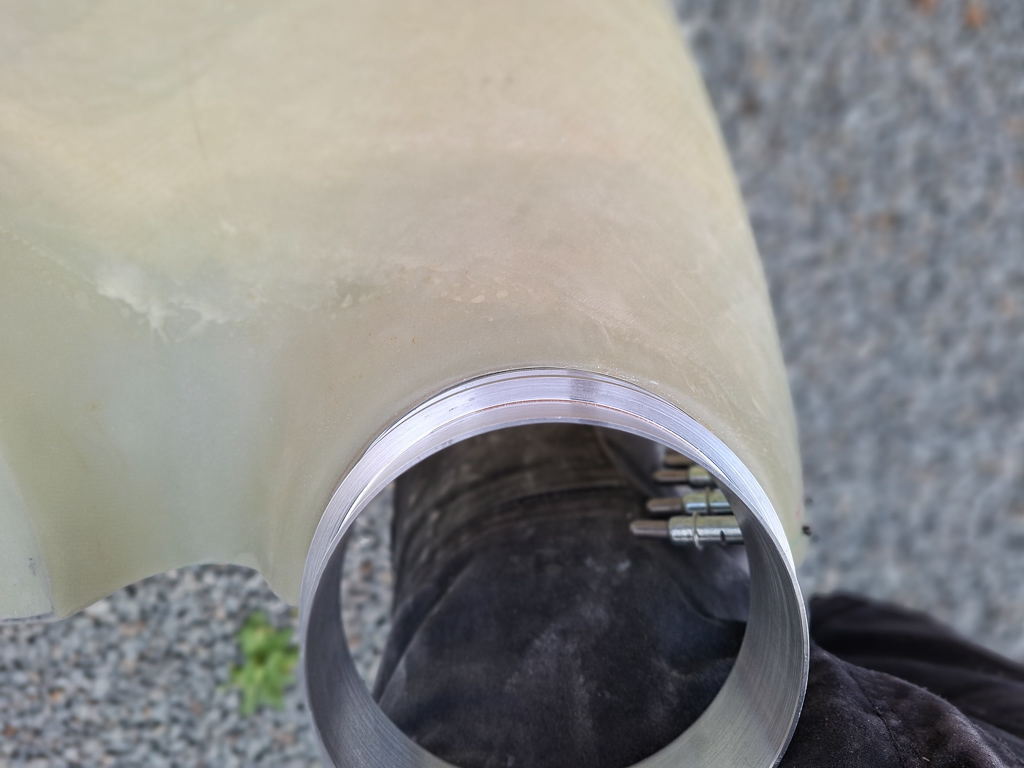
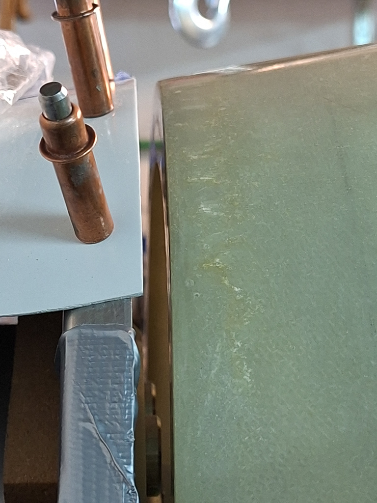
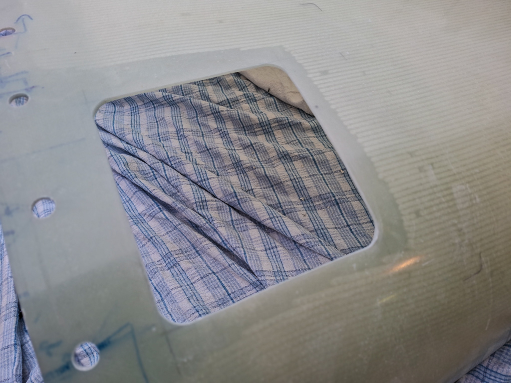
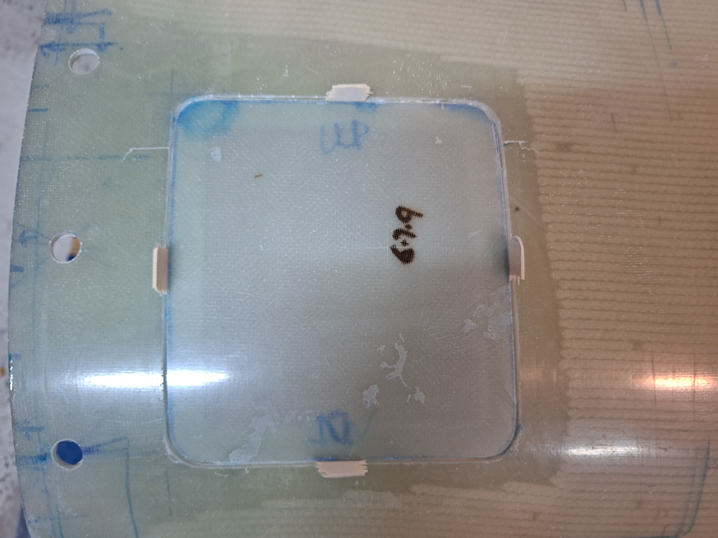
This is the content of the second box. Some neoprene and more plexi glass items together with the alumnium rings for the forward side of the cowling intakes.
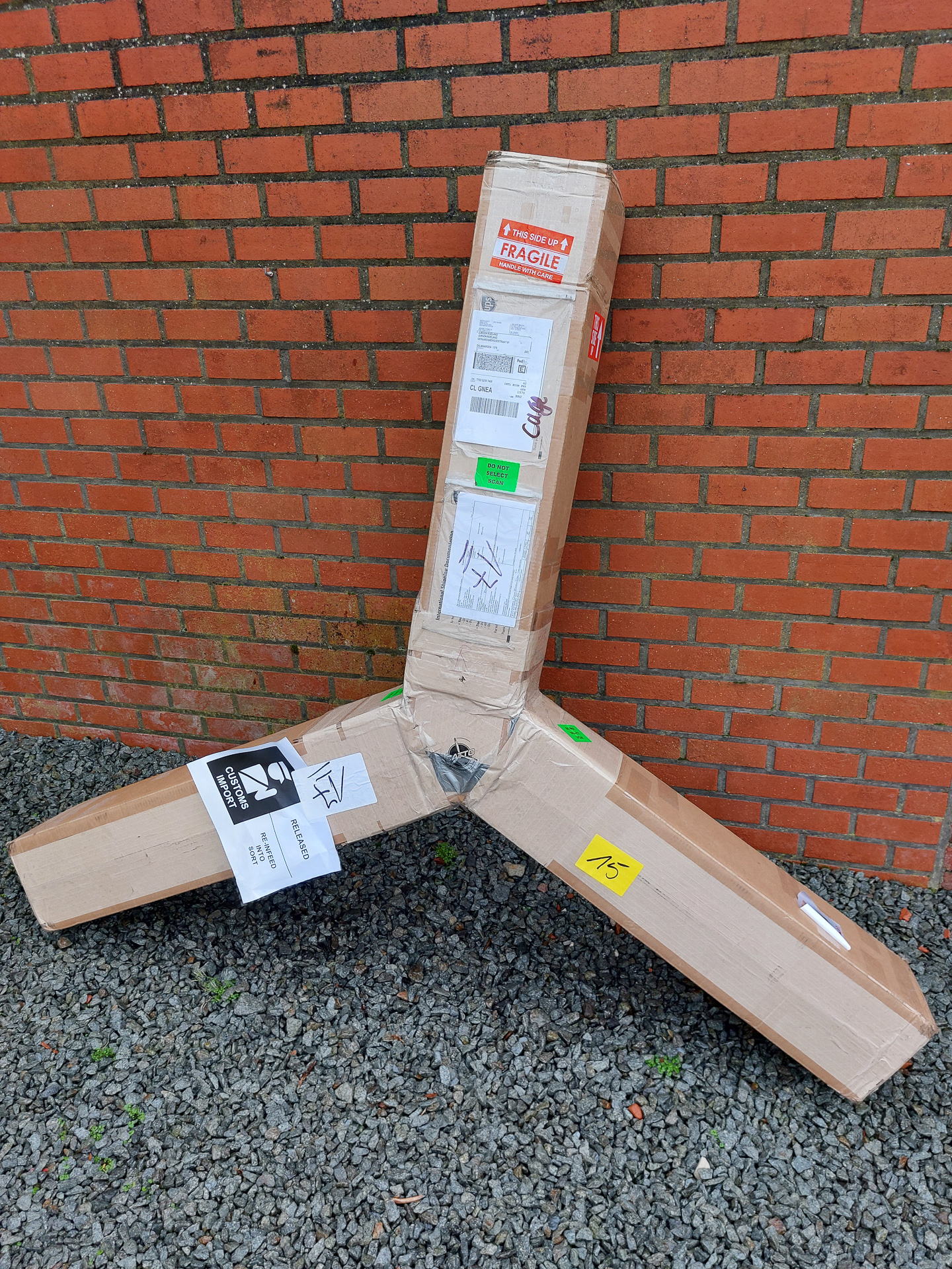
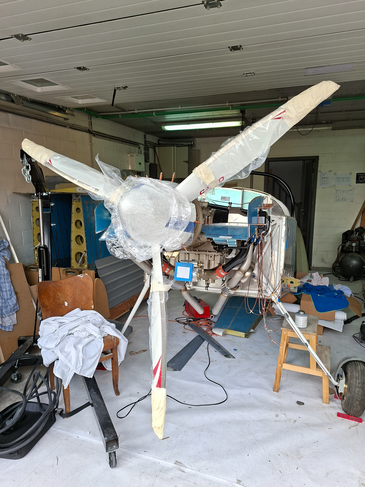
01/12/2024 - Catto prop arrived - 1h
Short article for an exciting moment. After many years of dreaming of a 3 bladed catto prop, I took the decision 3 months ago to buy it and today, it finally arrived home. I have long time hesitated because of the shipping cost of the prop from the US to Belgium. After all the shipping cost was reasonable, even though it was sent by air.
I can recommend everyone to work and do business with Craig and Nicole Catto.
Not only are the catto props one of the most loved propellors used on RV aircraft, they are superb people and helped a lot in the decision process. They very patiently answered my ton of questions as a newbie and helped me find the most cost efficient way to get my order shipped to Belgium.
Unpacked it and verified for any shipping damages. The way the prop is packed is very safe. The box is full of foam and the reinforcements inside support the carton box.
Couldn't resist taking a picture with my new toy. The plastic was still on but you can kind of see the red tips through. This thing is remarkably lightweight. Weight and balance will tell if I need a weightplate in front of the prop once installed.
As I have a Sam James aftermarket cowling, I also needed the sabre plate extension.
This is the rest of my order:
Spinner Kit 13" Primer
Catto 13" Spinner Kit. Includes fitting of cutouts, tracking and drilling of mounting holes.
Carbon Fiber Spinner with aluminum front bulkhead and aluminum rear bulkhead.
Primer or Carbon: Painted White
Saber 4" 360 Kit
Extension 4 in. long, 7 in diam, 12-hole, SAE- 2, 1/2E.
A little Christmas present arrived at my door today.
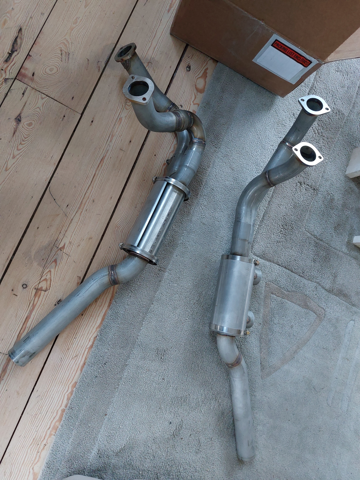
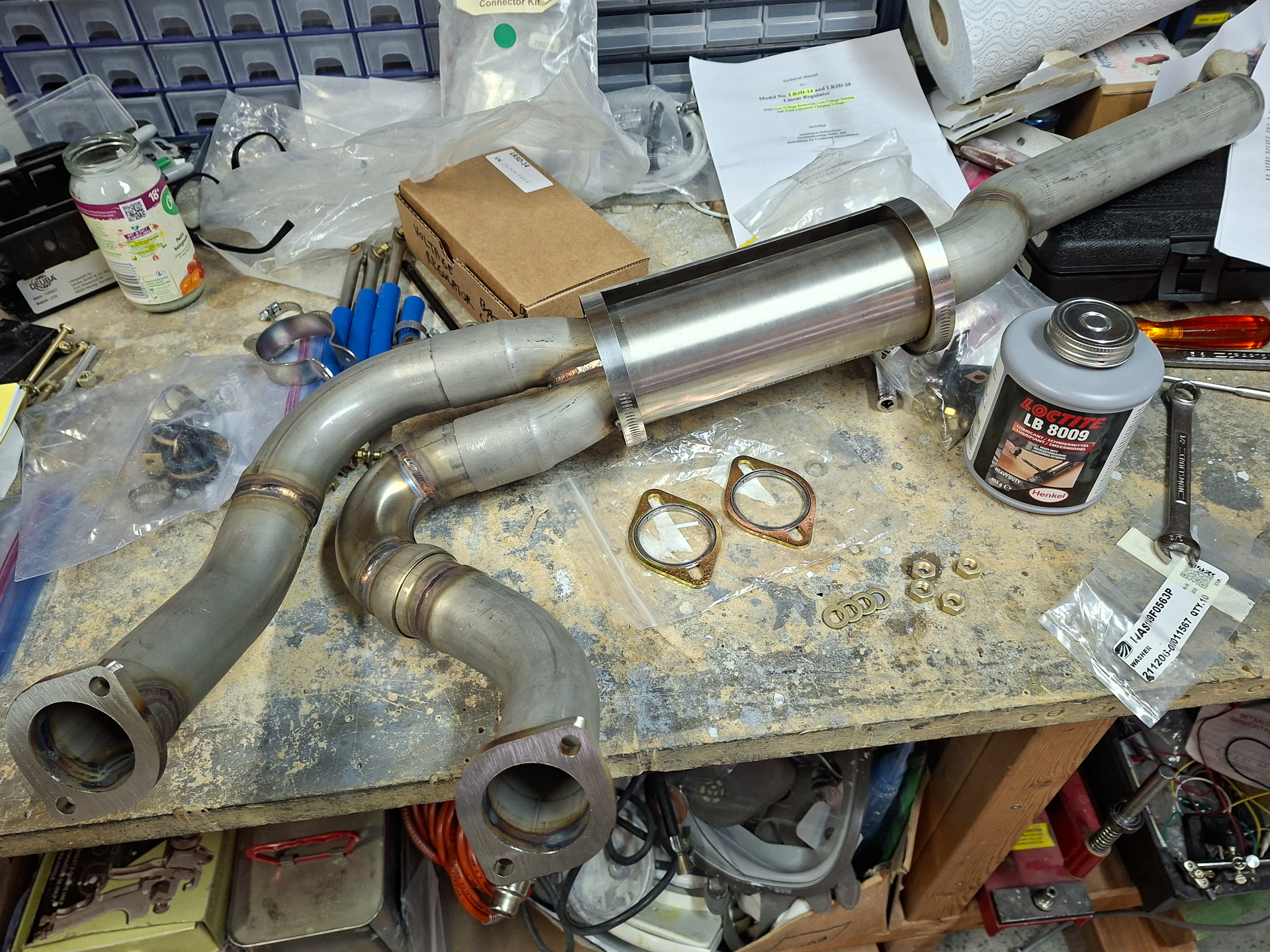
The Vetterman side-by-side Exhaust system.
I ordered this back in September and it took a while, but finally it's here and ready to be used. All we need now is the engine. I had some calls with Clint from Vetterman. He is hard to get a hold of as he's a very busy man but once you get him on the phone he is all help and idea's.
Choosing the right exhaust system was a long process full of doubts and questions. I finally opted for the side-by-side pipes instead of a standard crossover system. Reason being that I have a Superior engine with a cold air sump and the Sam James Cowl.
Additionally, you have to keep in mind that in Belgium and most countries in Europe, noise abbatement is a very important issue.
An RV7 falls into the aerobatic category and these planes fall in the category where a noise certificate is not legally required. But then, how good is this advantage as soon you won't have anymore small airports where you are allowed to visit. Additionally you always pay the highest landing fees because of the noise tax. This made me decide that I do want the mufflers so that at least noise gets reduced to a minimum. The 3 blade Catto wood prop will also add a little noise reduction over a standard 2 blade aluminum propellor.
A cross over is not possible with mufflers on my engine and cowl. It just doesn't fit due to the sump. I then visited a meeting at Breda Seppe airport of the NVAV folks and Joop St Jago was so kind to show and explain his configuration in details. He also has the Sam James cowl and a Superior engine and he did have an exhaust system from Vetterman installed with mufflers. The solution is in the side by side exhaust. I called Clint from Vetterman again and he told me that even the side by side with muffler would not fit the Sam James cowling.
That's true, but Joop showed me how he solved that on his RV7. He cut two rectangles out of the bottom cowl and made some custom extensions that allow the mufflers to be installed. Once painted, they are hardly visible and the side by side configuration makes also for a nice setup.
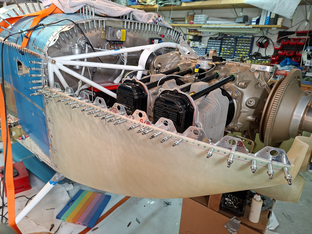
23/04/2025 - Engine assembly day at PMM (part 1) - 7h
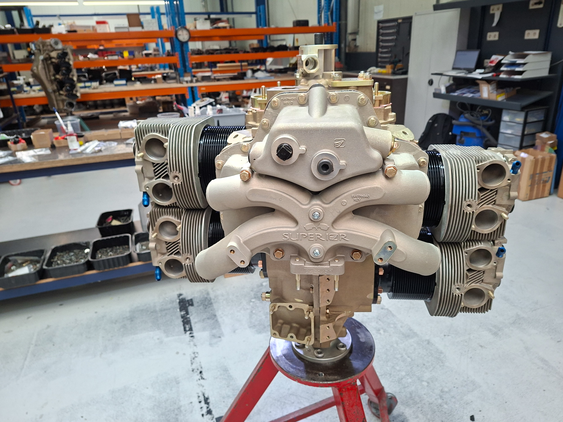
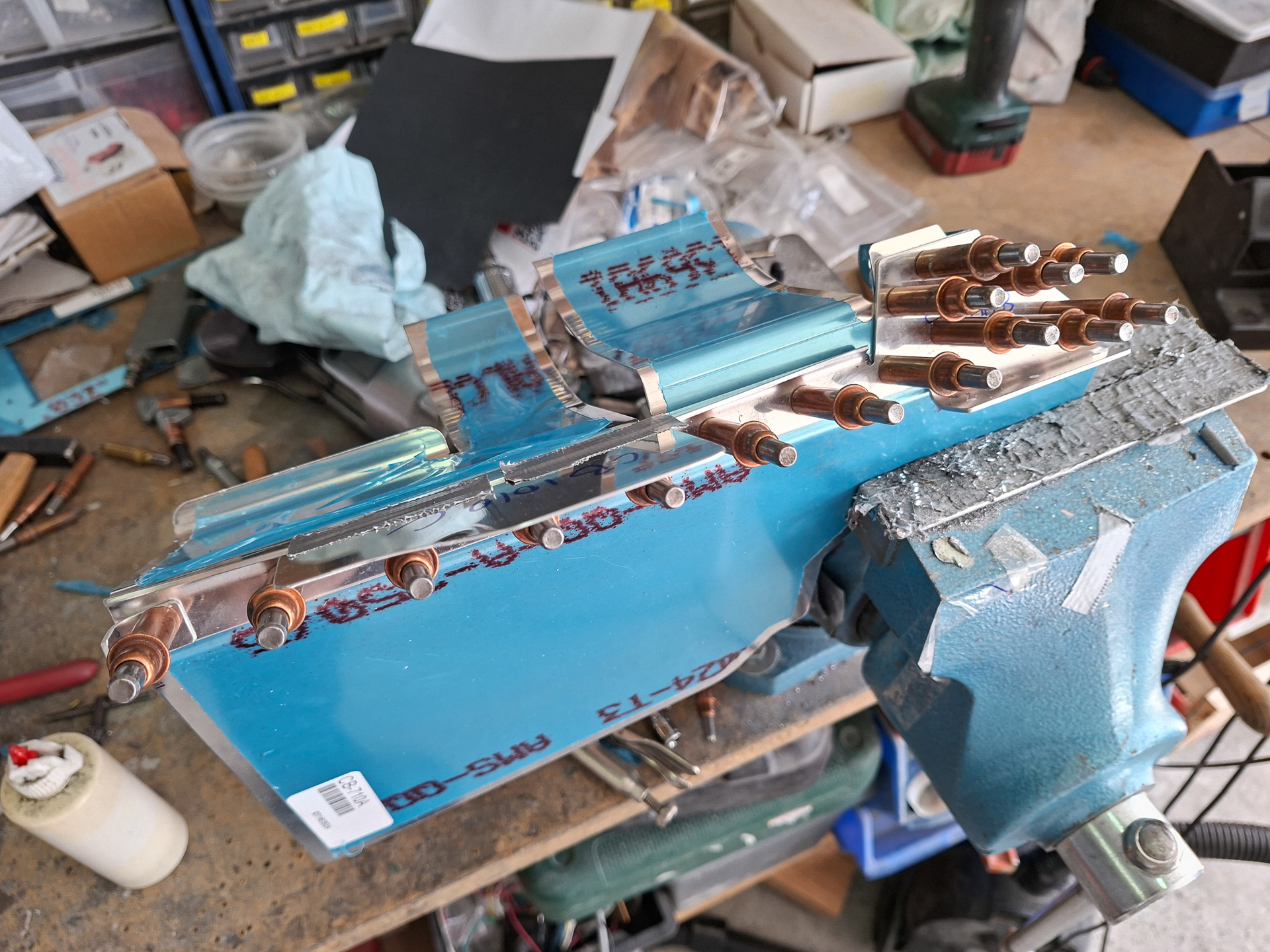
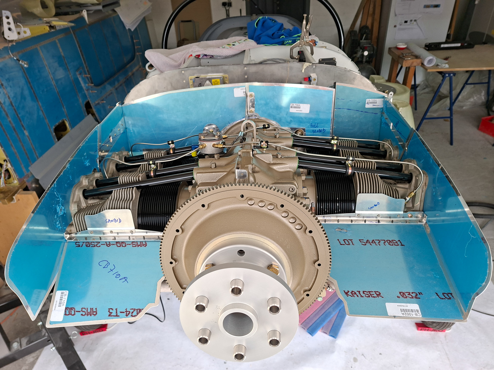
Today was a really big day on the building project. I remember how I have always checked on other builders websites and social media when they came at the point of working with the engine. It always seemed so far away for me at that point. Now, it's finally that day where my own engine work is starting and I can't tell you how excited and jacked up I am about this. After a lot of elaboration and a failed search for a used engine, I decided to buy a brand new Superior XP IO-360-A1AD2 engine. It's 180hp and fuel injected with classic magneto's. The engine was ordered at PMM Wingservice in Herentals and they will also assemble and test run it. The advantage of having it assembled and installed before it's being test run is that time up to the first flight is not critical. As the engine has not run yet, there will be no risk of corrosion if it stands still for too long. The engine will be test run only few weeks before the actual first flight. The disadvantage off course is that the engine will have to come off again prior to flight. It took about a year for the engine to arrive and today was the planned day that it would be assembled at PMM. I was very lucky that they allowed me to be present during the assembly work so I really could witness how the engine came together.
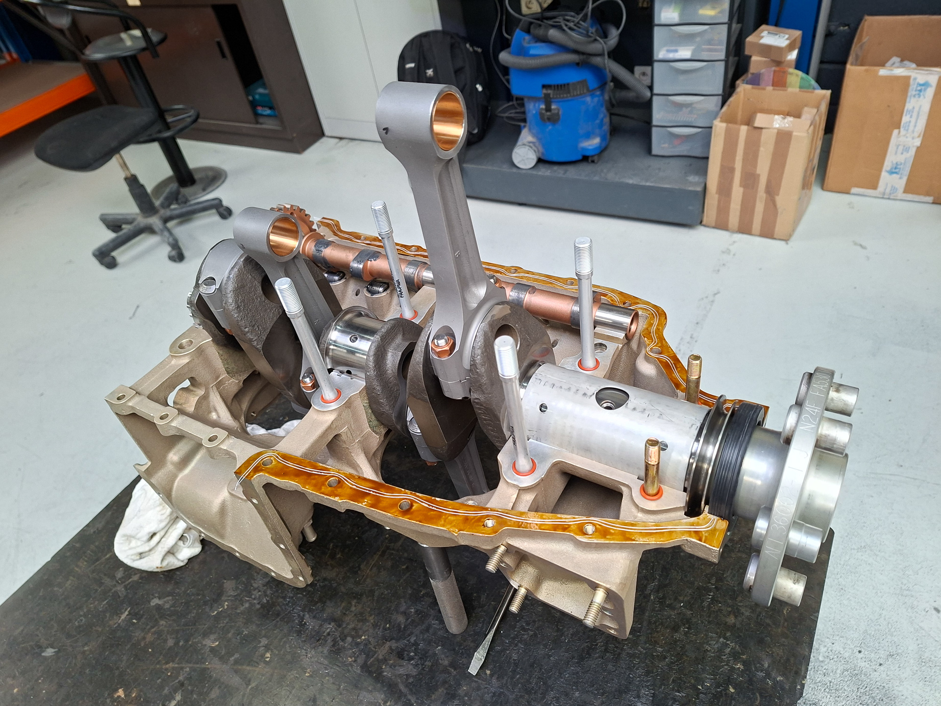
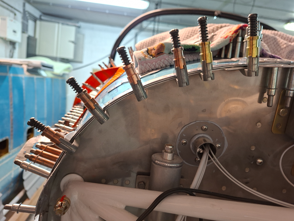
Here is an image at the very beginning with the engine case in halves.
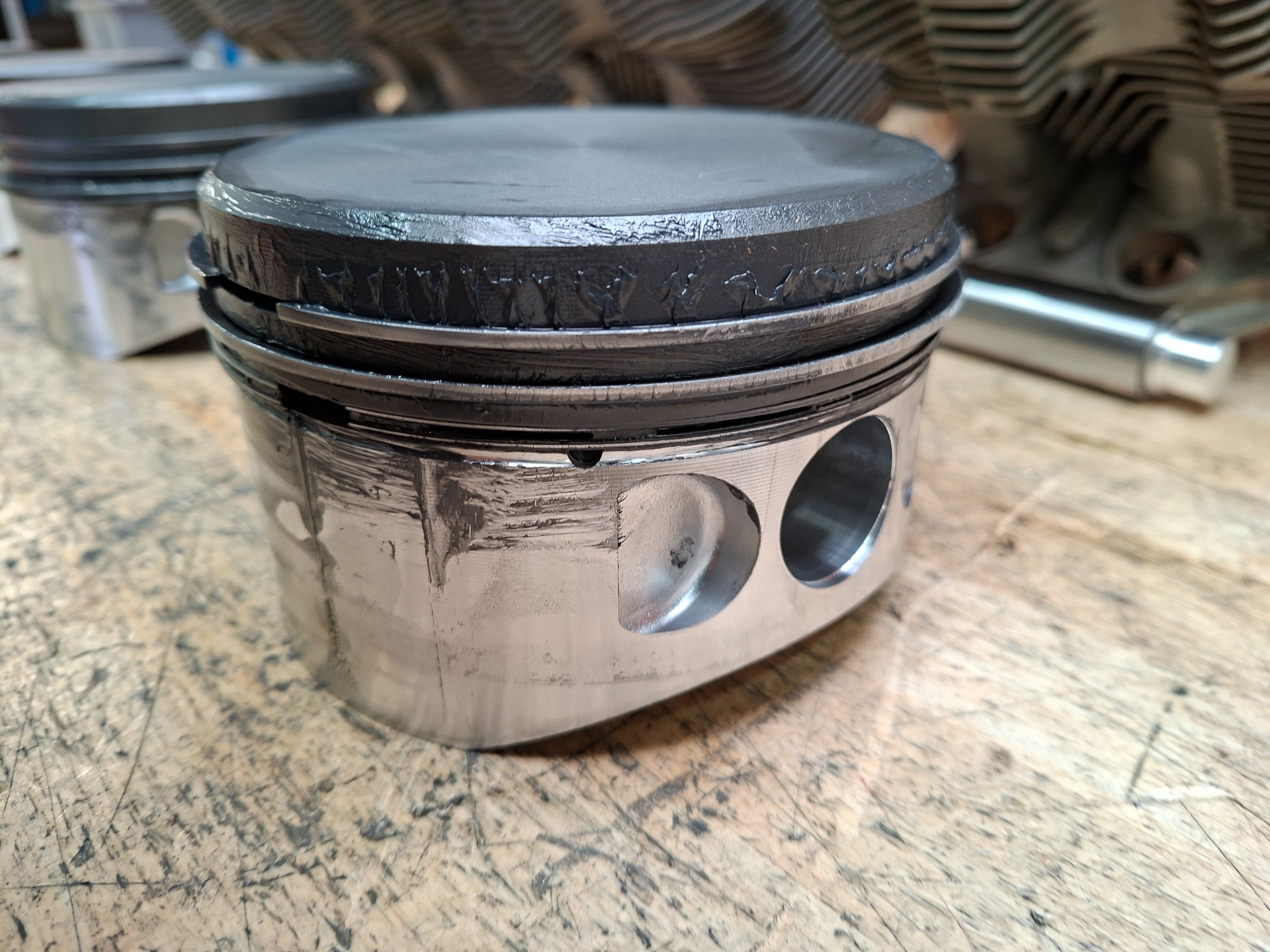
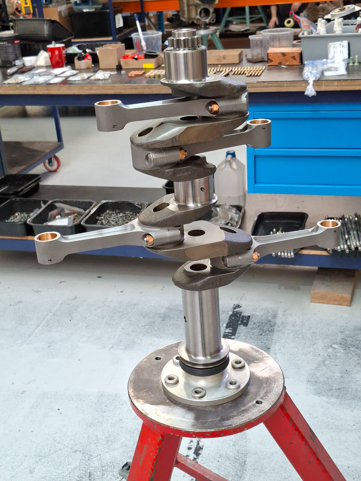
The crankshaft pusher arms that push the piston heads up and down and some pistons and cylinders.
This is how a cylinder head looks like from close by. A pin slides through the bottom side to attach the crankshaft push arm. The rings on the sides of the piston is what seals the compression chamber. The main reason for running-in the engine is because these rings need to "set" themselves to the cylinder walls. This is done by running the engine for some hours at 80% power at straight and level flight with good cooling. Failing to do so might lead to oil consumption which is hard to get out once it's there.
Here 's a picture of a cylinder head.
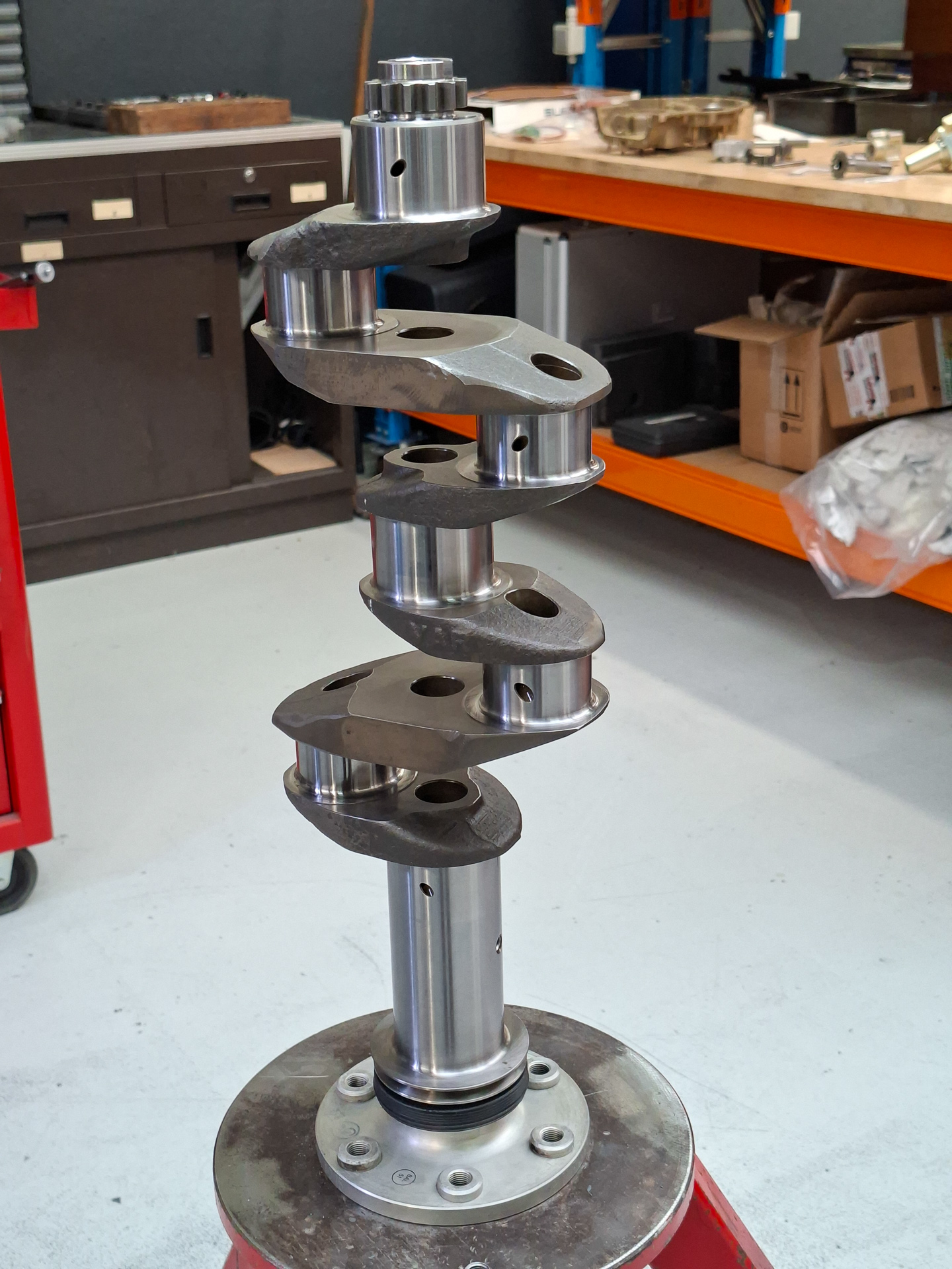
The crankshaft gets placed on a stand with the prop hub down.
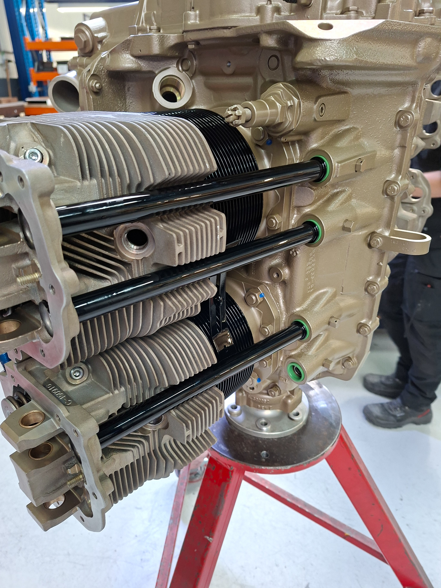
Then the pushers for the cylinders are installed on the crankshaft. You can clearly see here that cylinder 1 and 3 will be at top center while 2 and 4 will be at the down position.
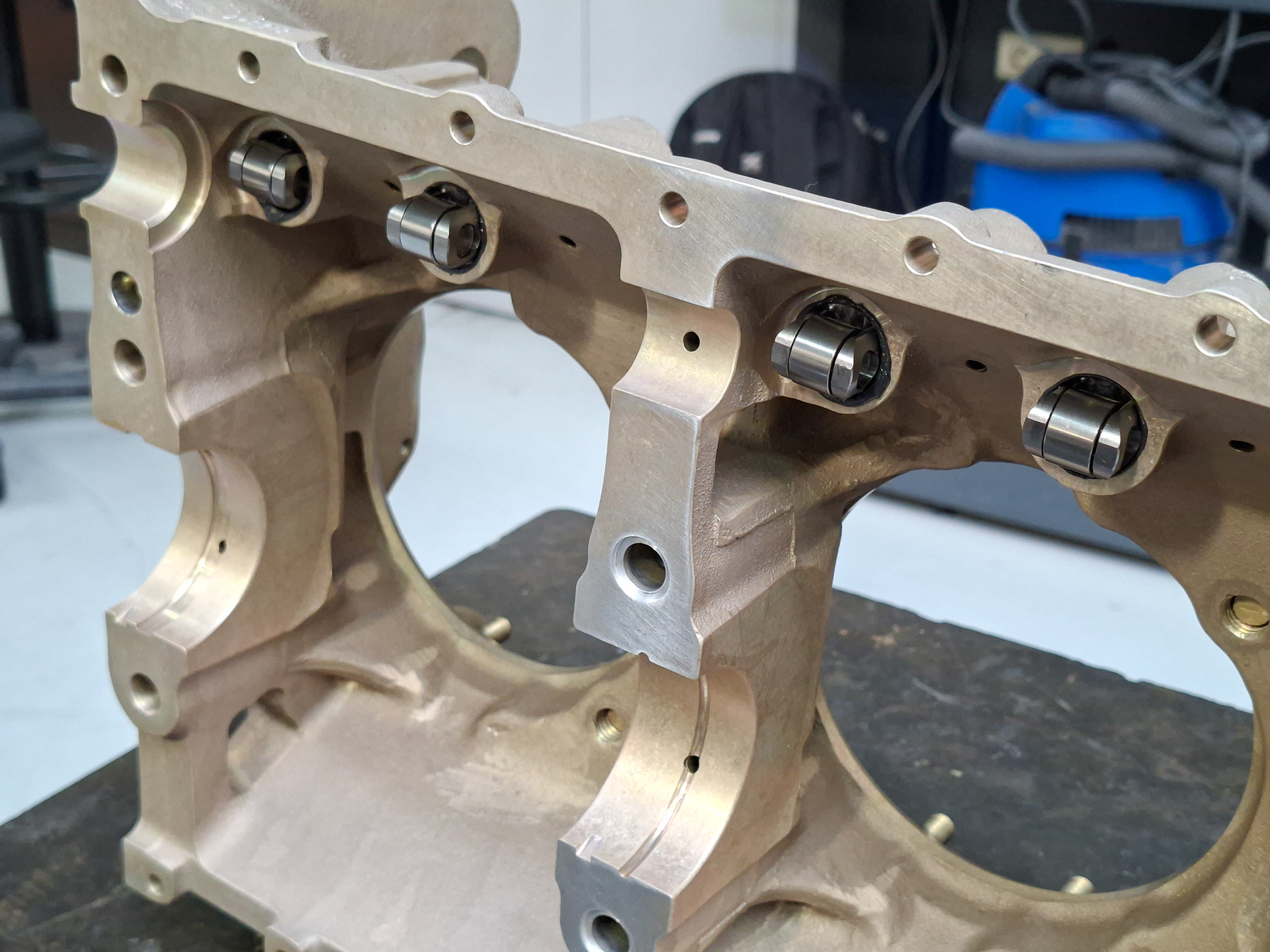
Next they install the roller tappets in the engine case. This is a unique system with Superior engines and a great improvement compared to classic Lycoming engines.
The 4 rollers you can see here in the top of the image are the connections that run on the camshaft. With classic engines, the pushrods that operate the cylinder valves are in direct contact with the camshaft. As these are not rounded, there is wear and grinding between the pushrod and the camshaft lob. With roller tappets, the pushrods "roll" over de camshaft lob which causes much less wear and possible corrosion points.
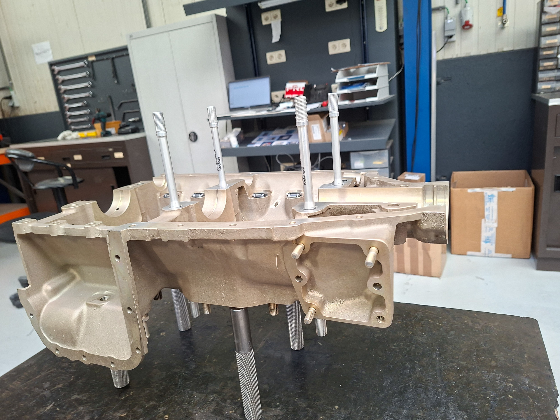
Next, the through-bolts are installed. As the name reveals, these are bolts that run through the engine case and are squeeze the case together. Small detail I learned is that when you loosen one of these bolt on one cylinder, you need to re-torque both sides when fastening again.
Then the crankshaft and camshaft are lubricated and installed in the case. A sealant is applied on the sides and also 2 nylon wires which help preventing oil leaking.
Then the engine case is closed.
By the way... in the movie you can see Patrick Van Dooren and his son Kobe. Patrick is owner of PMM WIngservice and a local legend in the engine construction and maintenance world in Western Europe. It's an honor having a guy like that working on your engine.
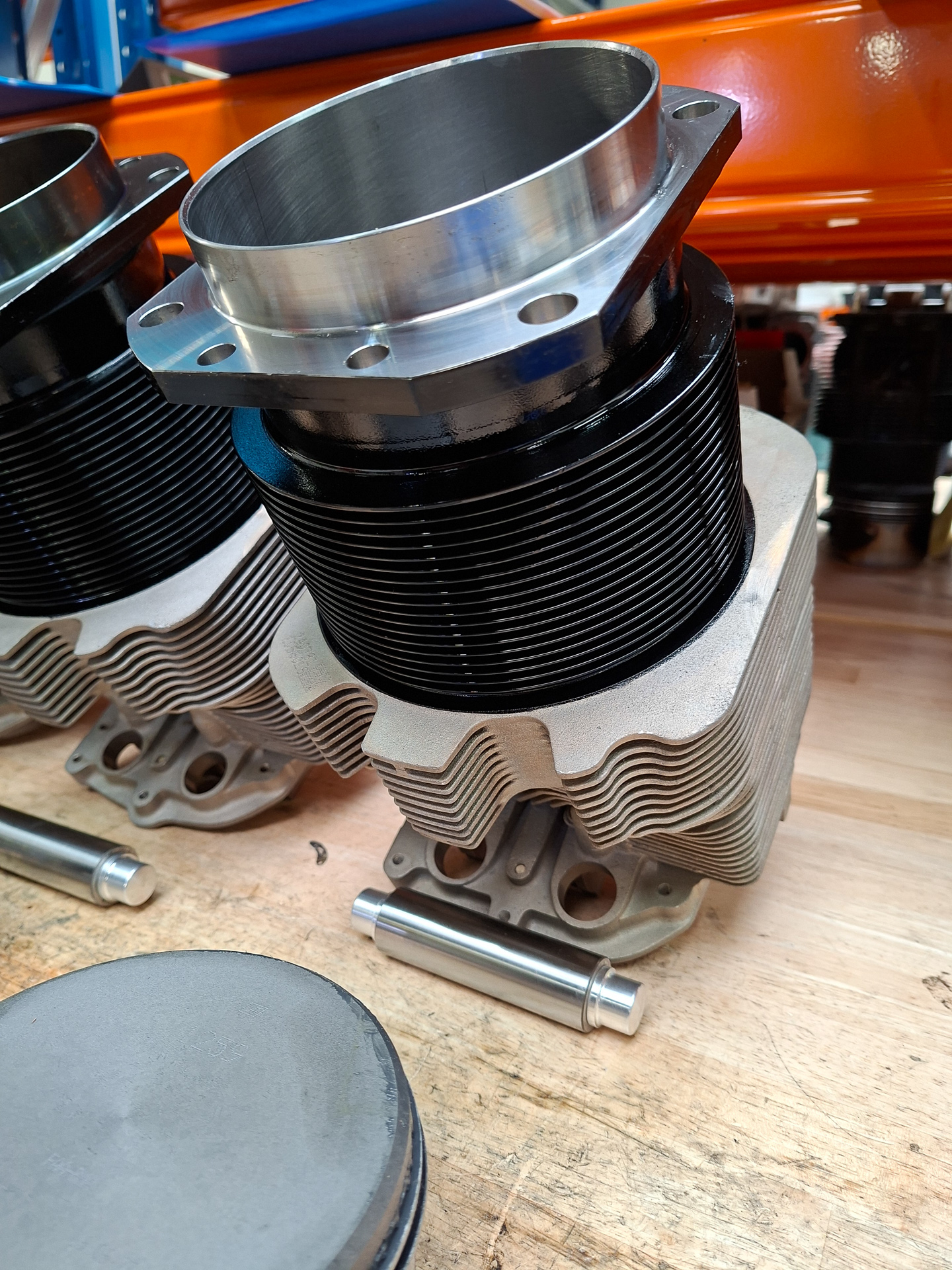
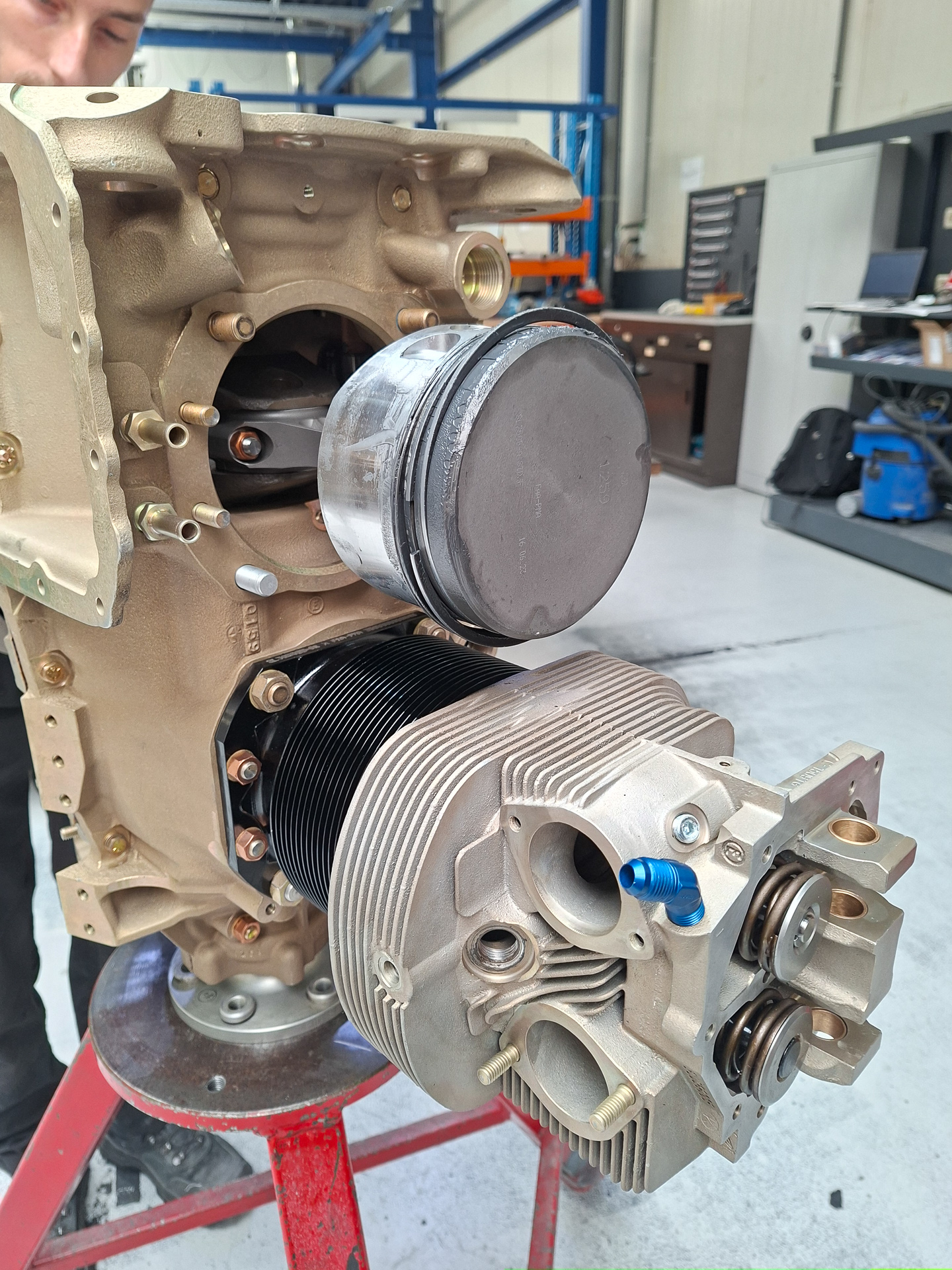
the cylinders are installed by sliding the cylinder cases over the pistons while the side rings are clamped inwards.
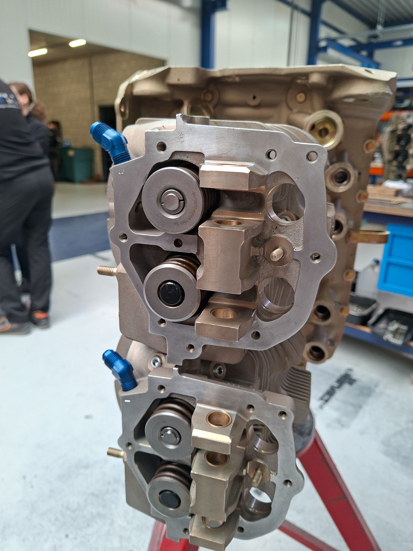
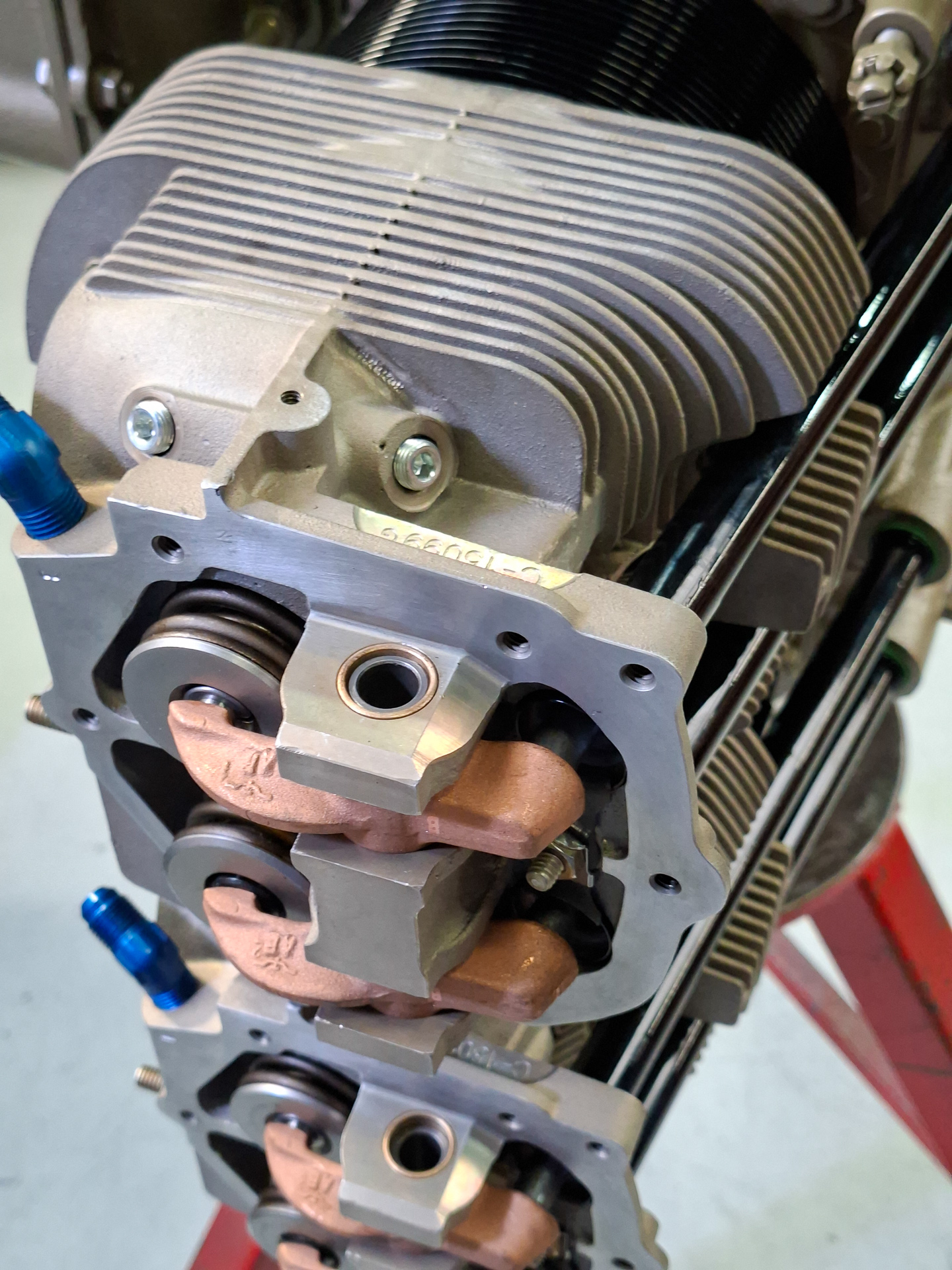
The image below shows the top side of the cylinders. You can see the 2 round valve heads.
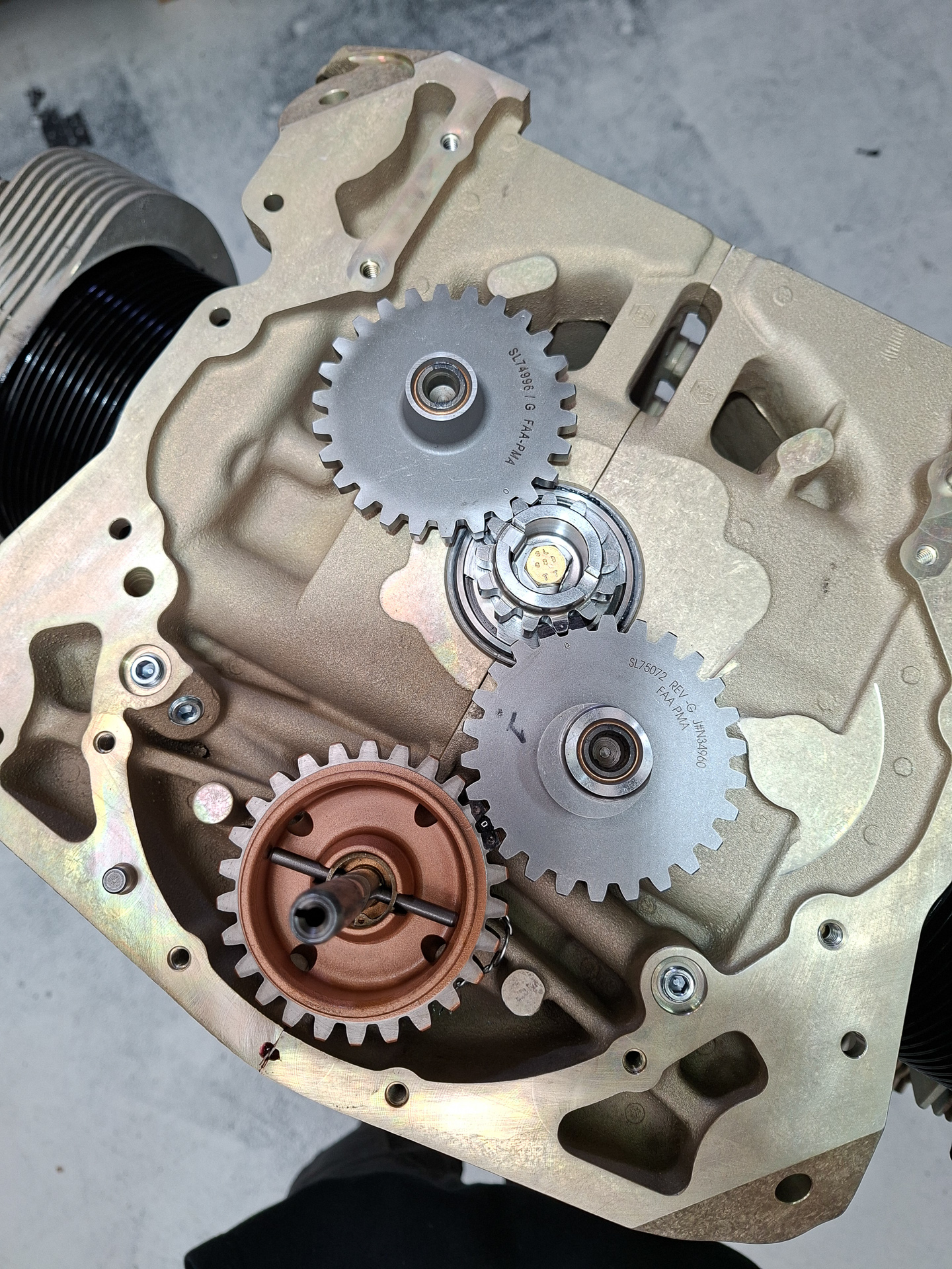
In the back, you find the gear box that drives various peripherals like the magneto's, suction pump, engine pump and the camshaft. The small wheel in the center is the main crankshaft drive. The 2 other gray gears are driving the magneto's. One of the magneto gears connects to the camshaft gear which logically is 4 times the size of the crankshaft gear as it takes 4 rotations of the crankshaft for one full rotation of the camshaft.
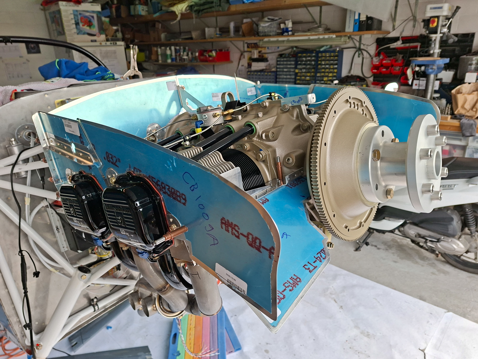
Then the cold air induction sump is installed. The top shows the oil sump with 2 oil drain points. The middle shows the 4 air intake pipes that come behind the location where the TBI (throttle body injector) will be attached.
This more or less concluded day 1. The engine covers and the engine case will now be painted and assembly work will continue tomorrow.
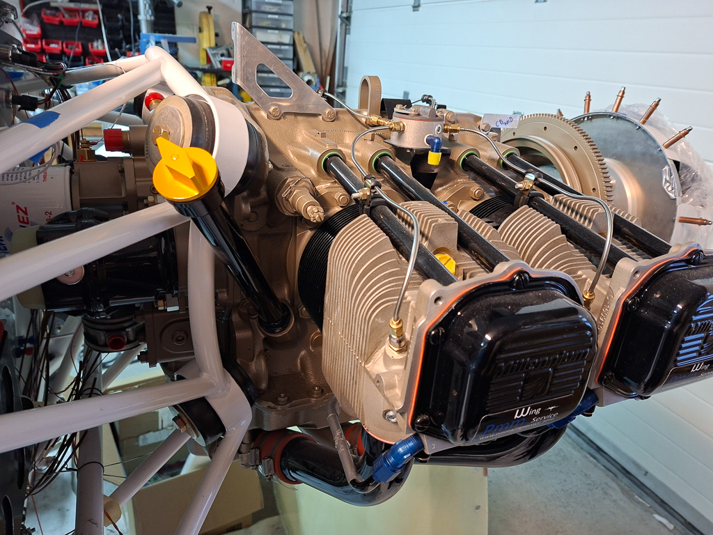
24/04/2025 - Engine assembly day at PMM (part 2) - 6h
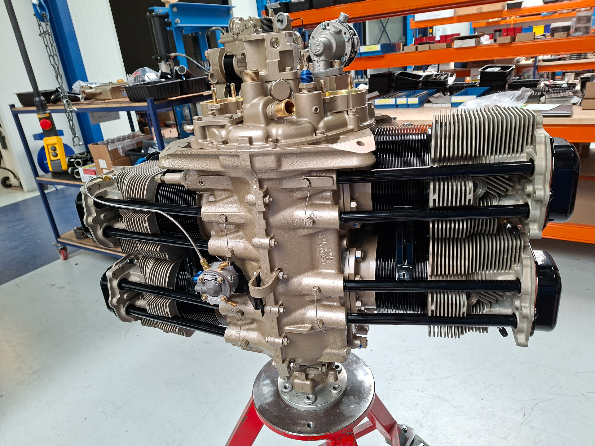
The engine and covers are now painted in Continental engine scheme having a gold colored engine block and black shiny covers and pipes. The look is absolutely beautiful.
Now it's back to assembling parts. Next step is the installation of the parallel valve pushrods. Between the actual pushrods and the roller tappets (see previous day article), some small push style devices are inserted. They fit right behind each roller tappet.
Here you can see them inserted in the engine case.
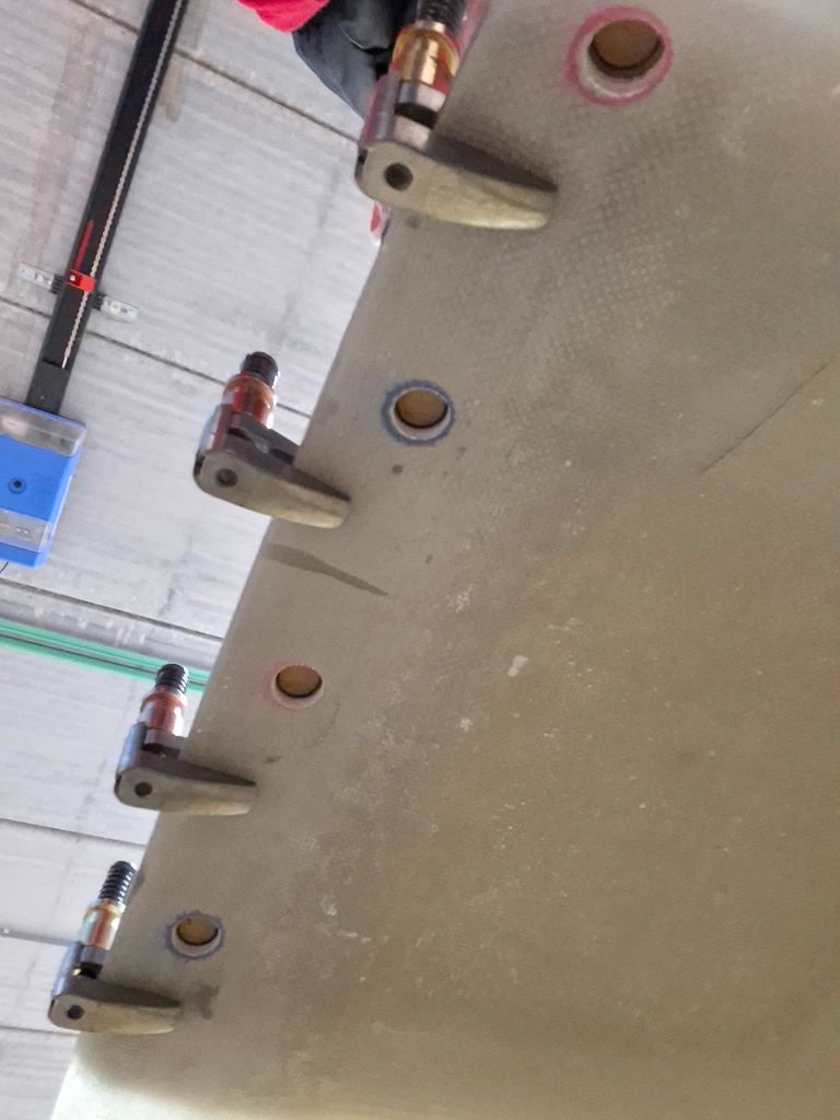
Then the rods and rovers are installed.
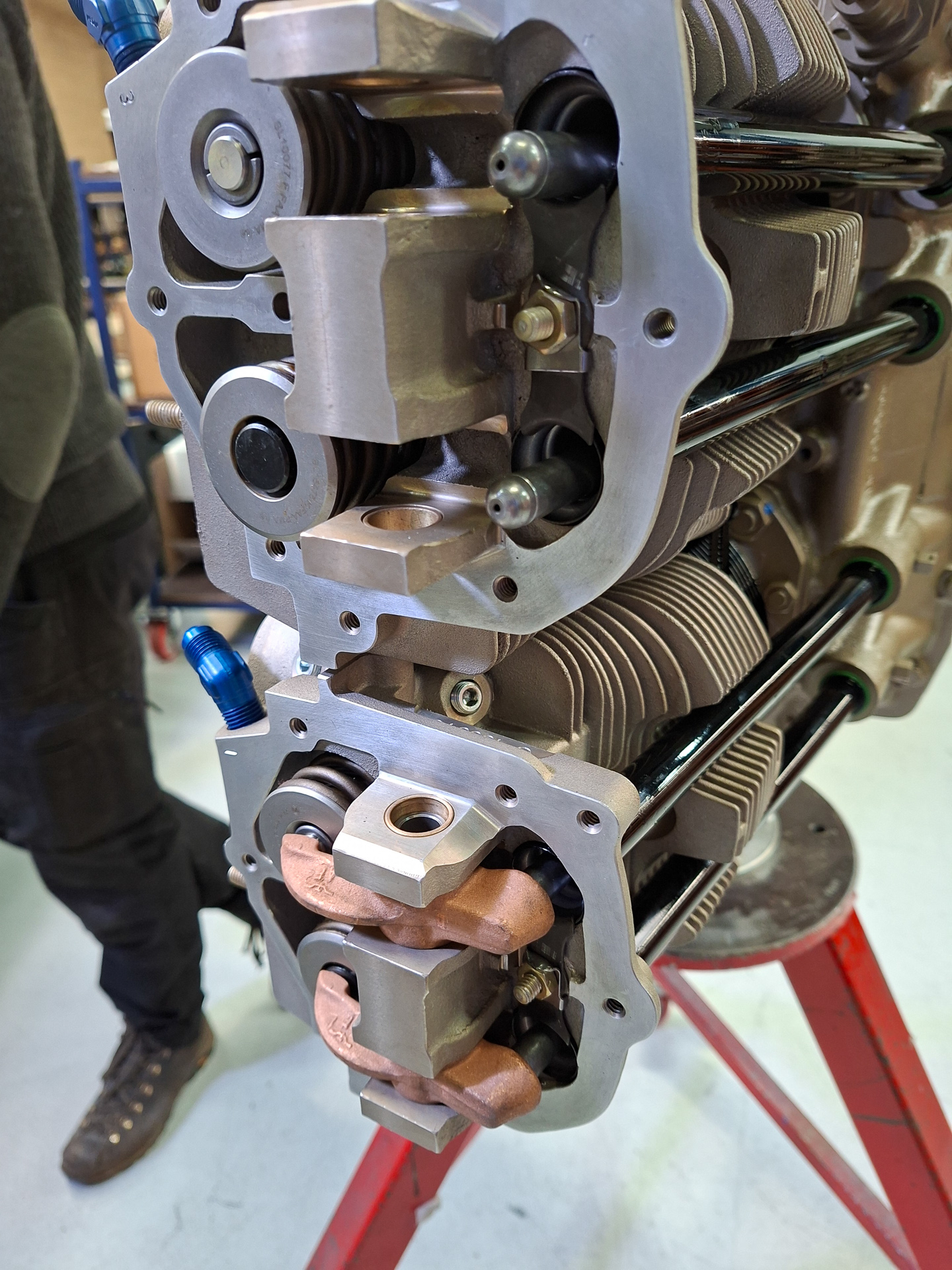
In the image below you can see the heads of the pushrods sticking out and the lower cylinder already has the little pink colored hammers inserted. These hammers transfer the pushing movement from the rods on the actual cylinder valves.
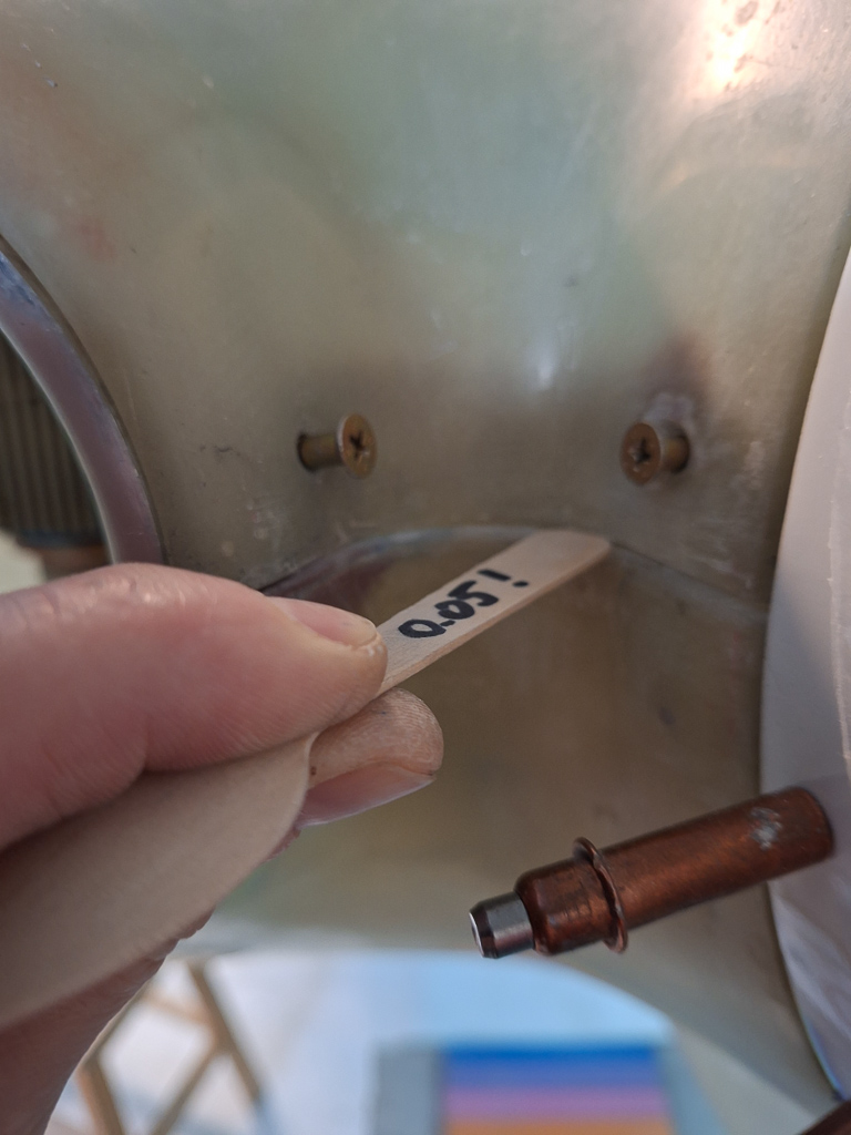
There is a special tool from lycoming that is used to test the spacing between the hammer and the valve head. This distance has to be within a defined range. Too little and you get problems with the opening and closing of the valves. Too wide points to wear on the pushrods or the camshaft lobs.
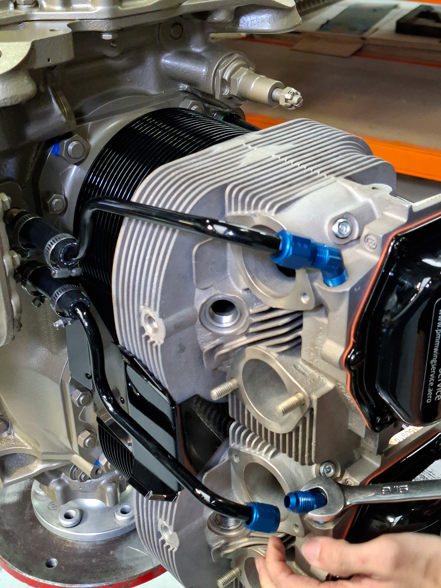
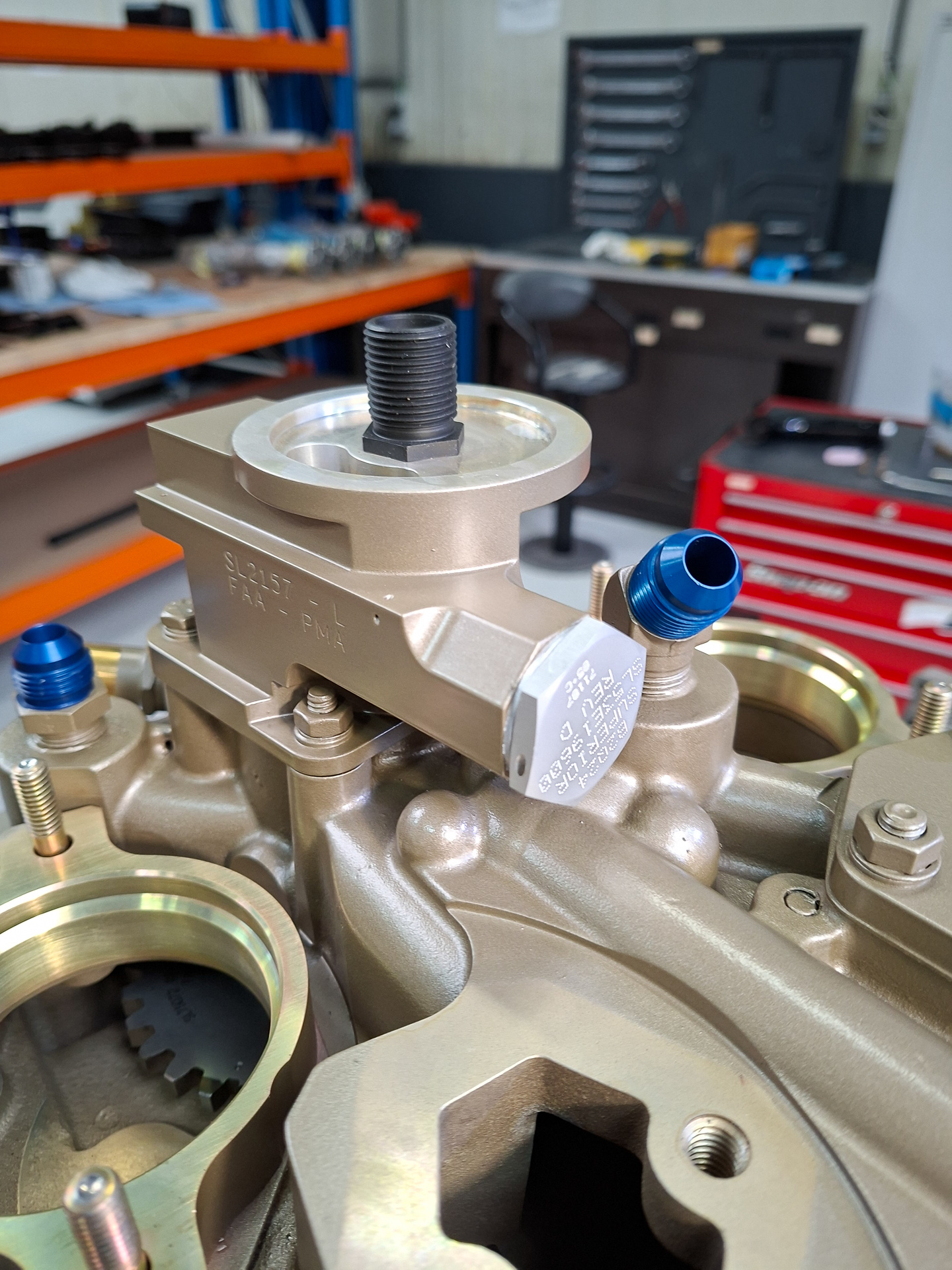
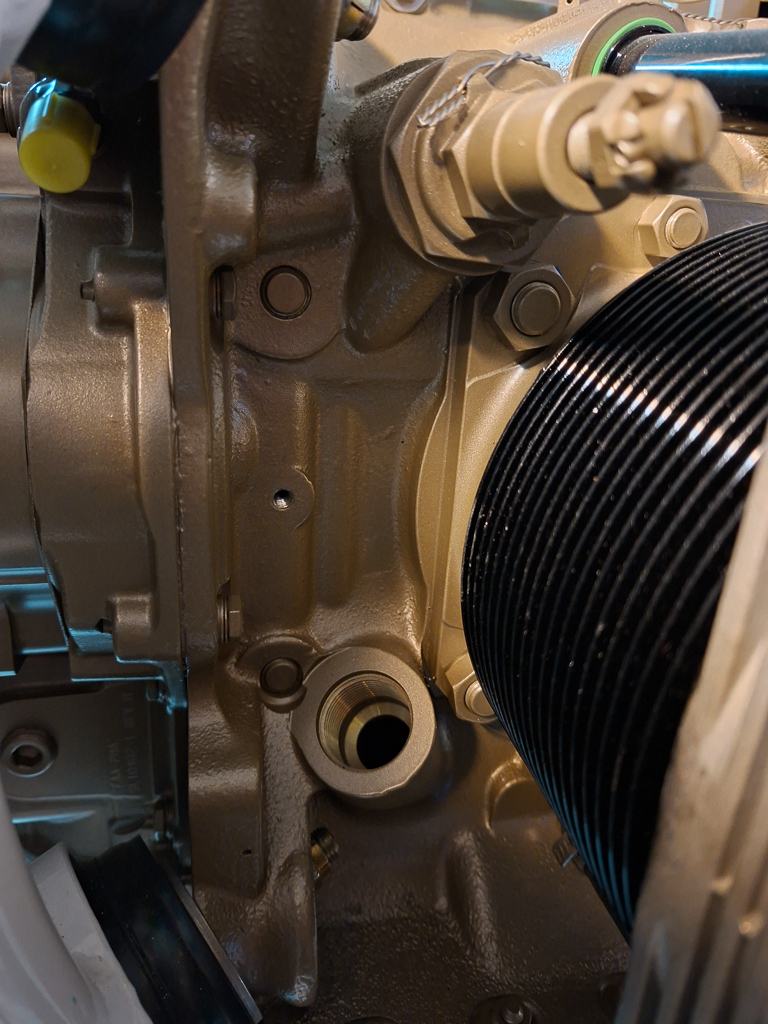
In the image below, the oil return line is installed on the blue AN fitting. In the top center of the image, you can see the oil pressure regulation valve.
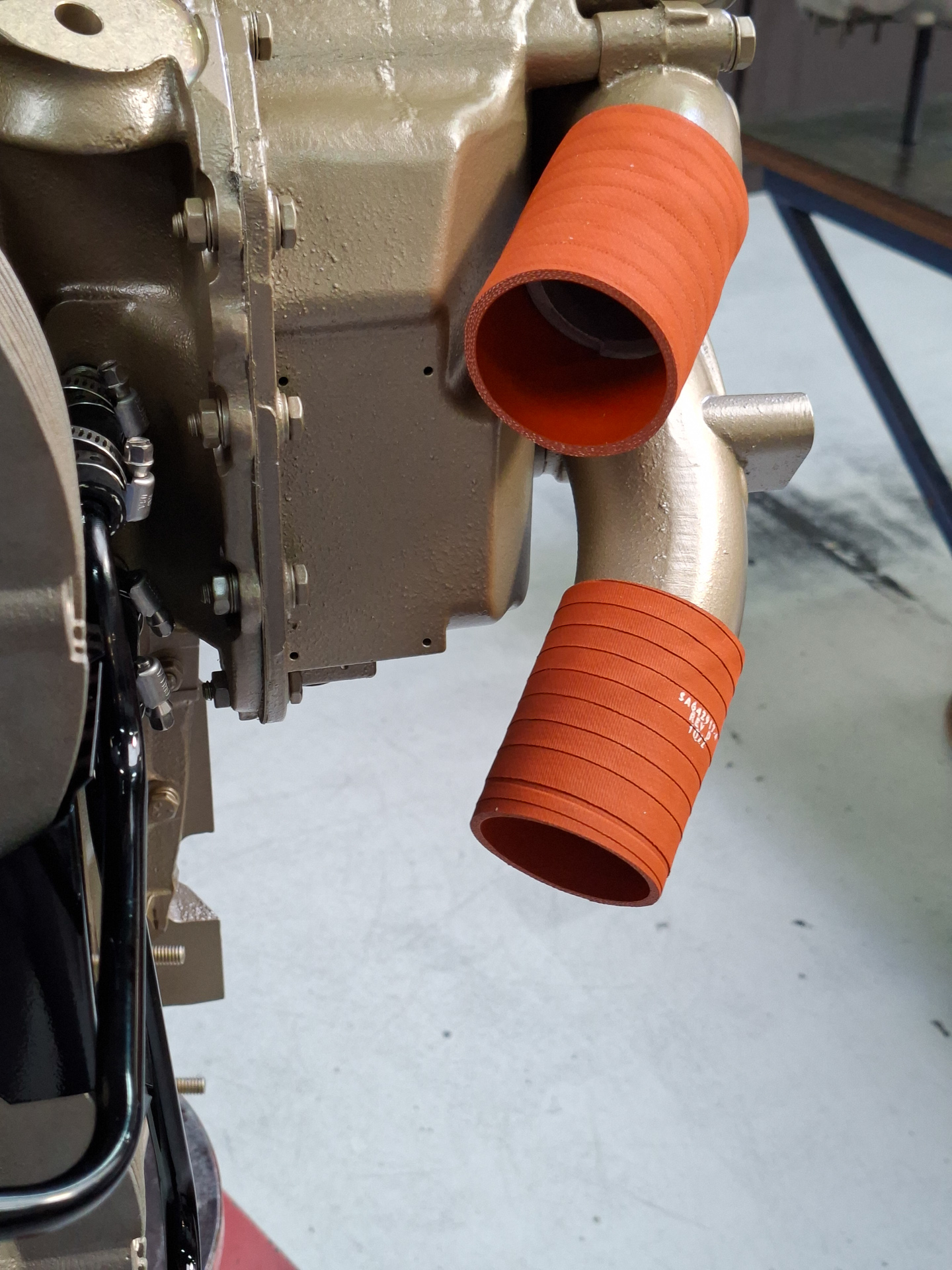
Some muffs are installed on the cold air induction air intake exists before the tubing is installed that connect the sump to the cylinder air intake.
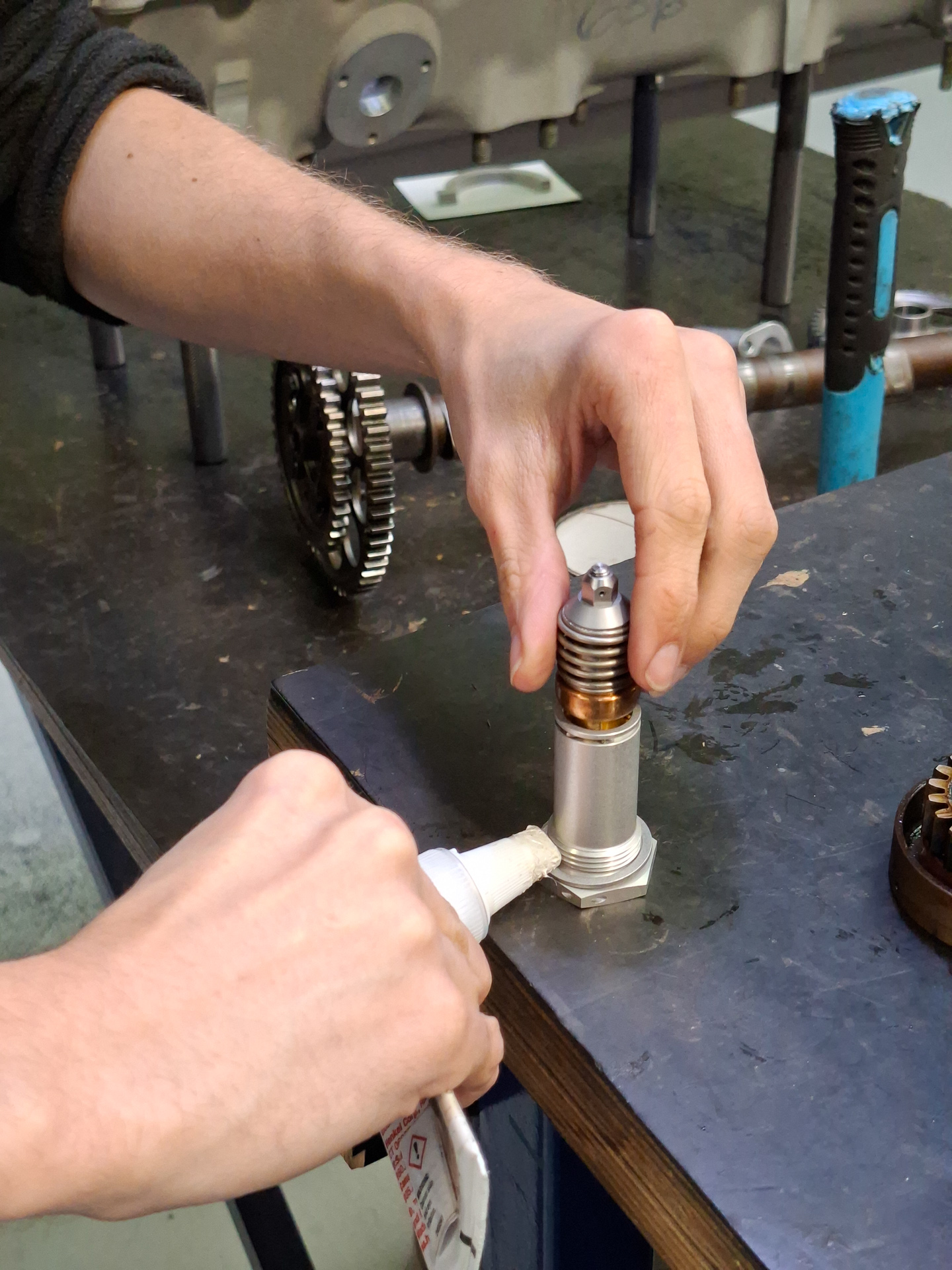
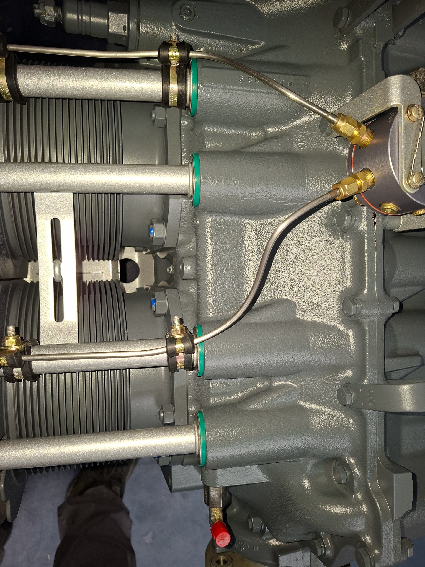
The image below shows the installation of the oil thermal valve. This mechanism is installed close to the air filter and regulates the amount of oil that is sent to the oil cooler.
You can see it installed here underneath the connection point of the oil filter.
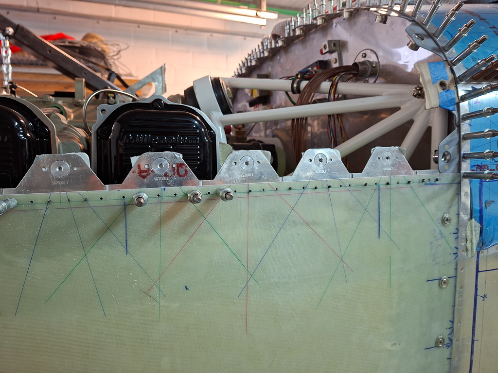
For the fuel line between the injector spider and the TBI, I had the option to go behind the cylinder nr 4 or in between 1 and 2. Patrick showed me the last option on another engine. Advantage of this is that it's a much shorter line. You can see the hole on the baffle plate between the cylinders here.
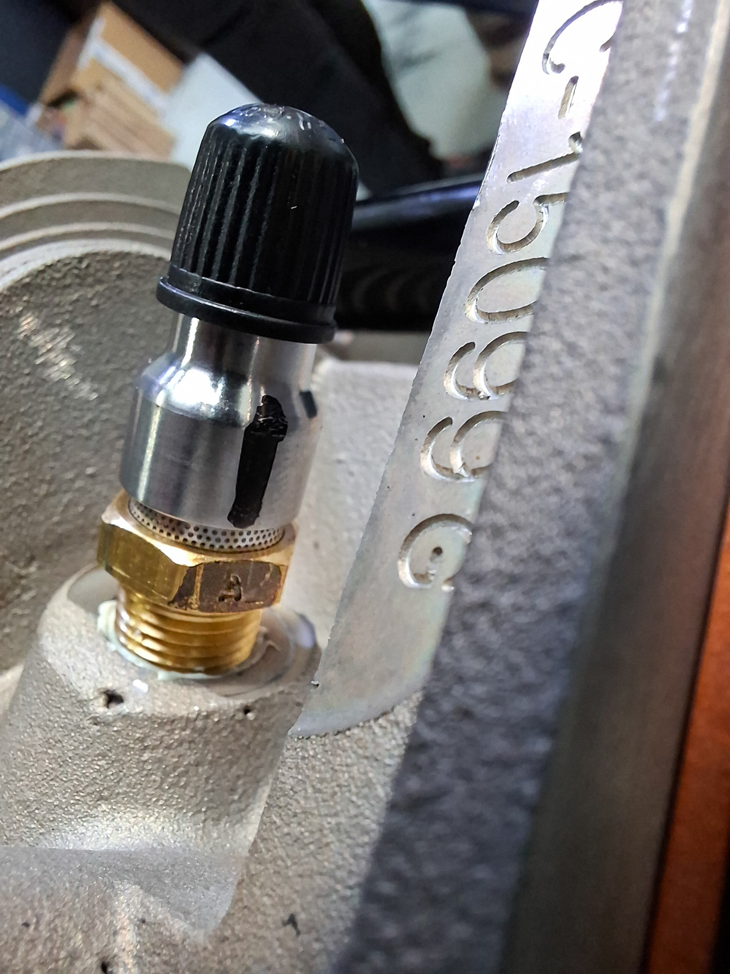
The fuel injectors themselves are installed on the cylinder head. This is the place where fuel gets sprayed in the cylinder by the injector body. Important detail here is that the little A marking on the injector has to be on the bottom side, otherwise it won't work.
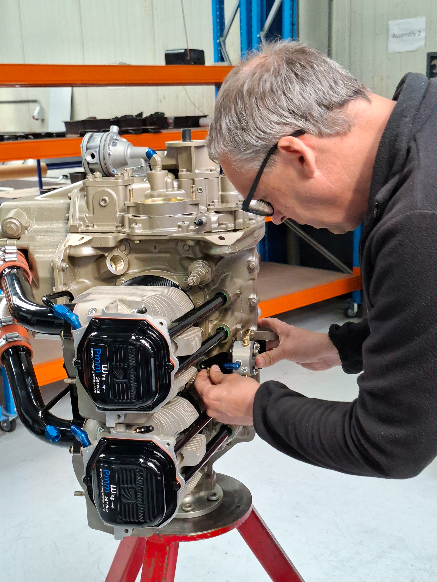
Here Patrick is installing the spider on the top of the engine. It's amazing how he just bends away on these fixed length pre-flared fine tubes and gets the job done within minutes. It would probably take me 3 days and 5 mess-ups to get one of those done. This guy is a true magician.
As I also opted for the in between cylinder pass through for the fuel line, they were so kind to take it back appart and make the holes in the inter cylinder baffle. A grommet will be installed here to protect the fuel line.
Then the fuel pump was installed and some fittings which they already installed like the oil restrictor fitting, the AN oil fittings. And that's as far as it got at this day.
There some minor remaining work to be done like the magneto's and couple more fuel injector tubes but it's close to completions.
Next week I can go and pick it up to bring it home.
05/05/2025 - Bringing the engine home from PMM - 4h
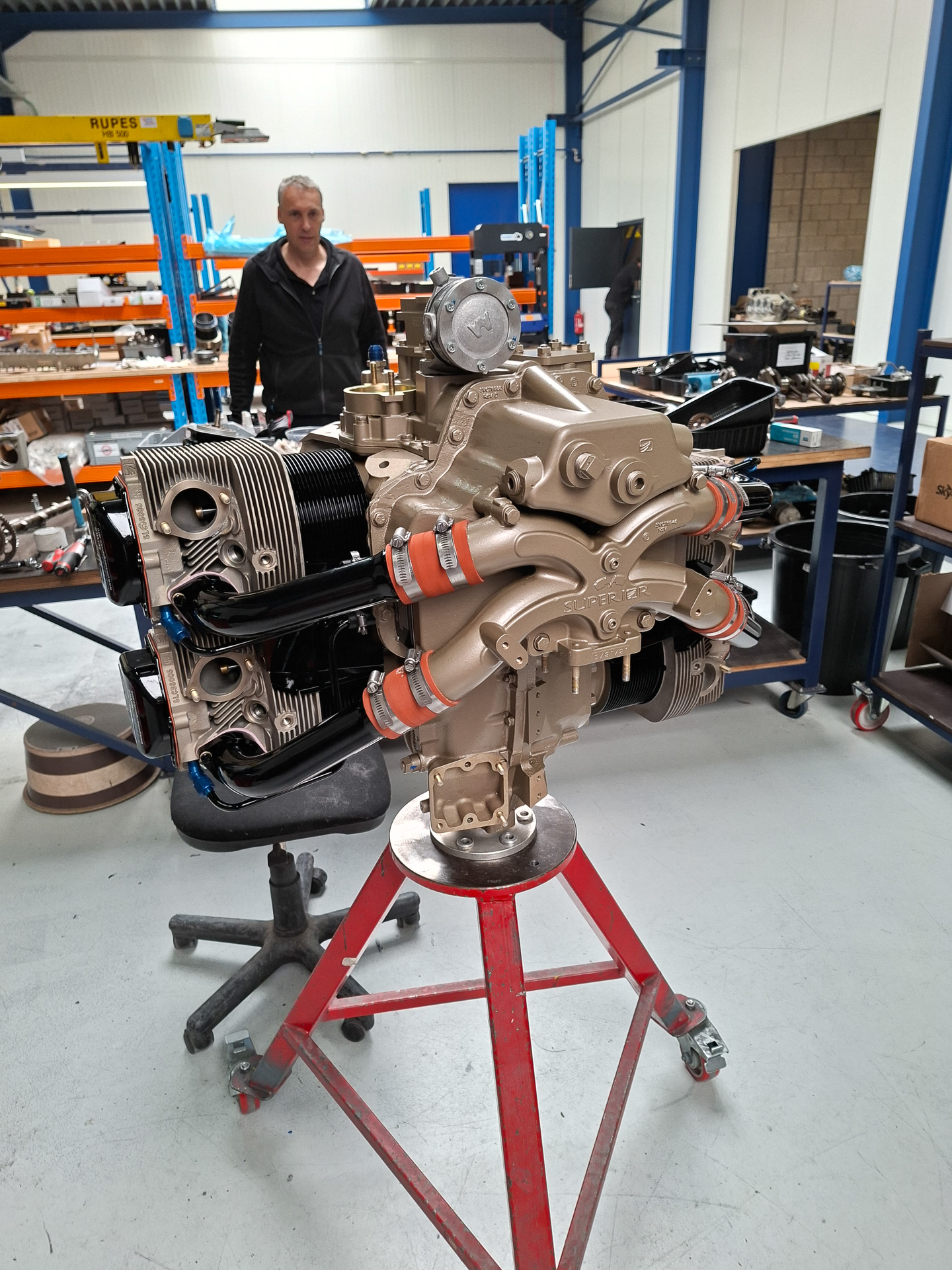
Big day I have long time been waiting for : my engine came home and is now in the workshop !
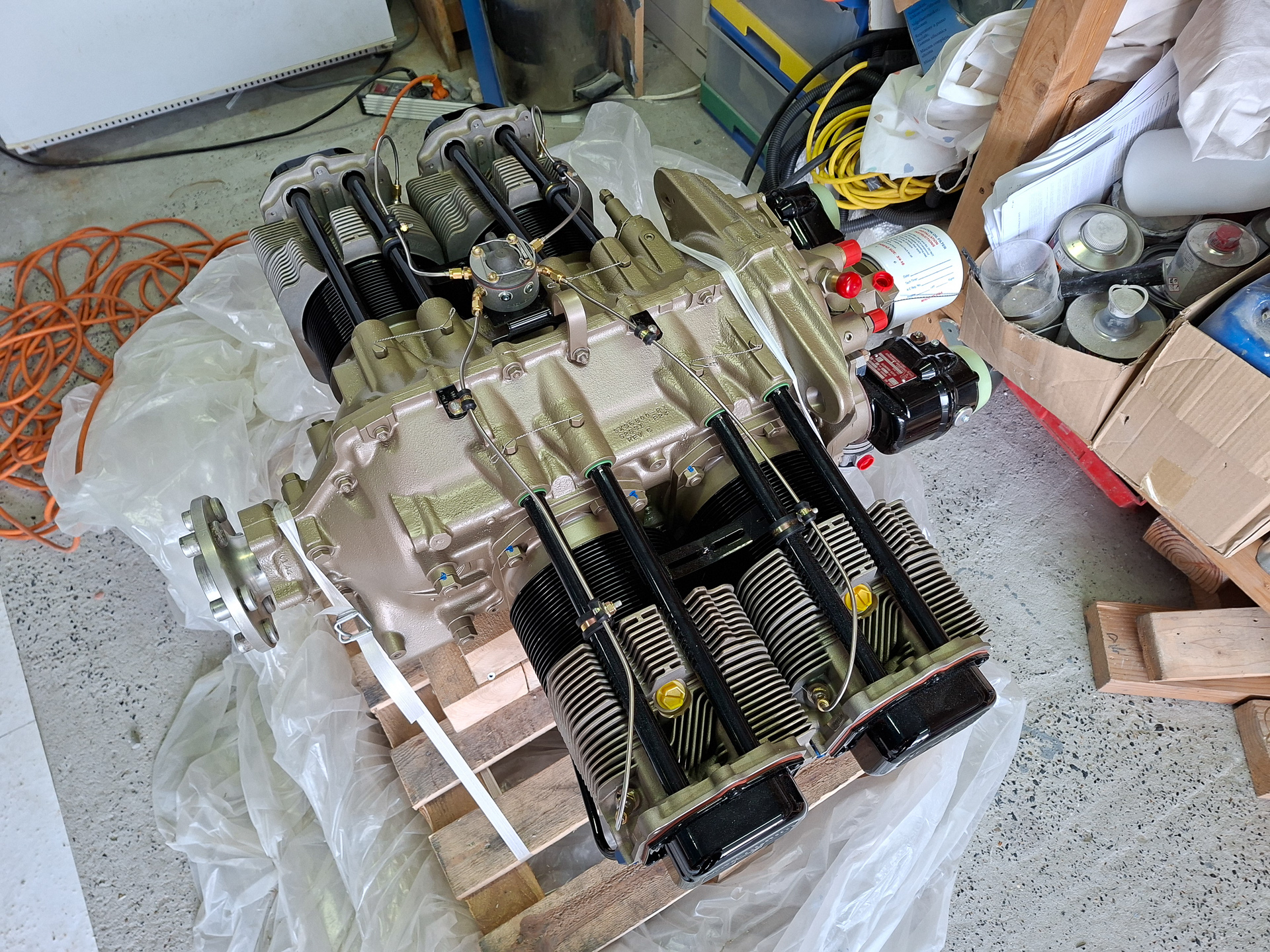
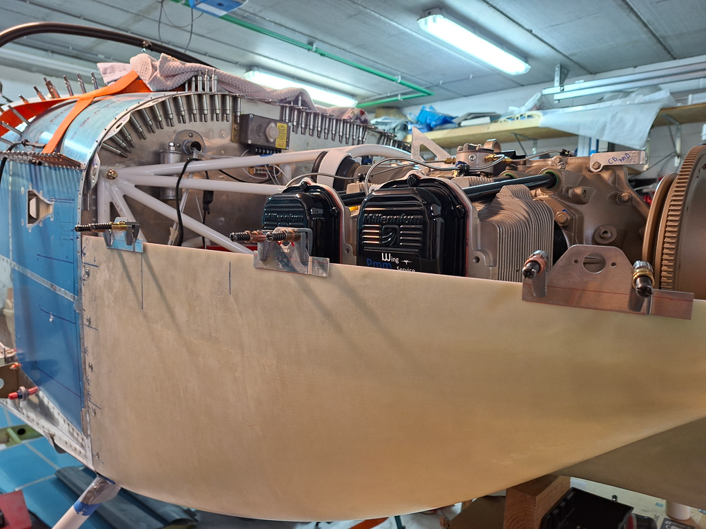
We used a Ford transporter to go and pick it up at PMM Wingservice. They had fixated the engine on a pallet supported by some wood blocks in the front and standing on the cold air induction sump in the bottom. Some straps around the case keep it on the pallet and stop it from moving. Moving it into the car was easy with a clark. We used straps to secure the pallet in the car so that it can't slide. At this point, nothing is attached to the bottom of the engine. No starter, no alternator, no throttle body and this is also the way it has to be brought back when it will go on the test bench.
After a 2 hour drive, we arrived at the workshop. Boy this thing is more heavy than I anticipated. We moved it by sliding on the ground and drove the car all the way into the garage.
The engine hoist slided underneath and we were able to lift the engine out of the car. The engine hoist has a V shaped base so you can't just put it on the ground and be done. We had to bring it down on the V shape base and then carry the pallet with 3 persons to the final location.
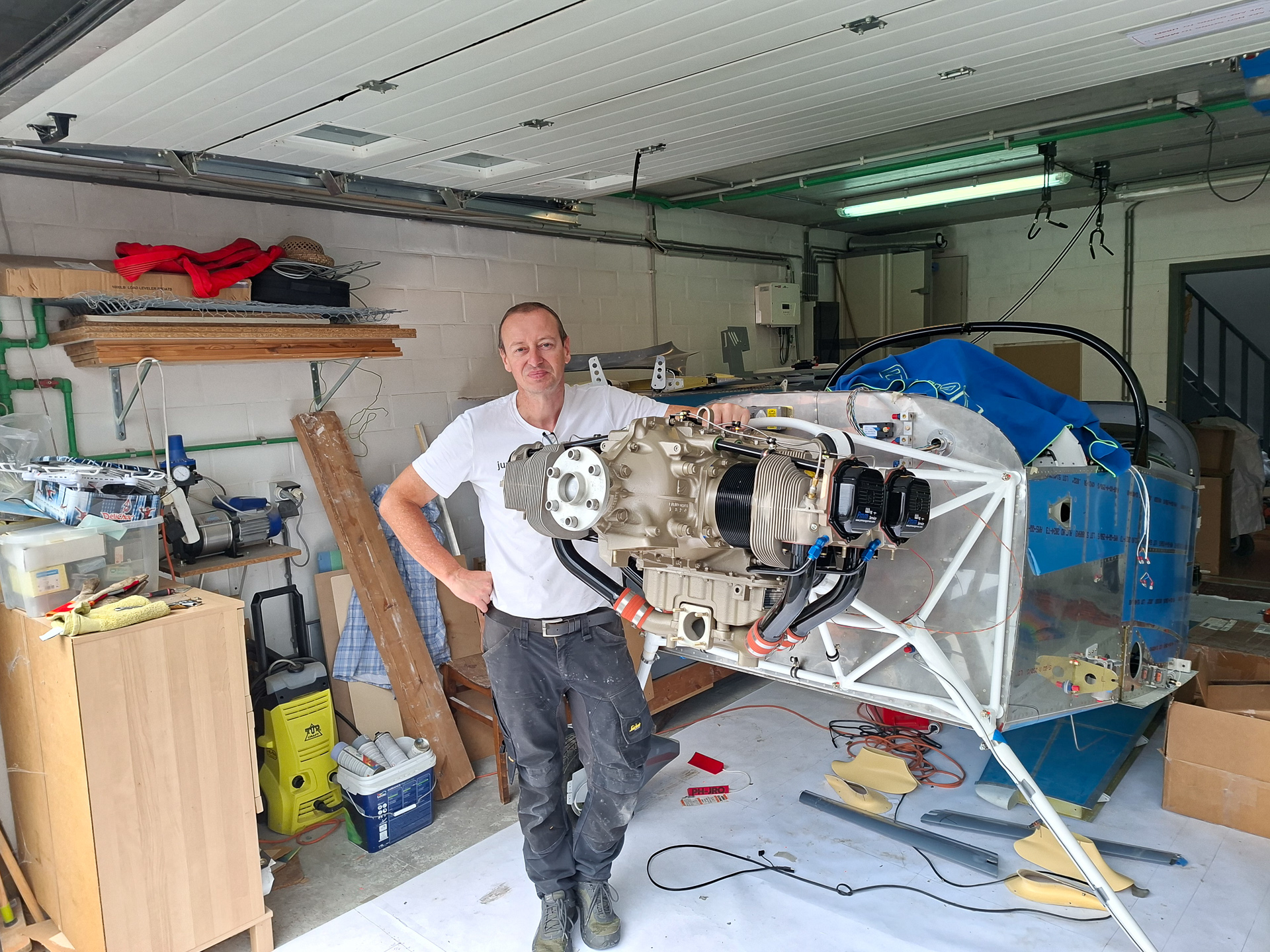
Here's Matthias, my son posing with the engine. In the initial pictures of my workshop, you can see him as a 5 year old toddler. That says a lot about how much time I have spent and how many years have lapsed since the beginning of this project. Sometimes I curse and wish the thing to hell, but I never regretted starting on this journey. The only way from here is up, literally...
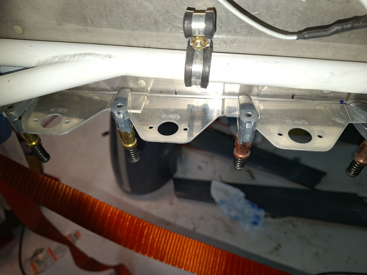
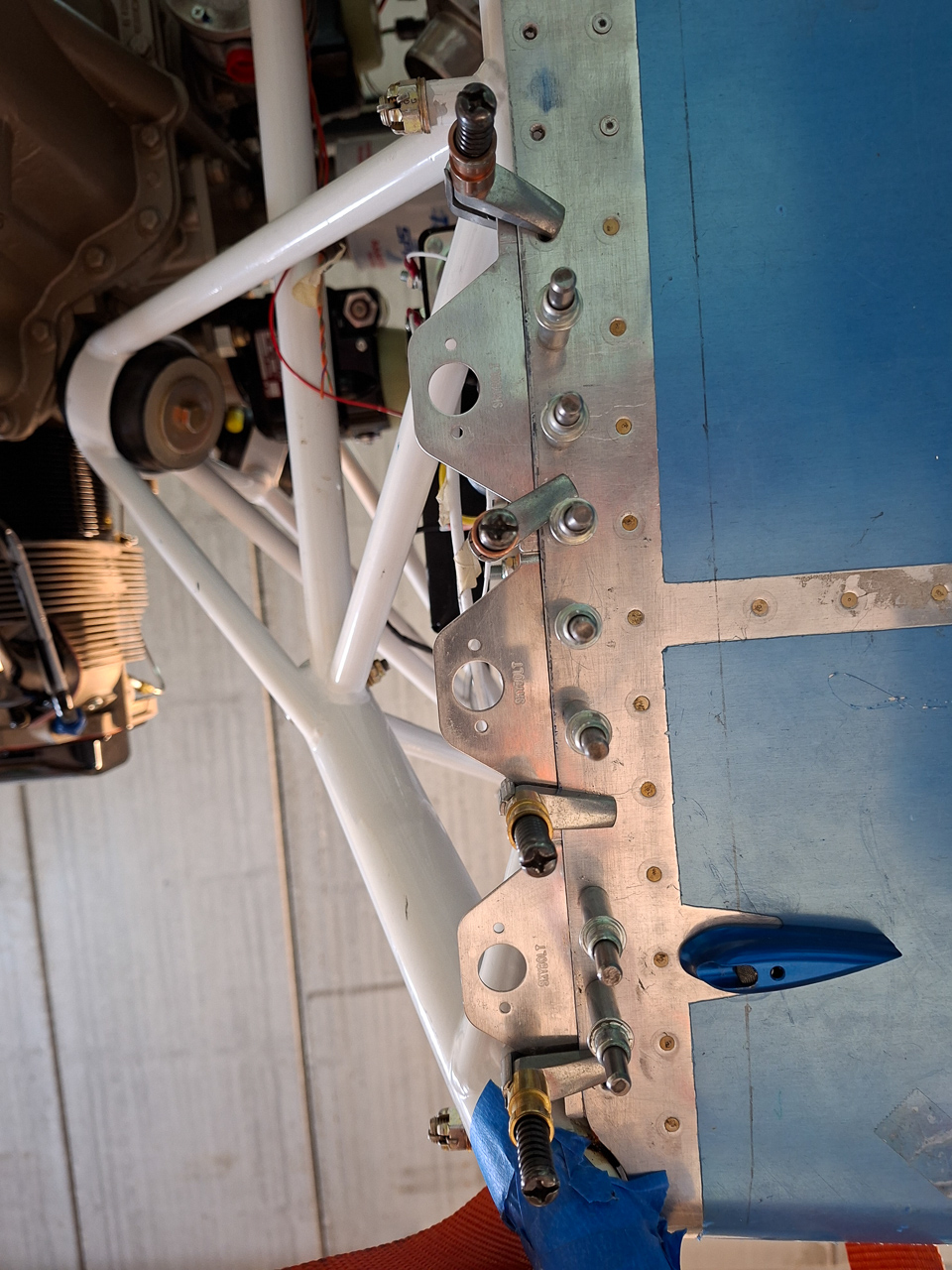
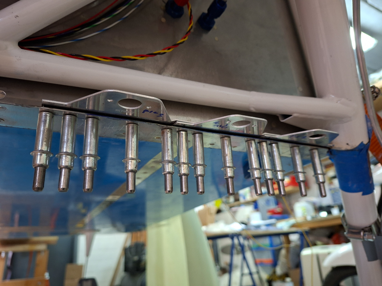
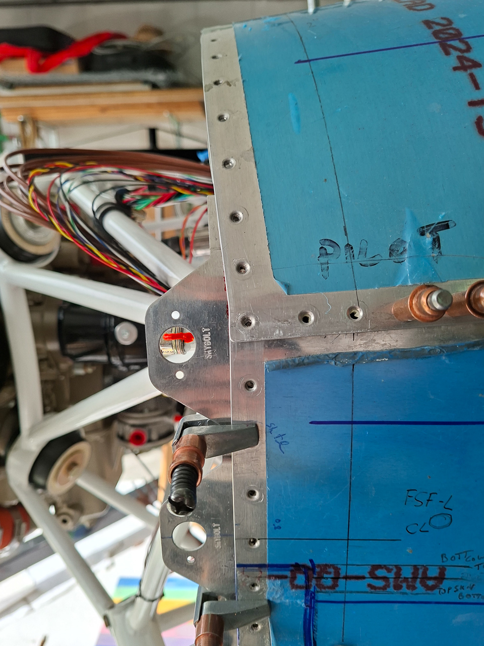
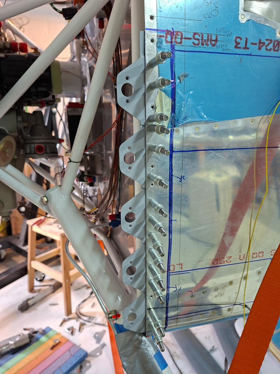
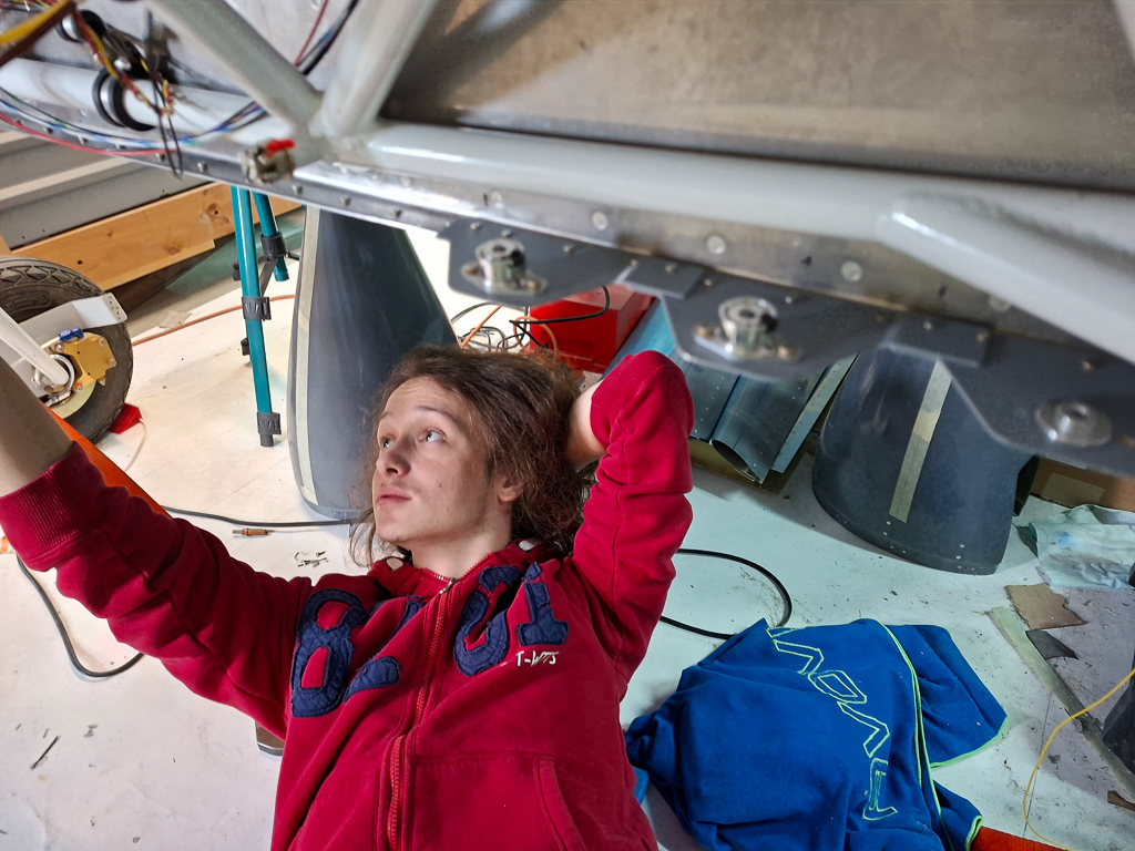
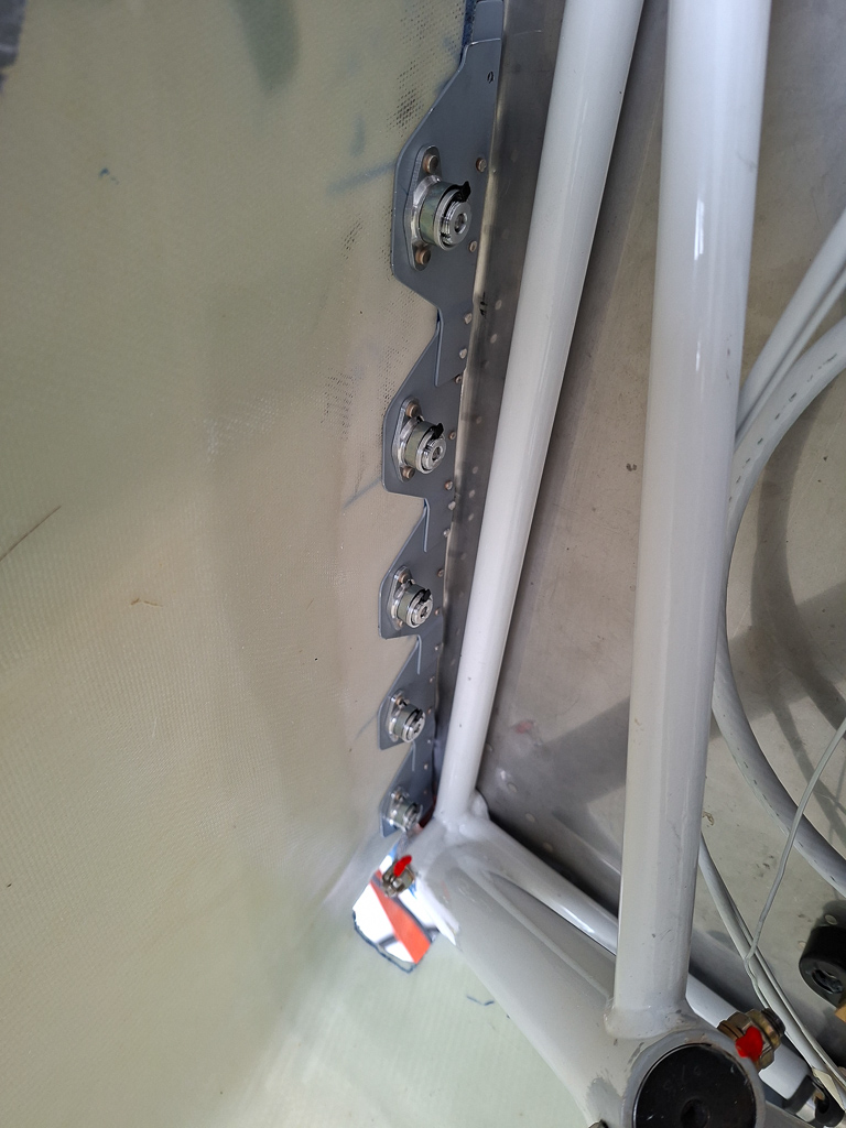
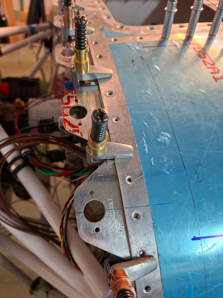
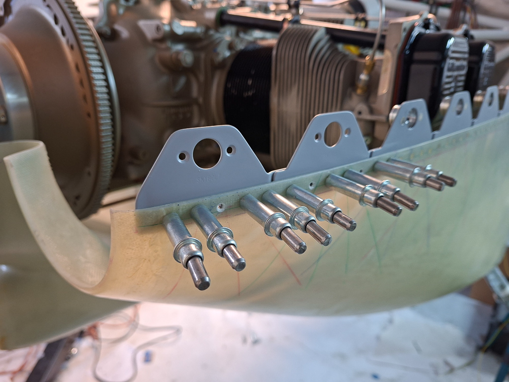
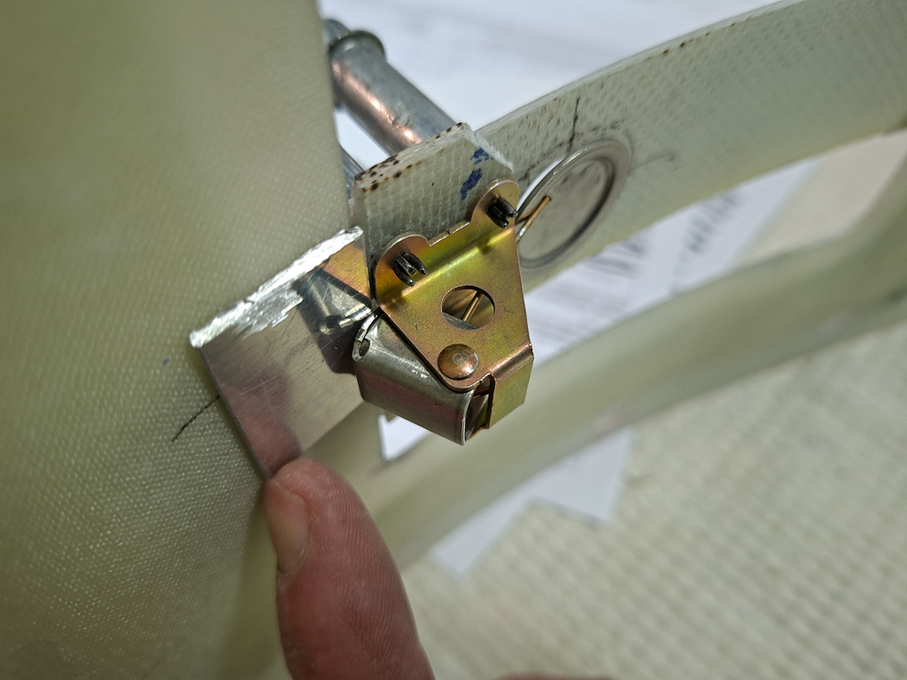
28/06/25 - Nutplates on firewall recess - 3h
Hanging the engine comes closer and closer. I started investigating what other things I was missing on the firewall. Once the engine hangs, access to the firewall becomes extremely difficult. You can off course always drill from the inside but getting a rivet gun in there is difficult.
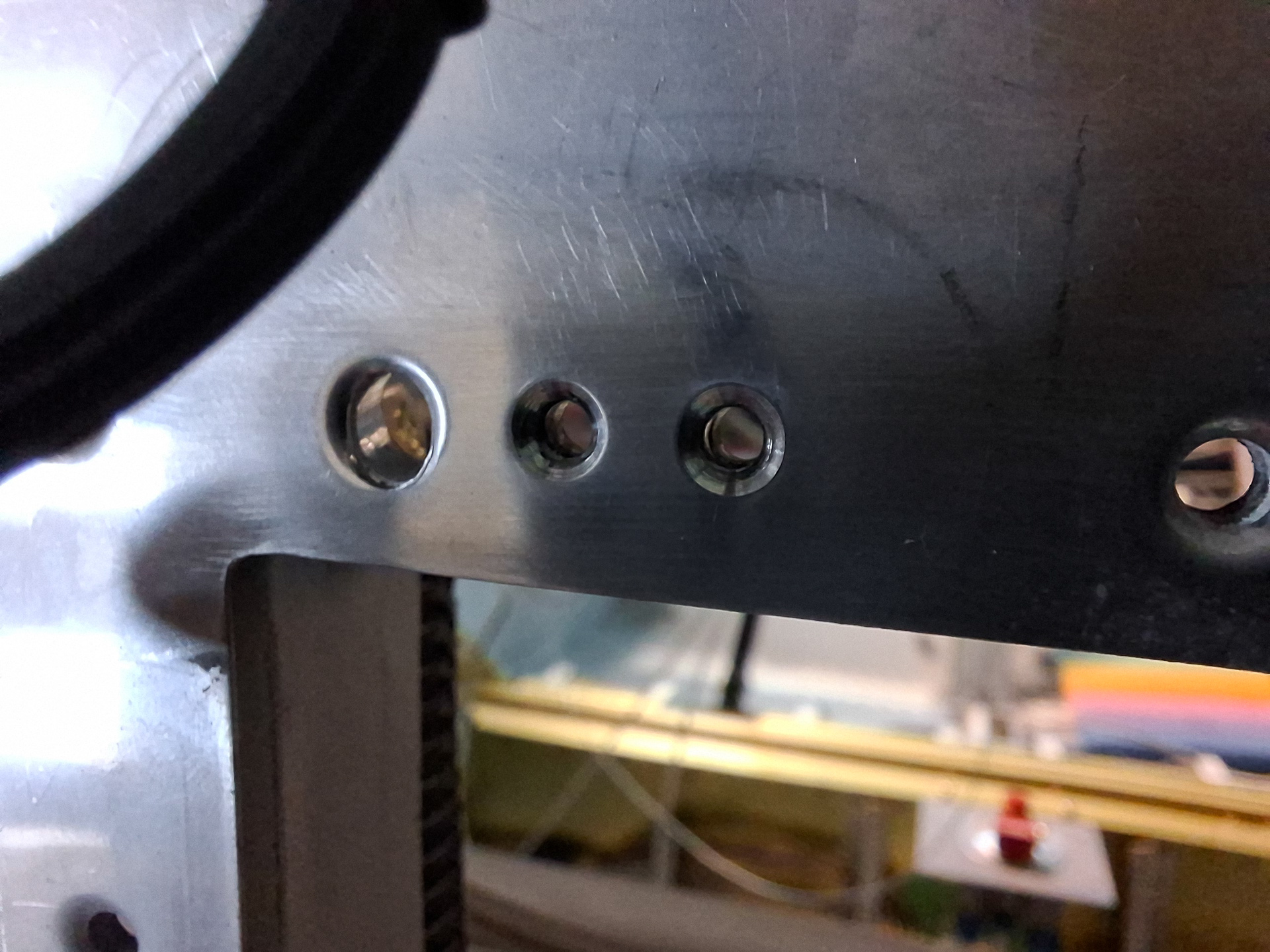
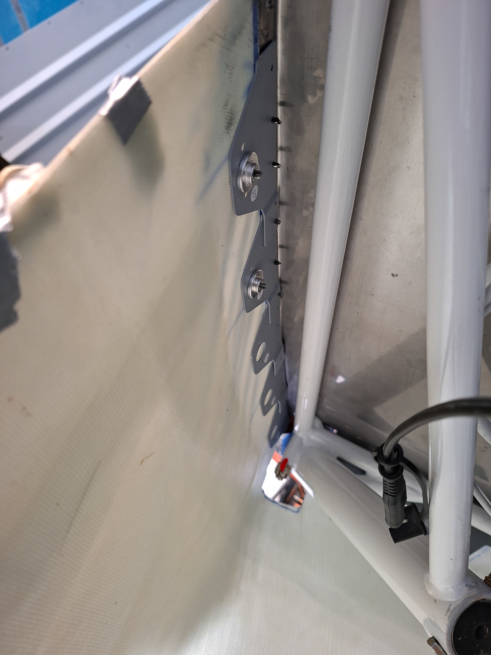
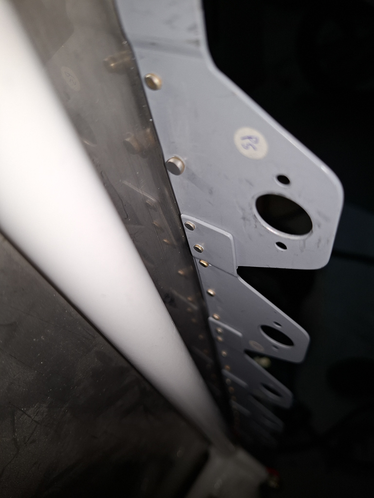
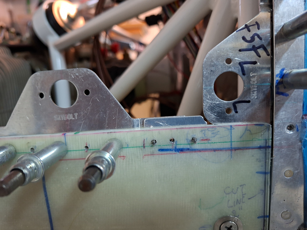
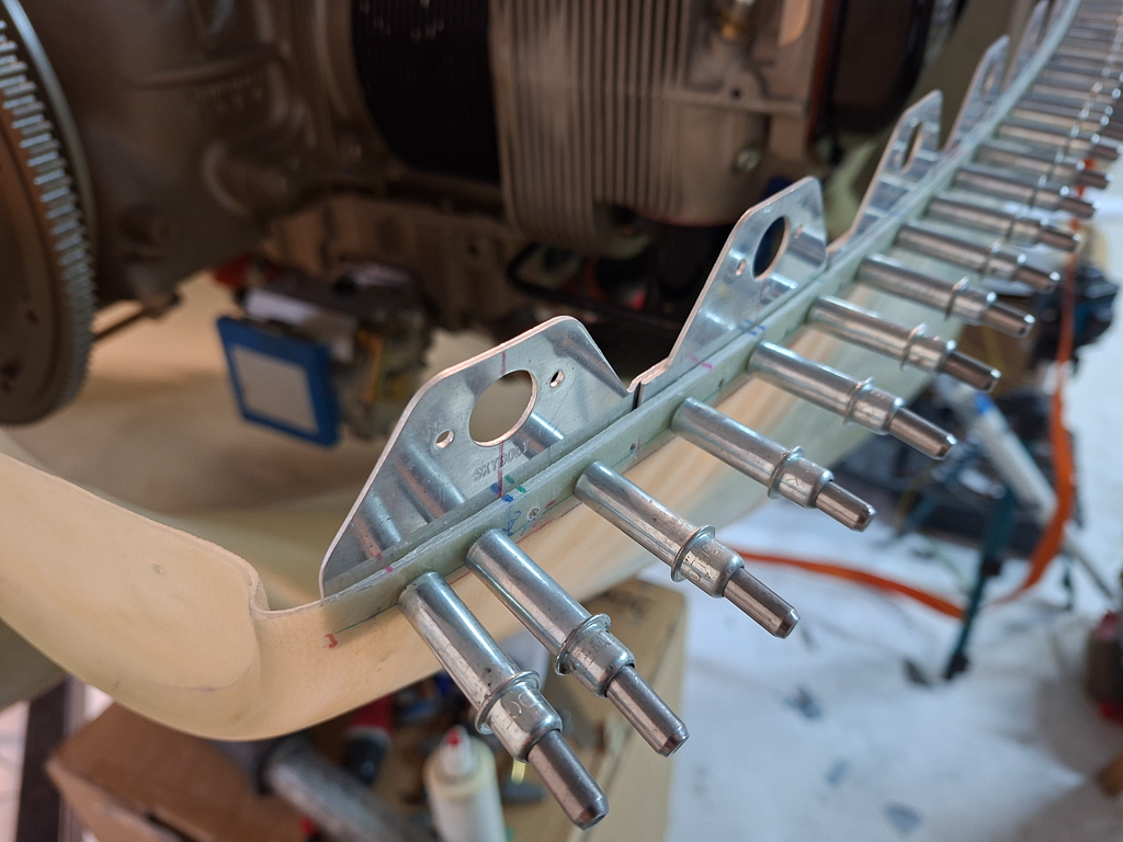
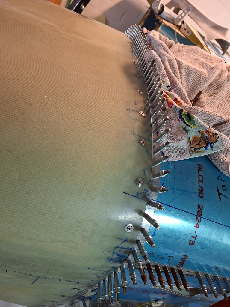
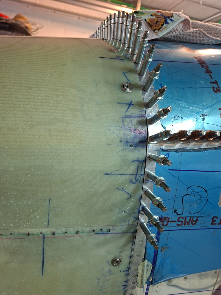
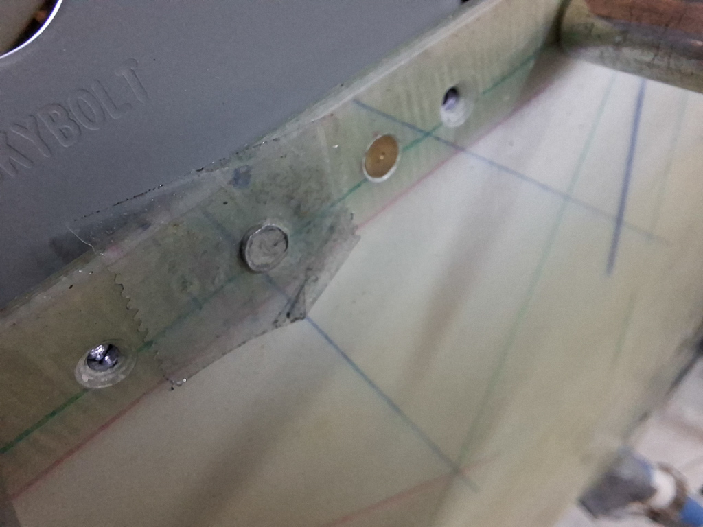
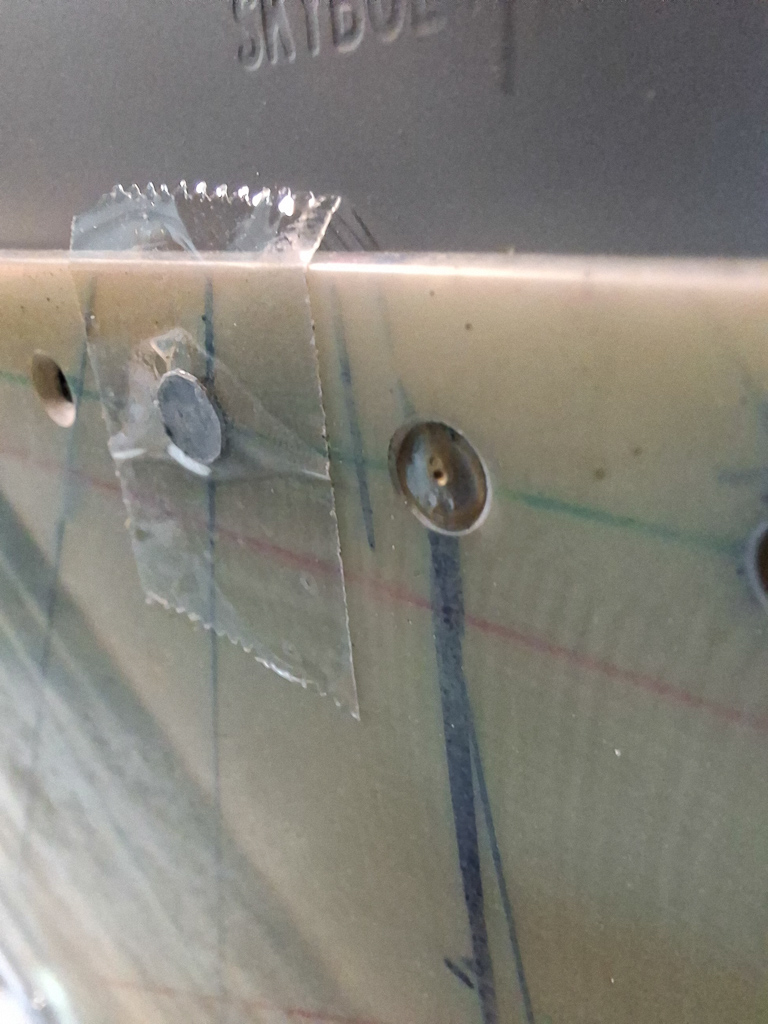
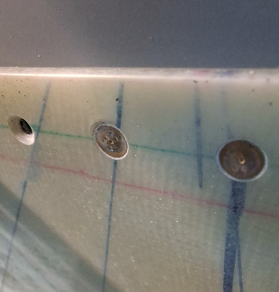
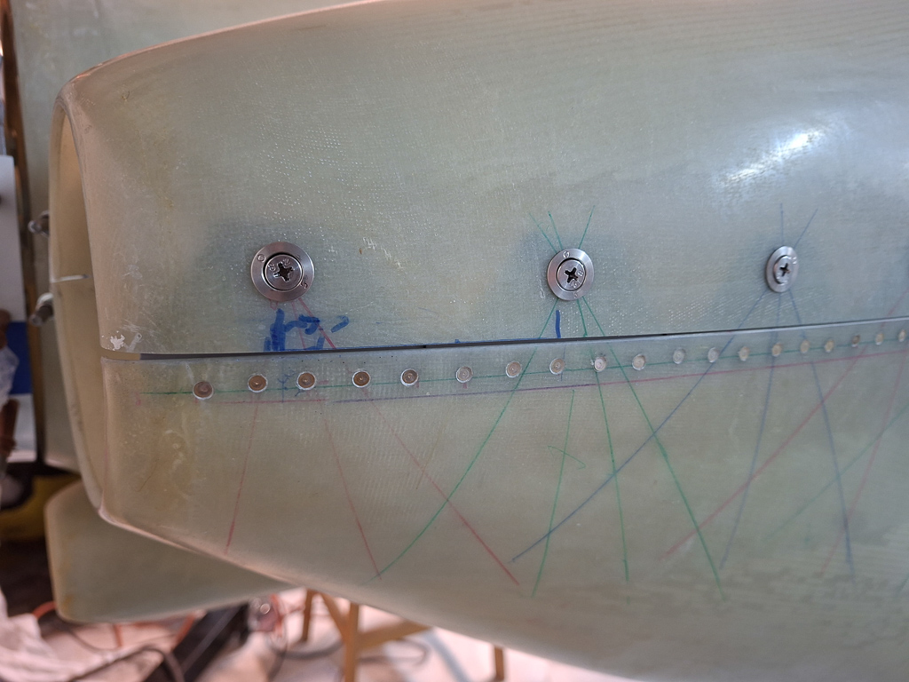
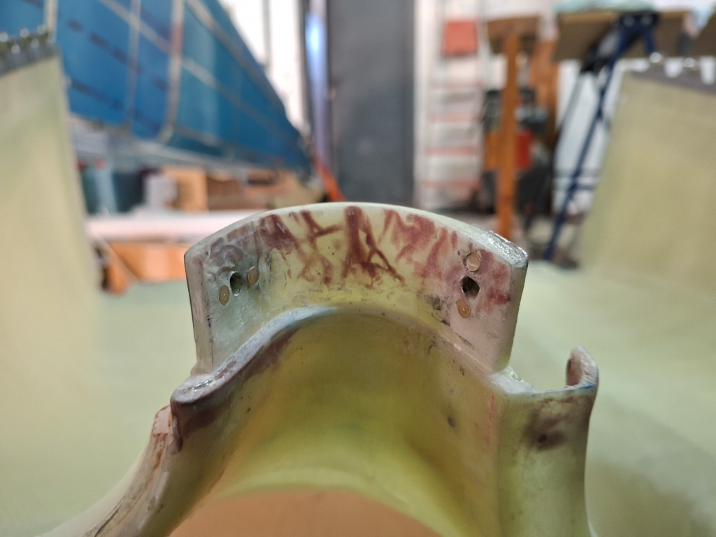
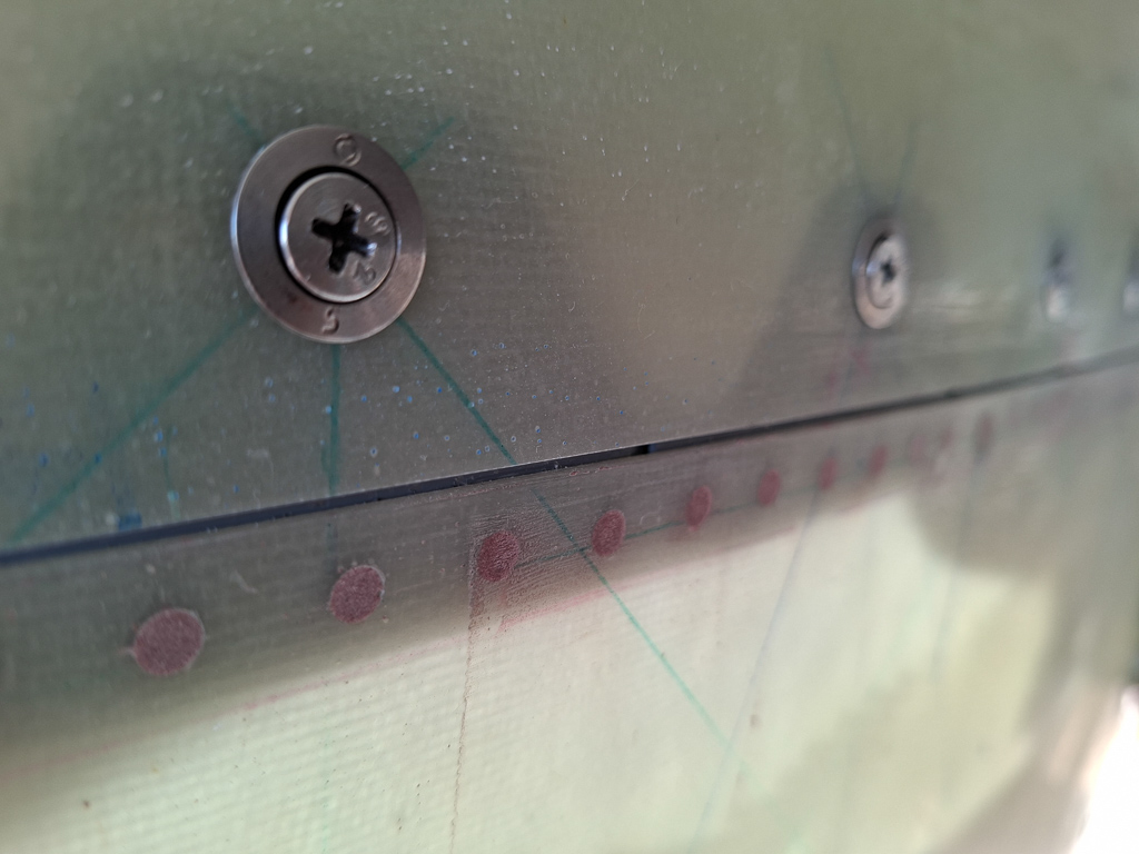
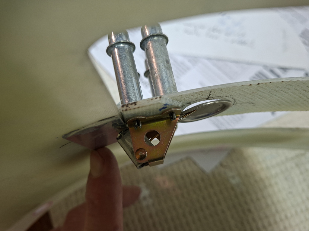
One of the things I discovered on the plans were some nutplates at the firewall recess top line which will be used to attach adel clamps that hold the oil pressure line to the transducer block. I noticed the I had already drilled the holes to AN3 #12 size but didn't make the nutplate ears yet. These are one leg nutplates so I used the nutplate as a template to drill the holes. As usual, slow rpm on the stainless steel drilling and a sharp drill bit. After drilling, I used the countersink cage to make the countersinks for the AN423AD3 rivets. Dimpling is no longer possible here as the firewall angle on the other side is rivetted. I asked the question to Vans and they confirmed just to countersing through the firewall plate into the firewall stiffener angle behind.
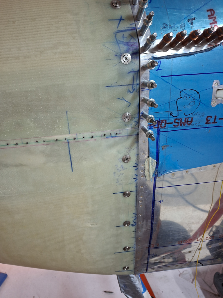
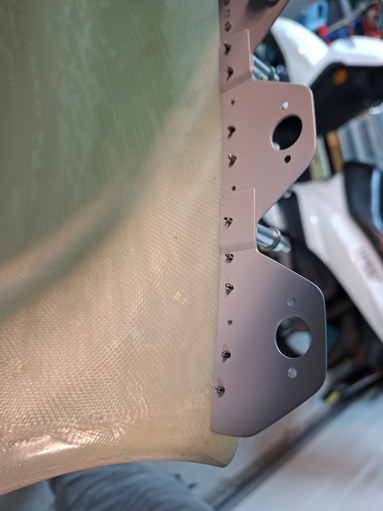
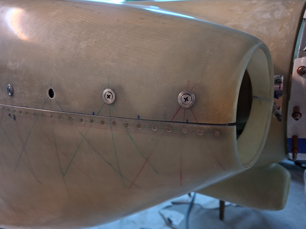
Other side of the recess, same procedure.
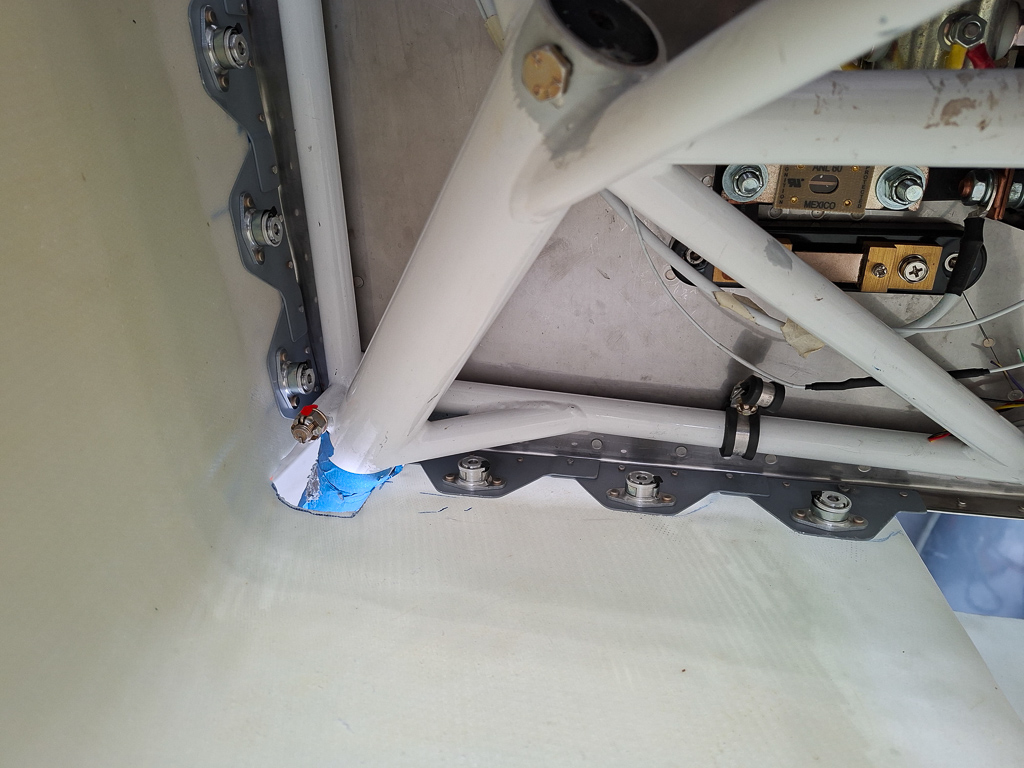
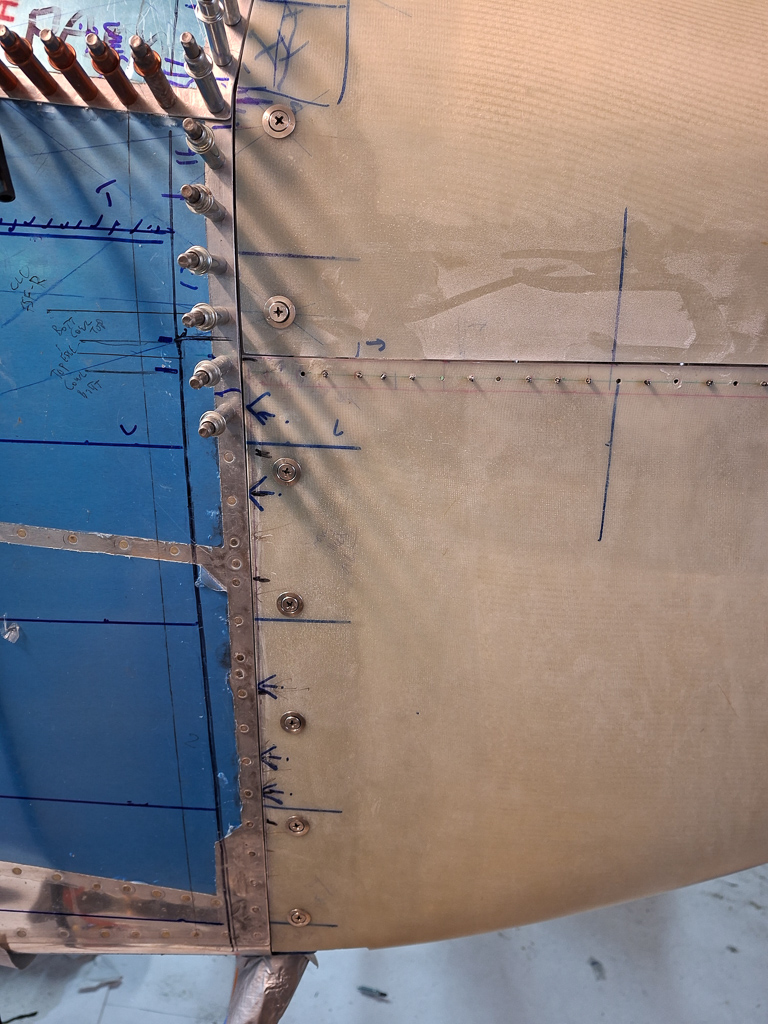
There is another nutplate below the recess in the vertical rivet line. This will be used to hold the FF-705 breather tube as indicated on OP-27 plan "oil system".
On some airplanes the hole is also used for the engine ground strap. I'm planning to go to the ground block with the engine ground cable.
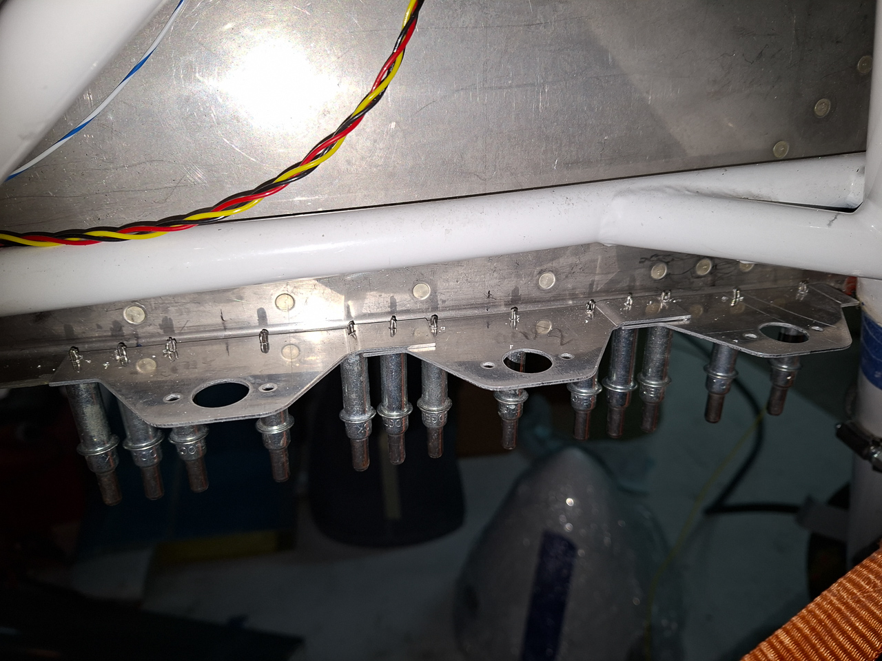
Squeezed the nutplates on. This was easy as the pneumatic squeezer could be used.
Then I countersunk the other nutplate
and used the rivet gun to set them.
Another step closer to finalising the firewall layout and hanging the engine
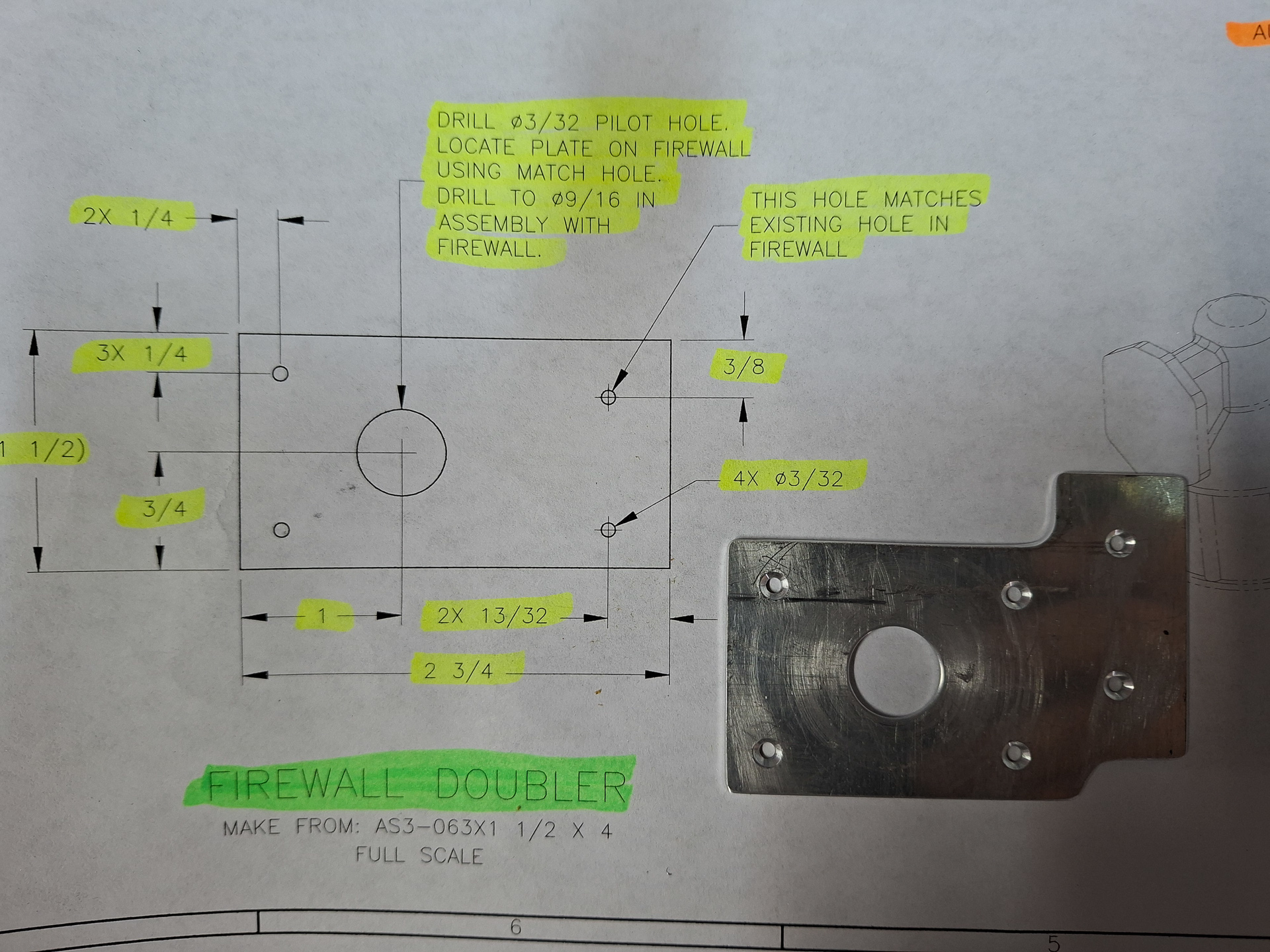
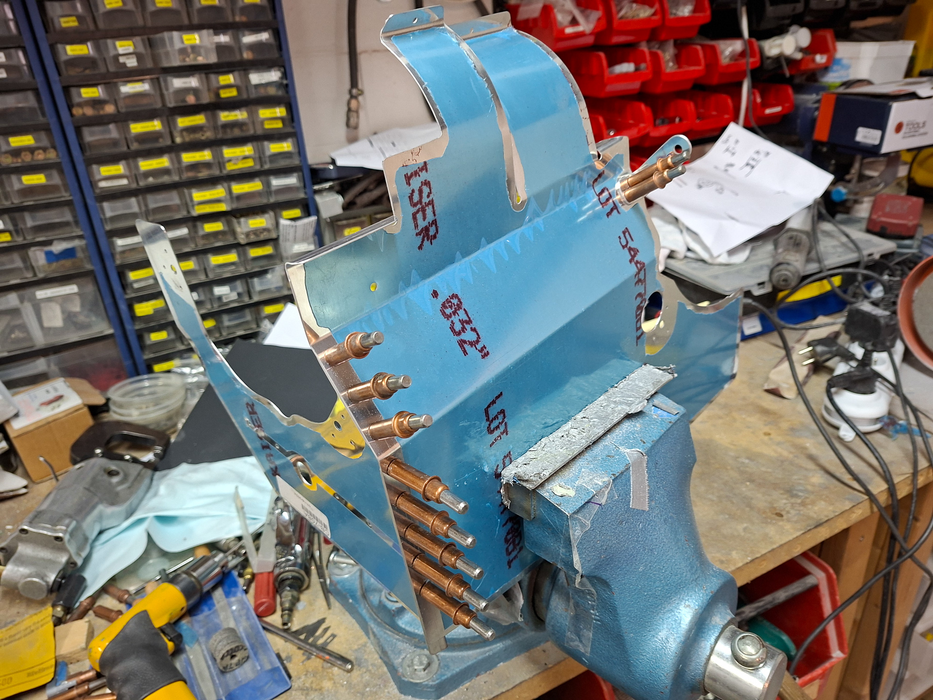
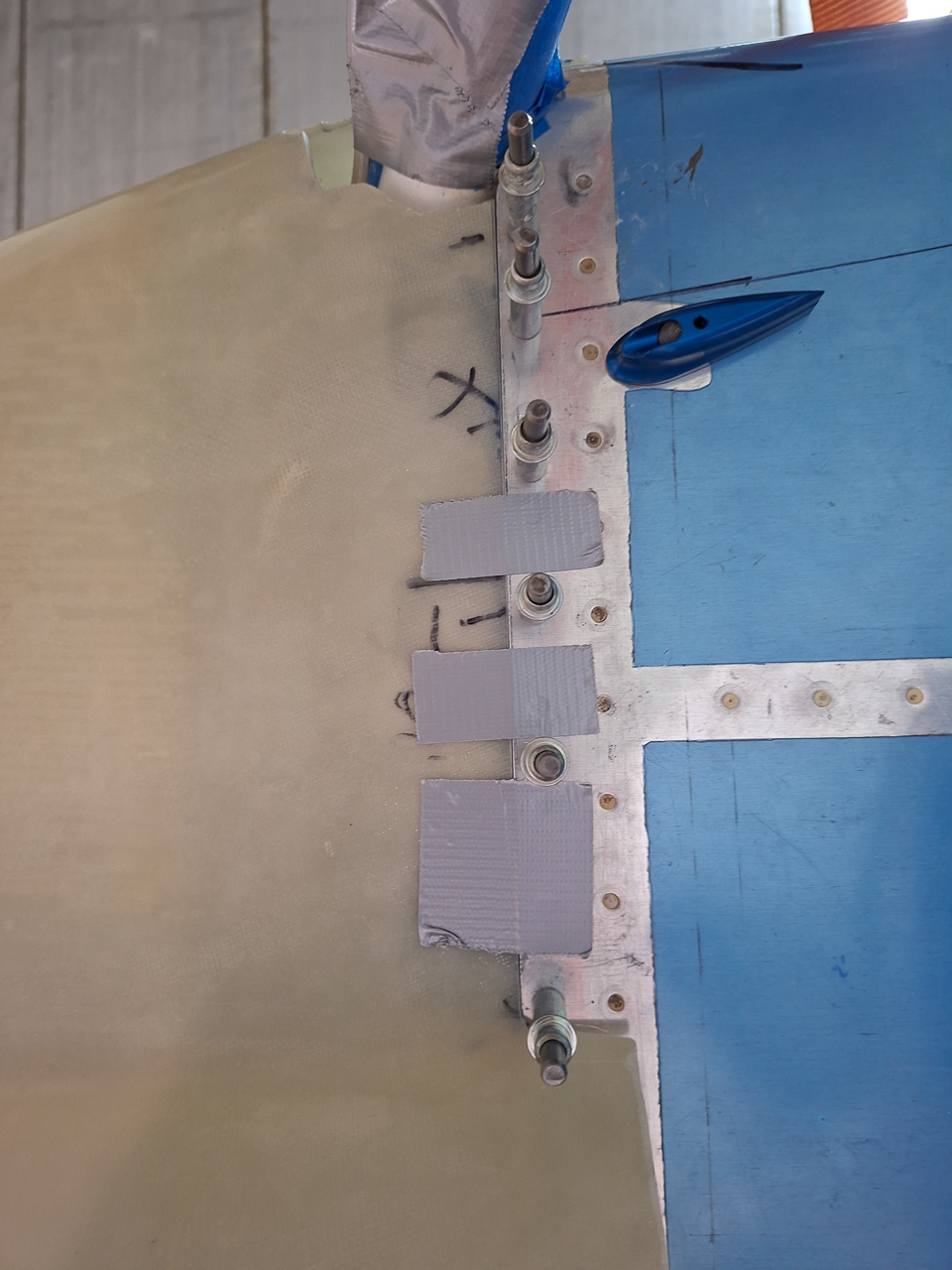
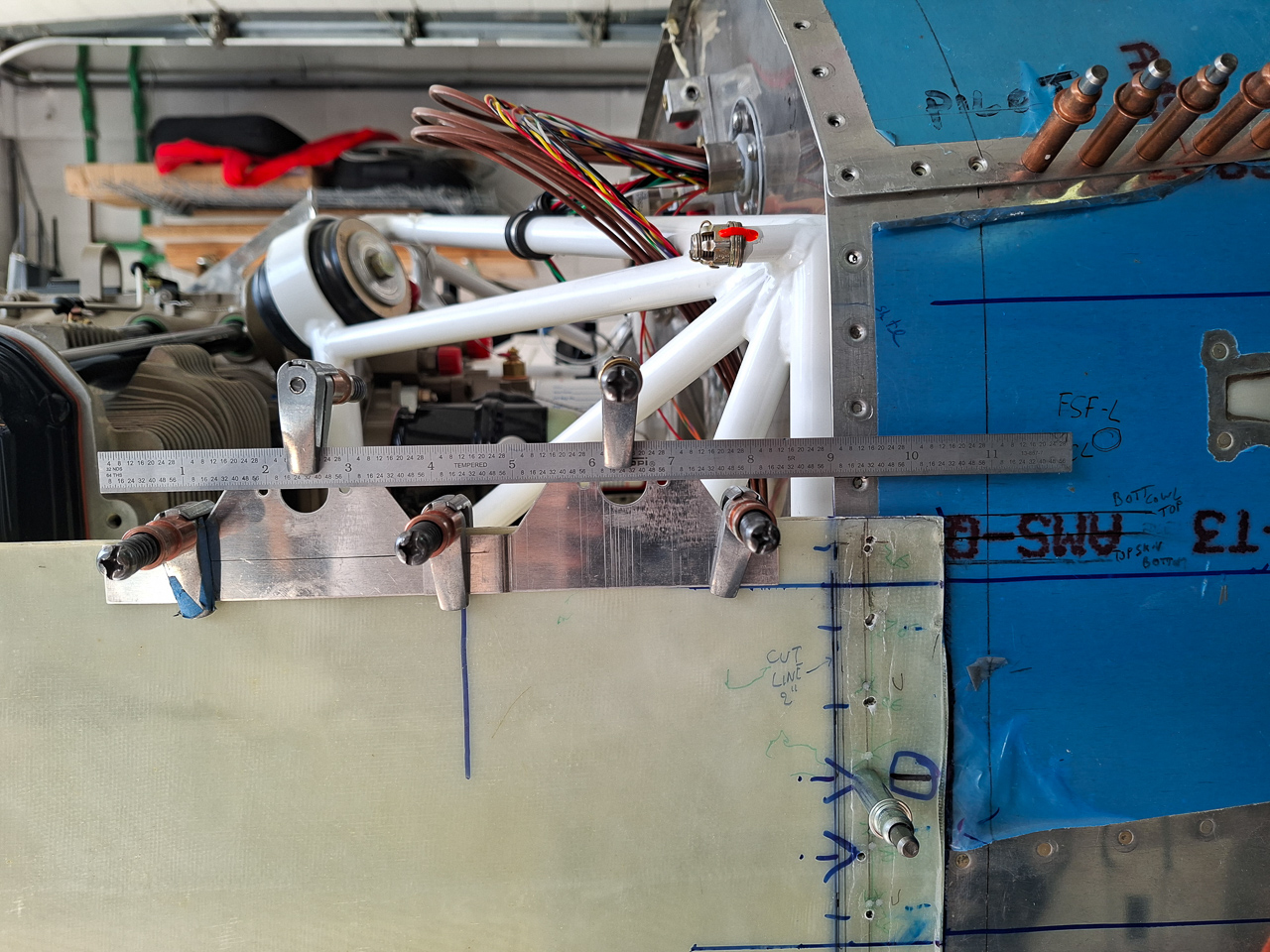
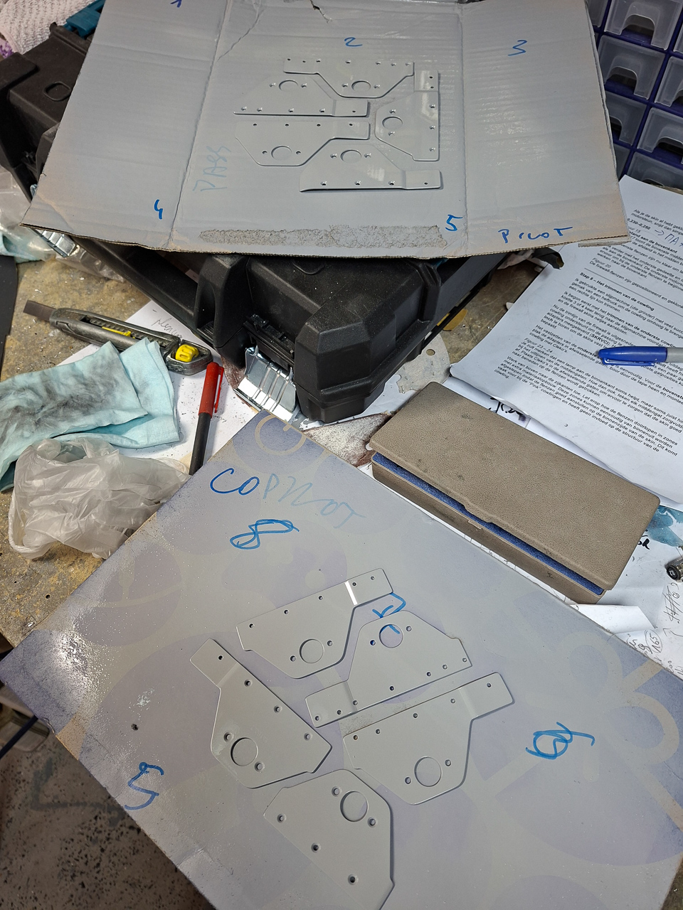
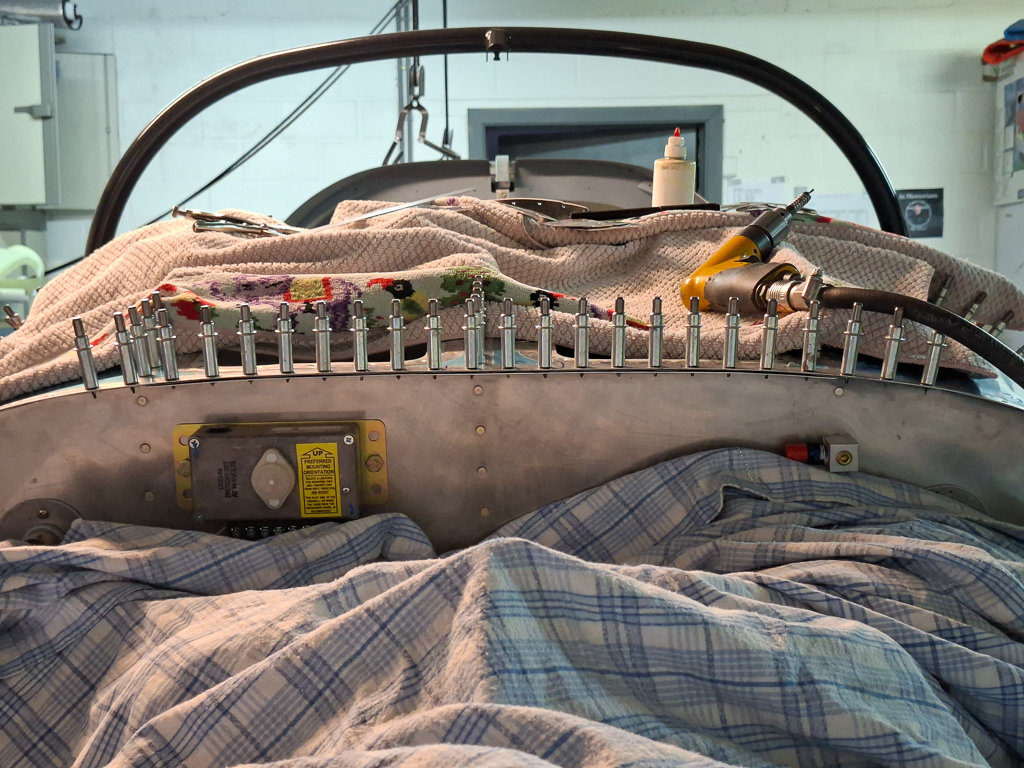
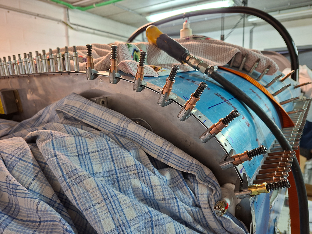
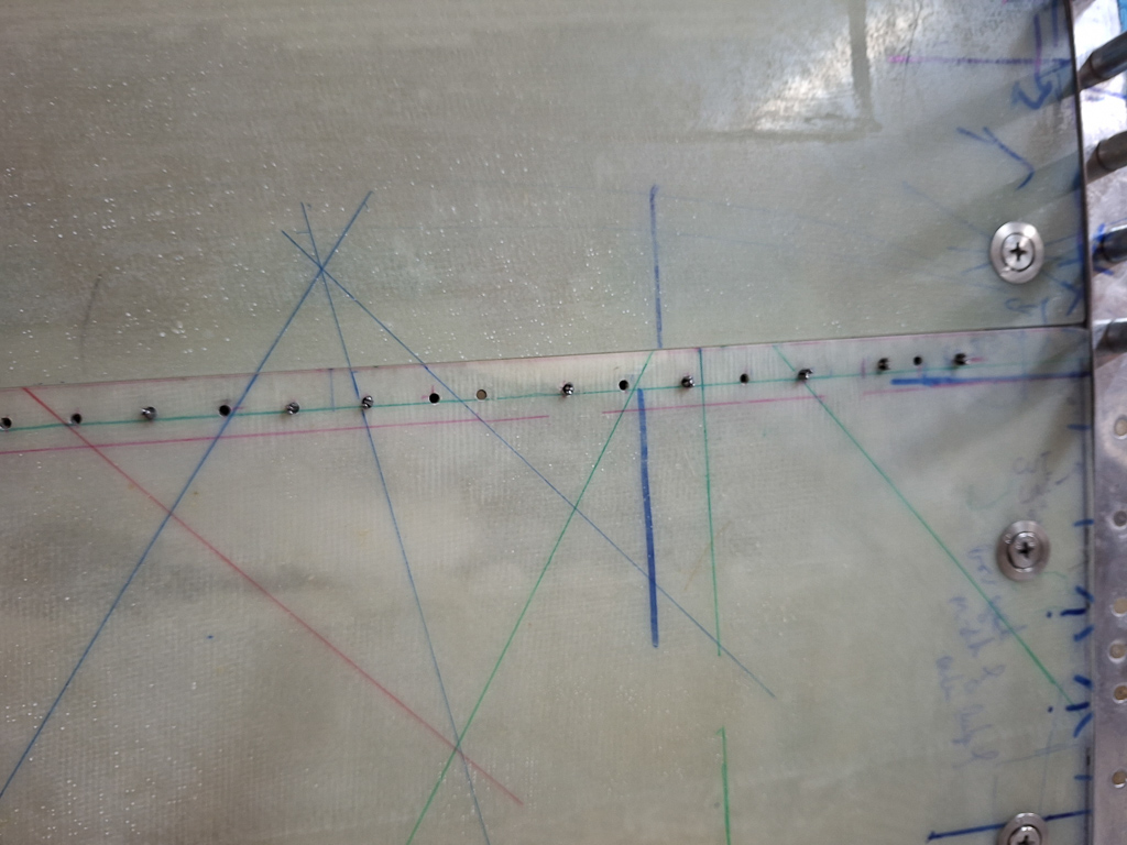
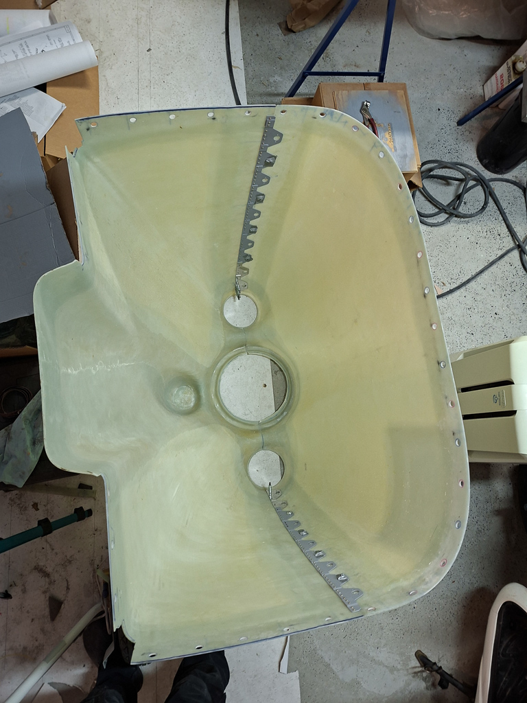
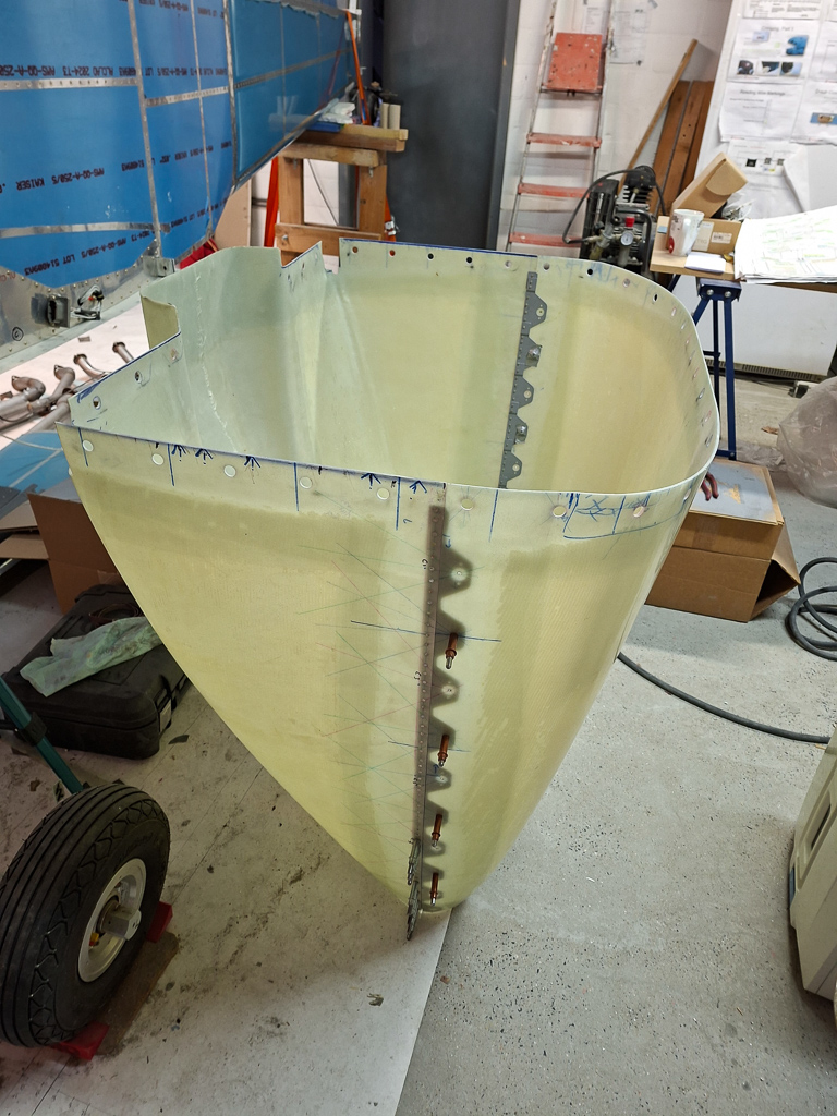
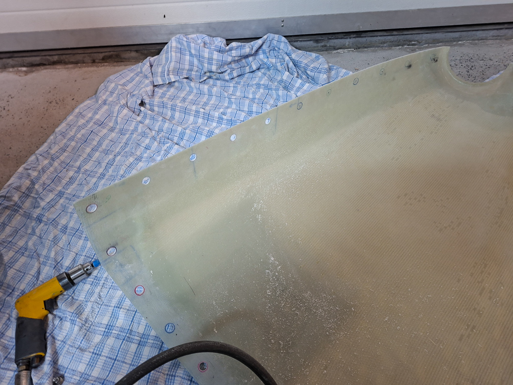
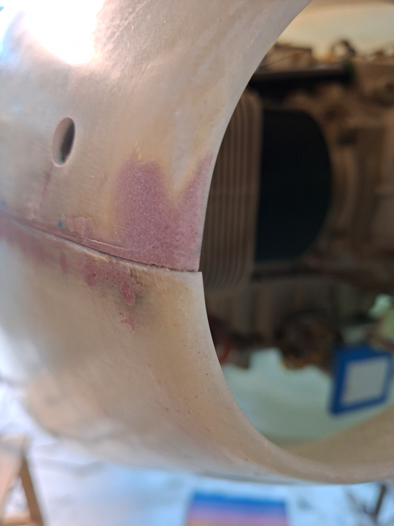
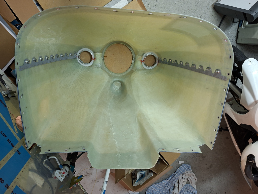
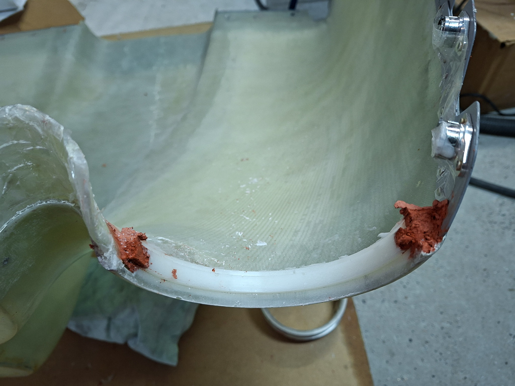
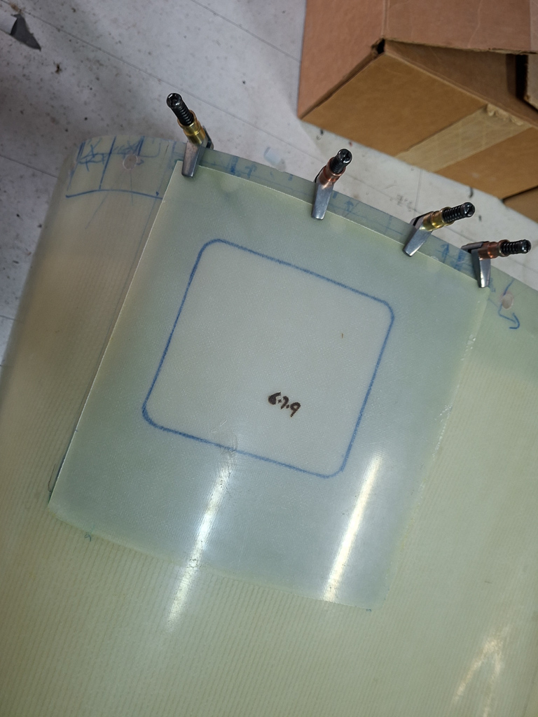
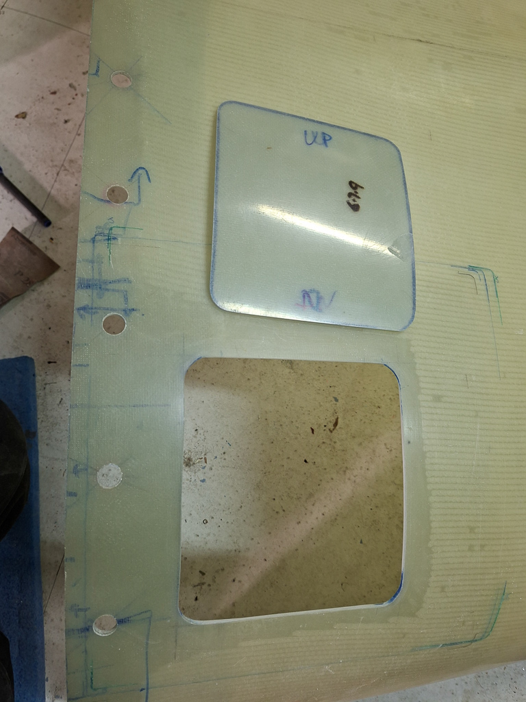
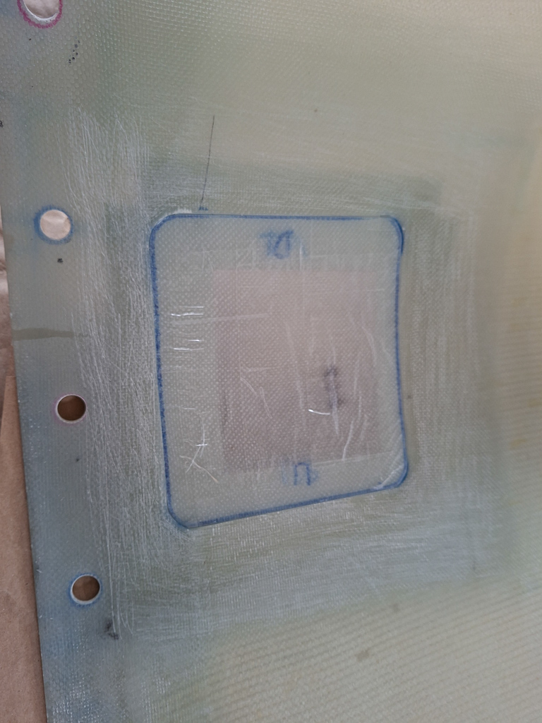
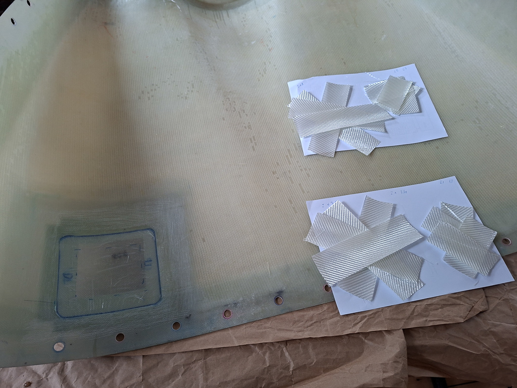
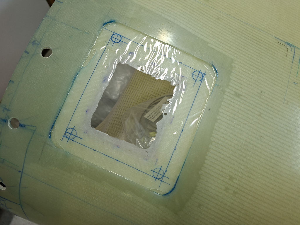
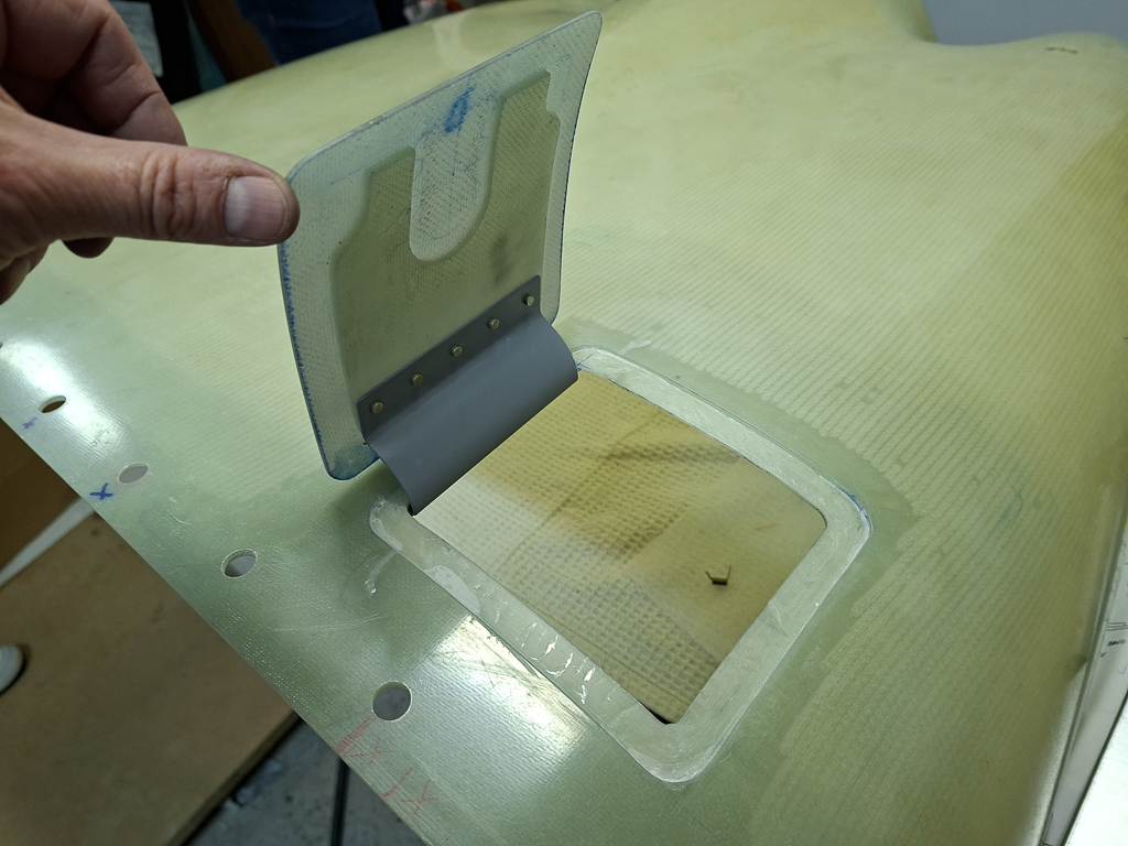
05/07/25 - Fuel pass through doubler plate - 6h30
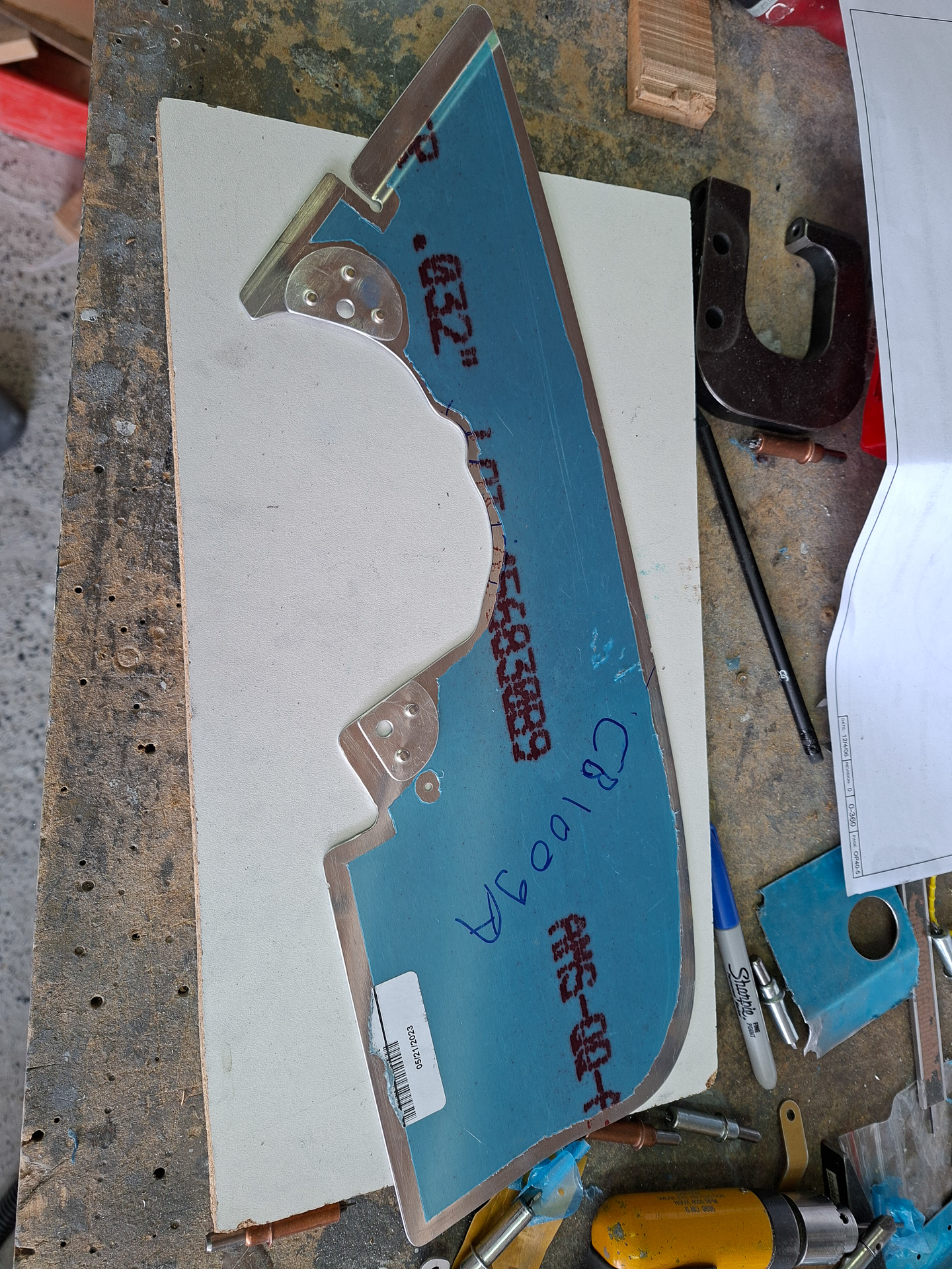
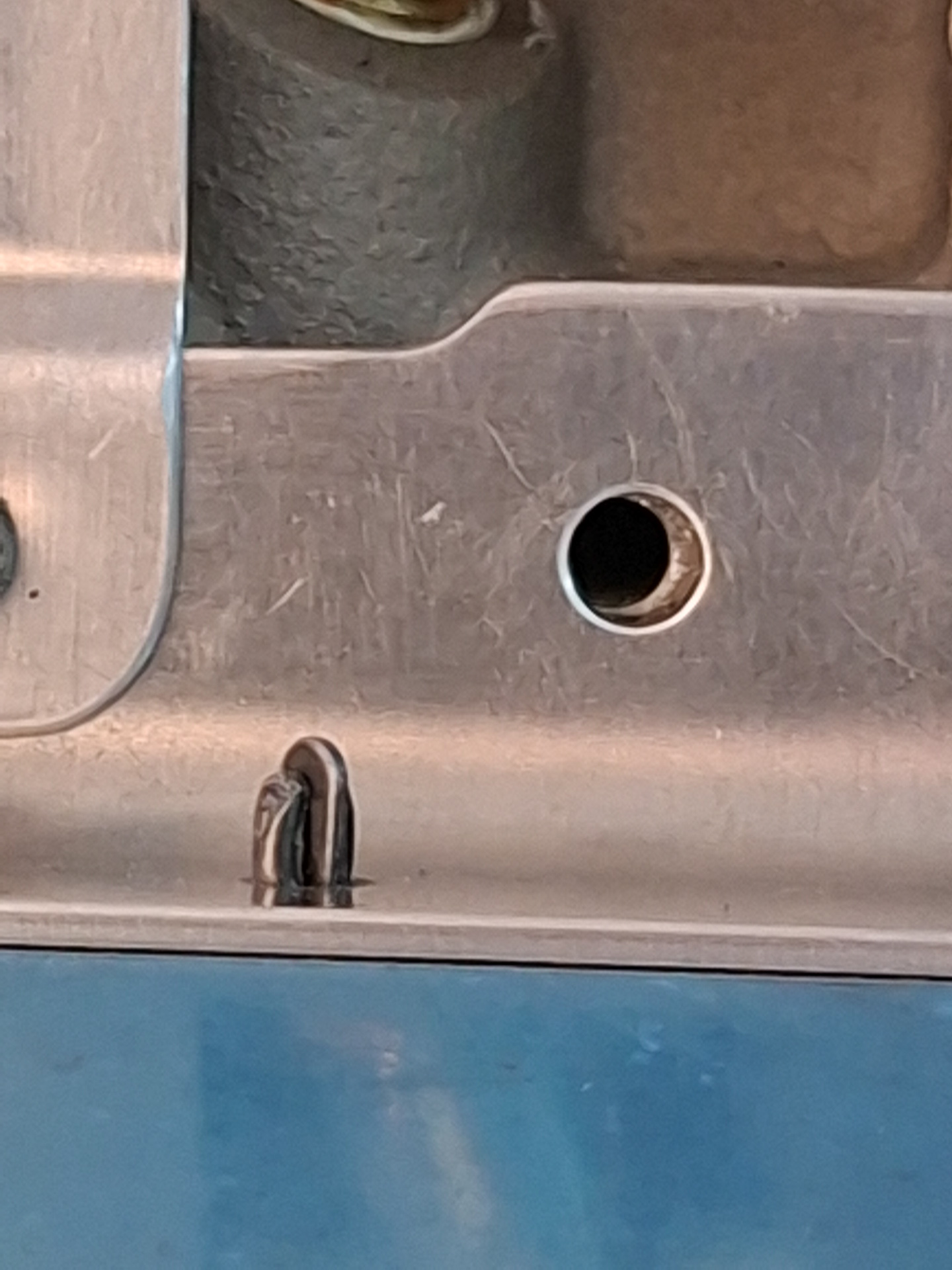
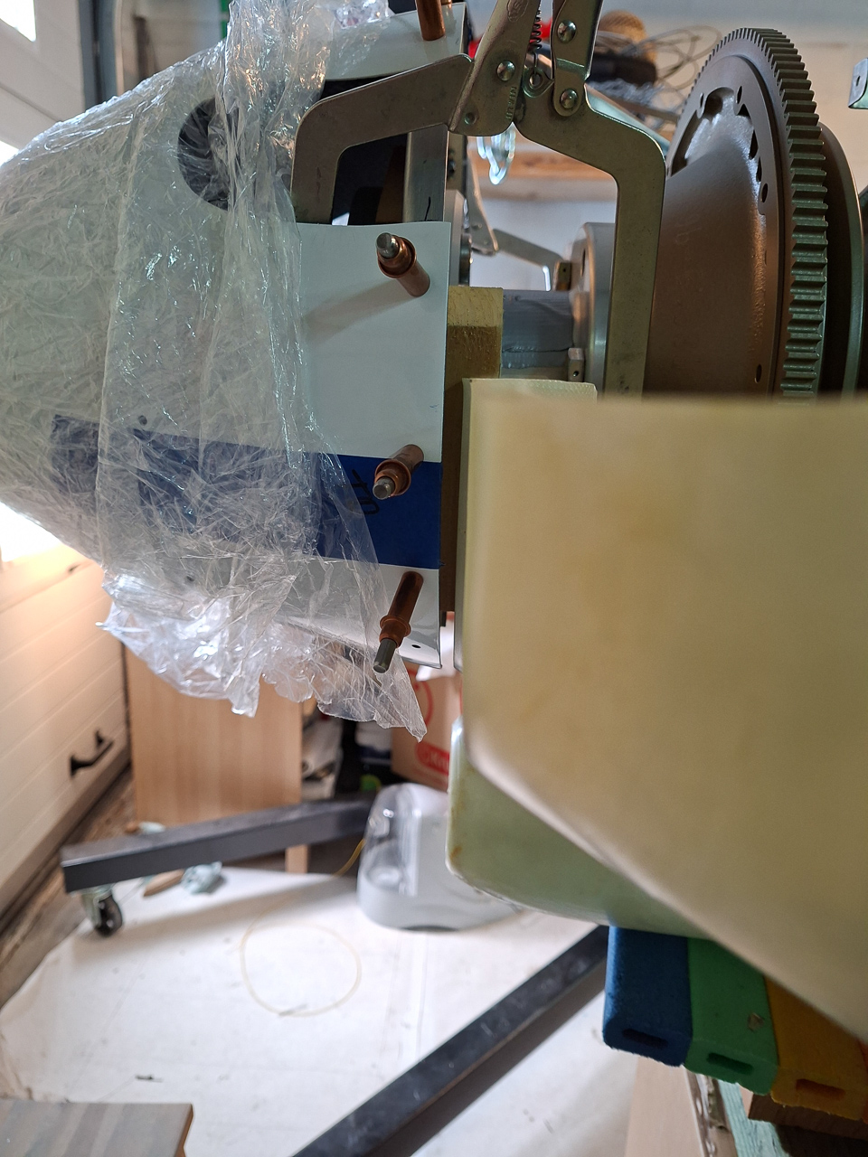
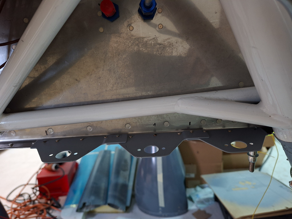
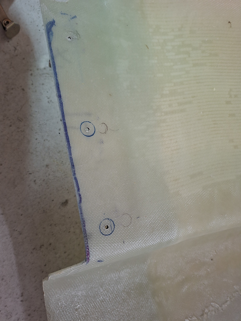
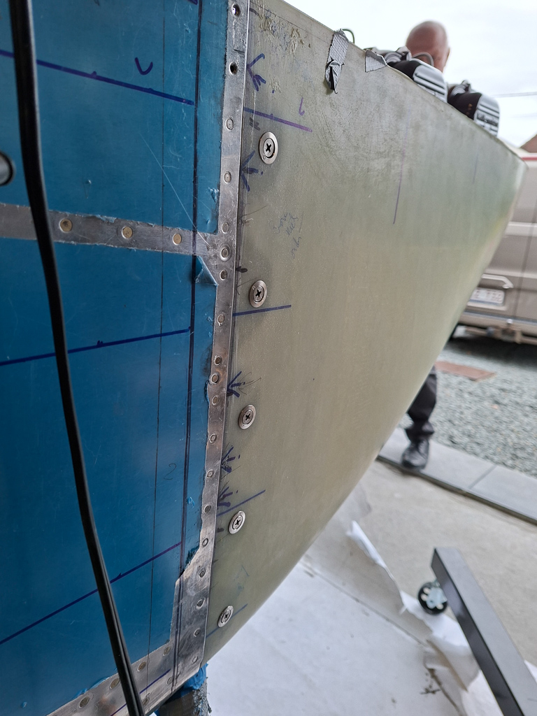
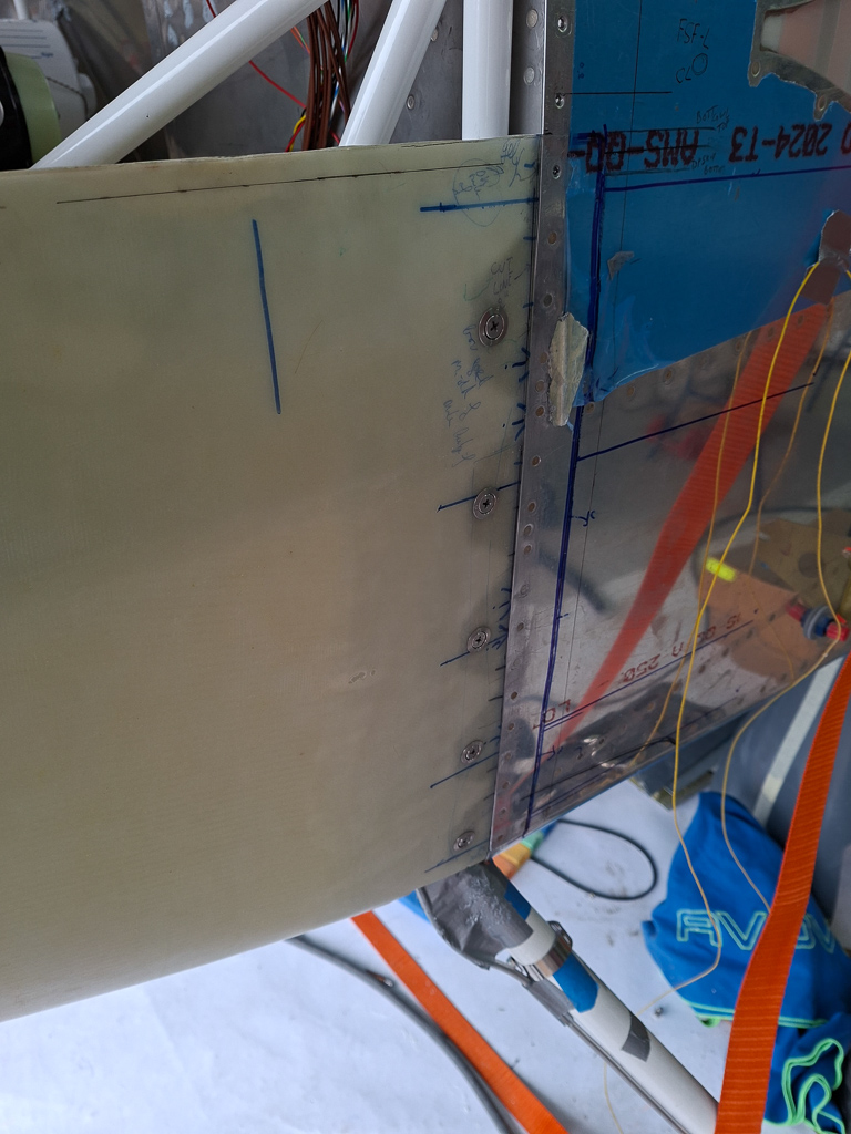
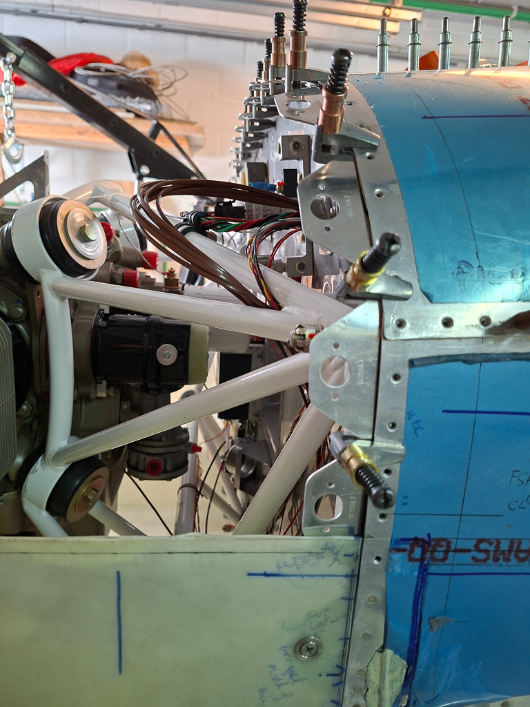
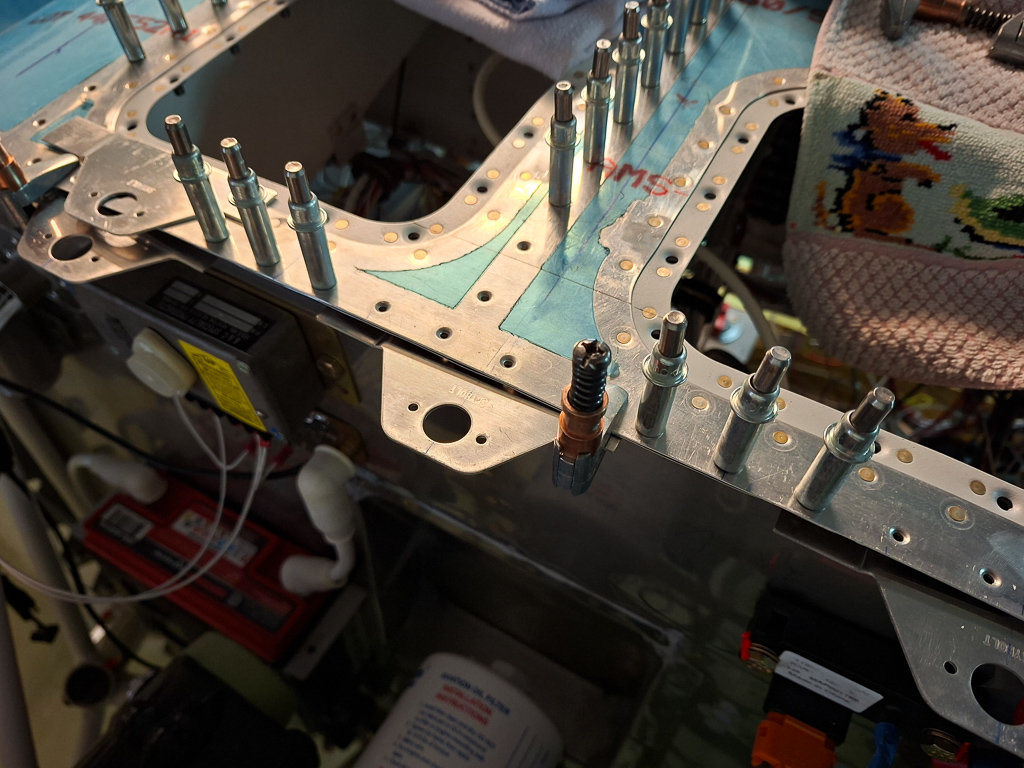
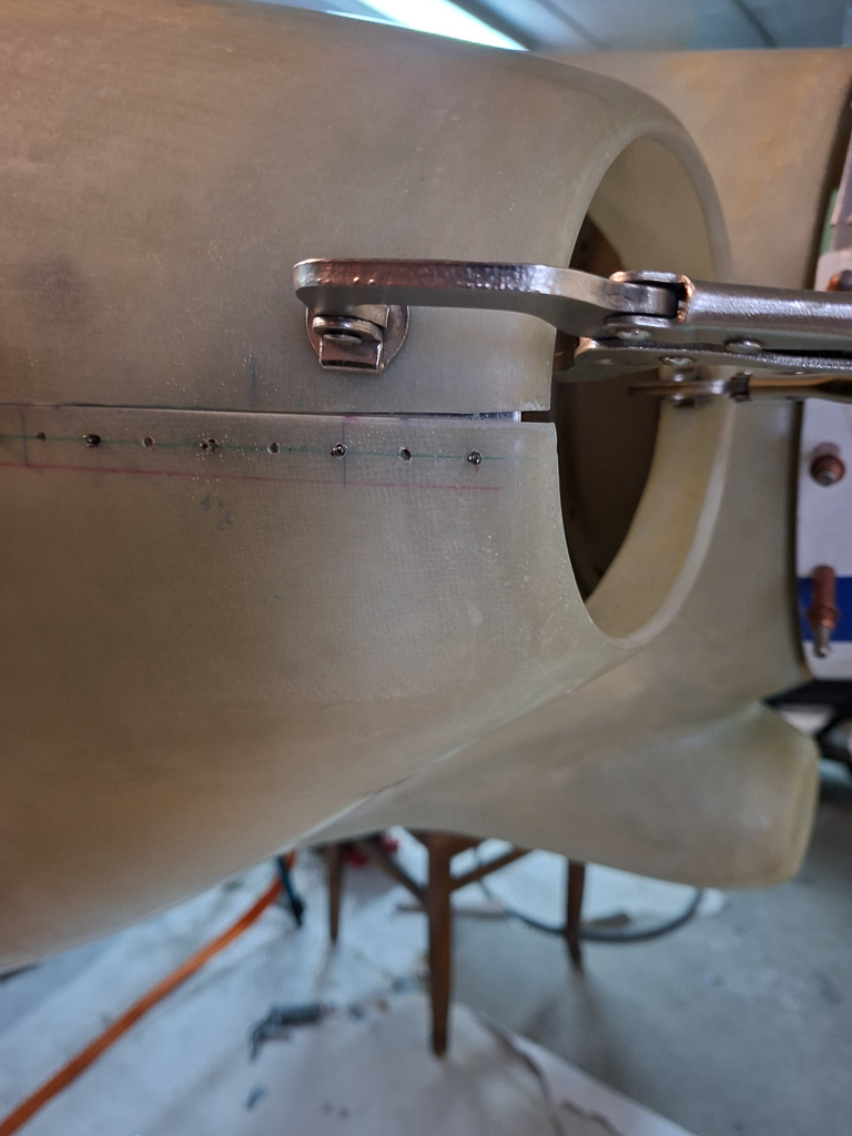
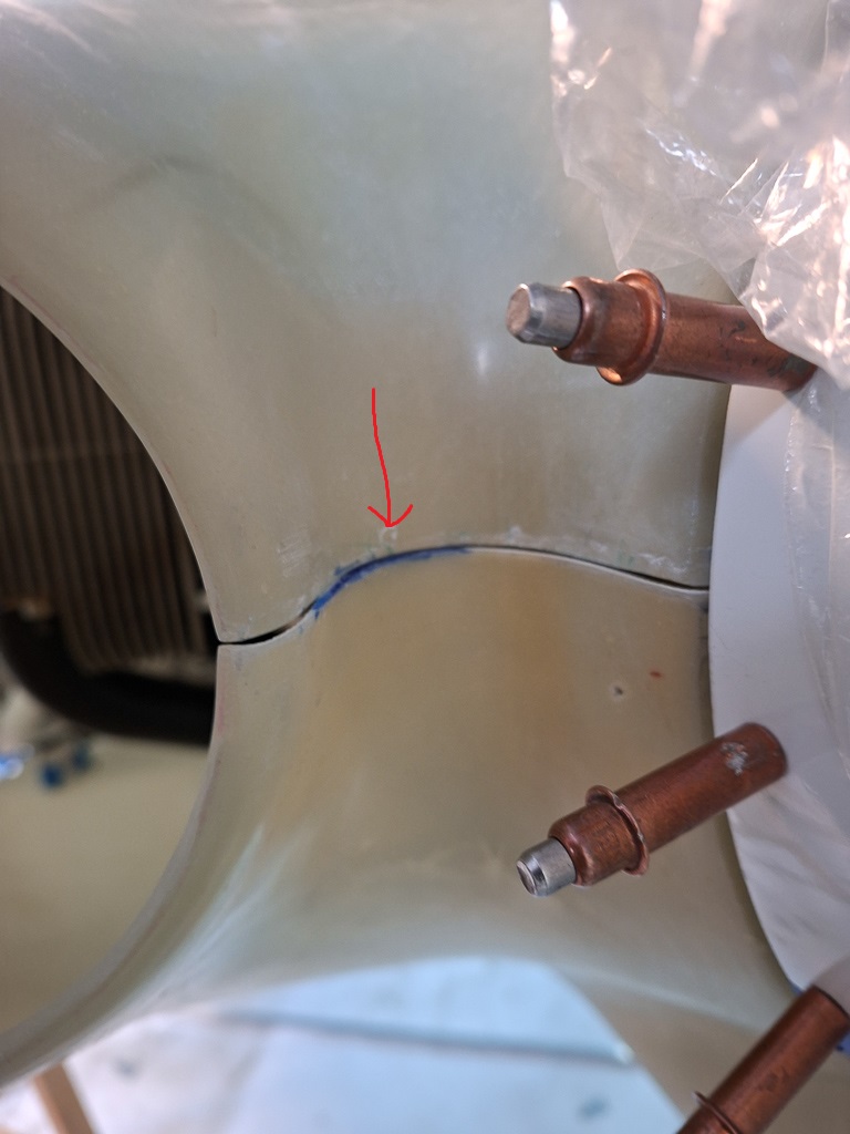
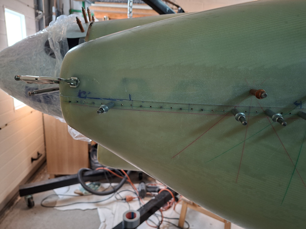
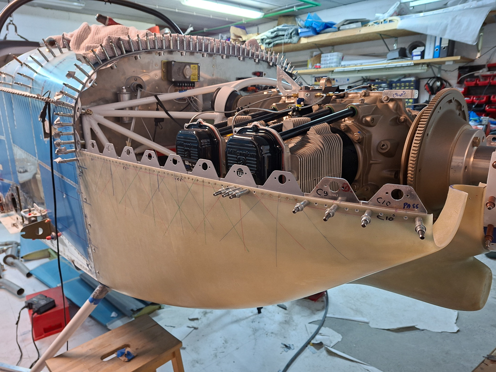
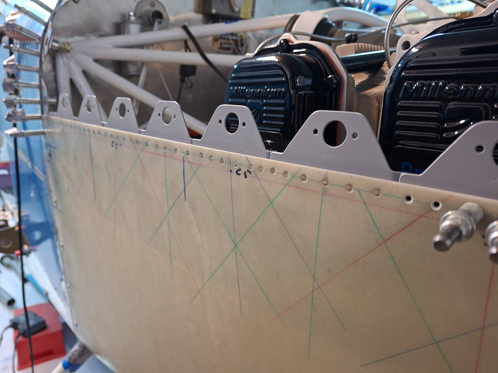
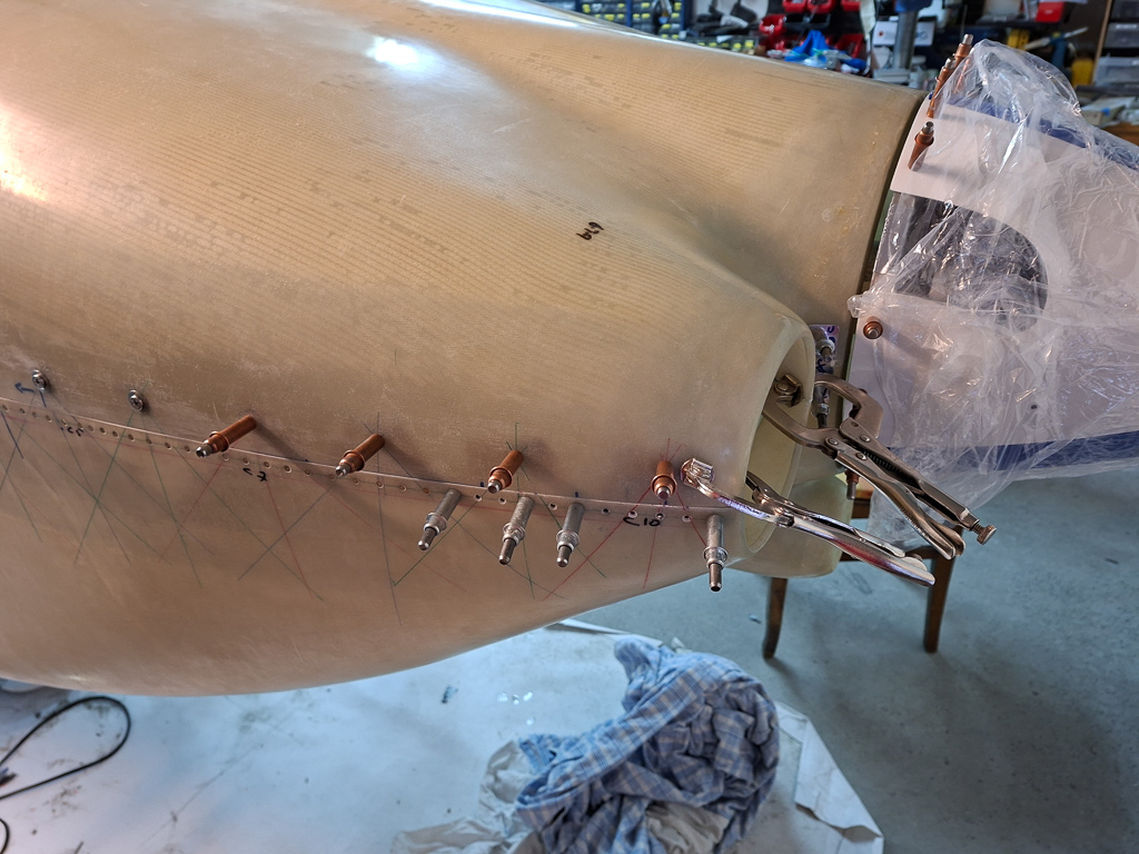
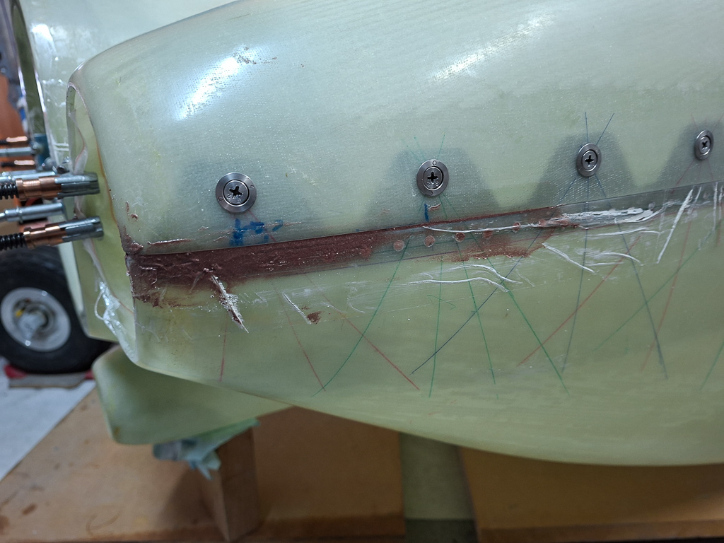
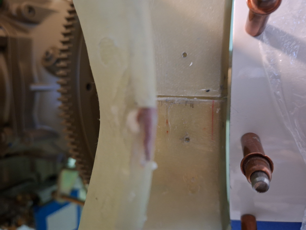
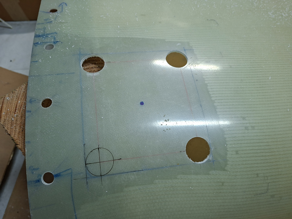
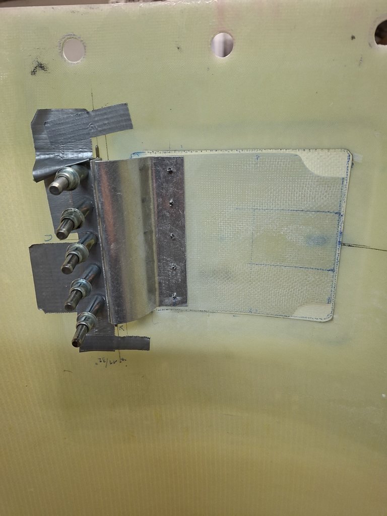
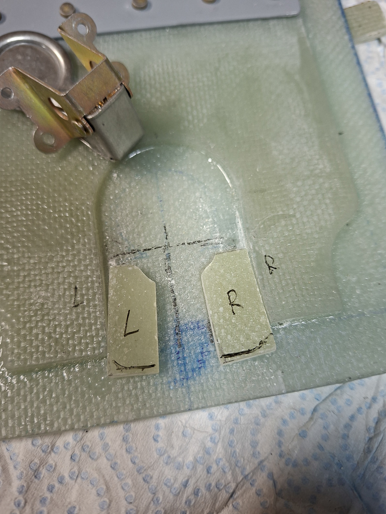
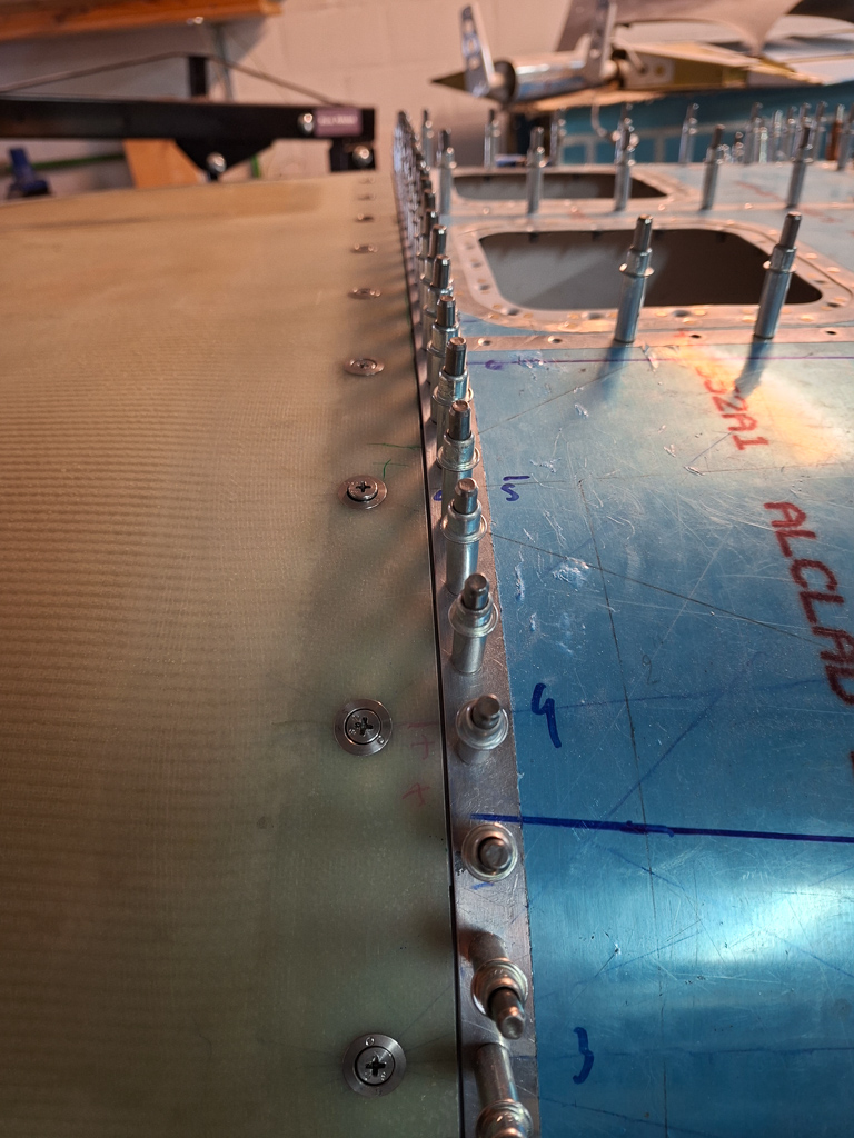
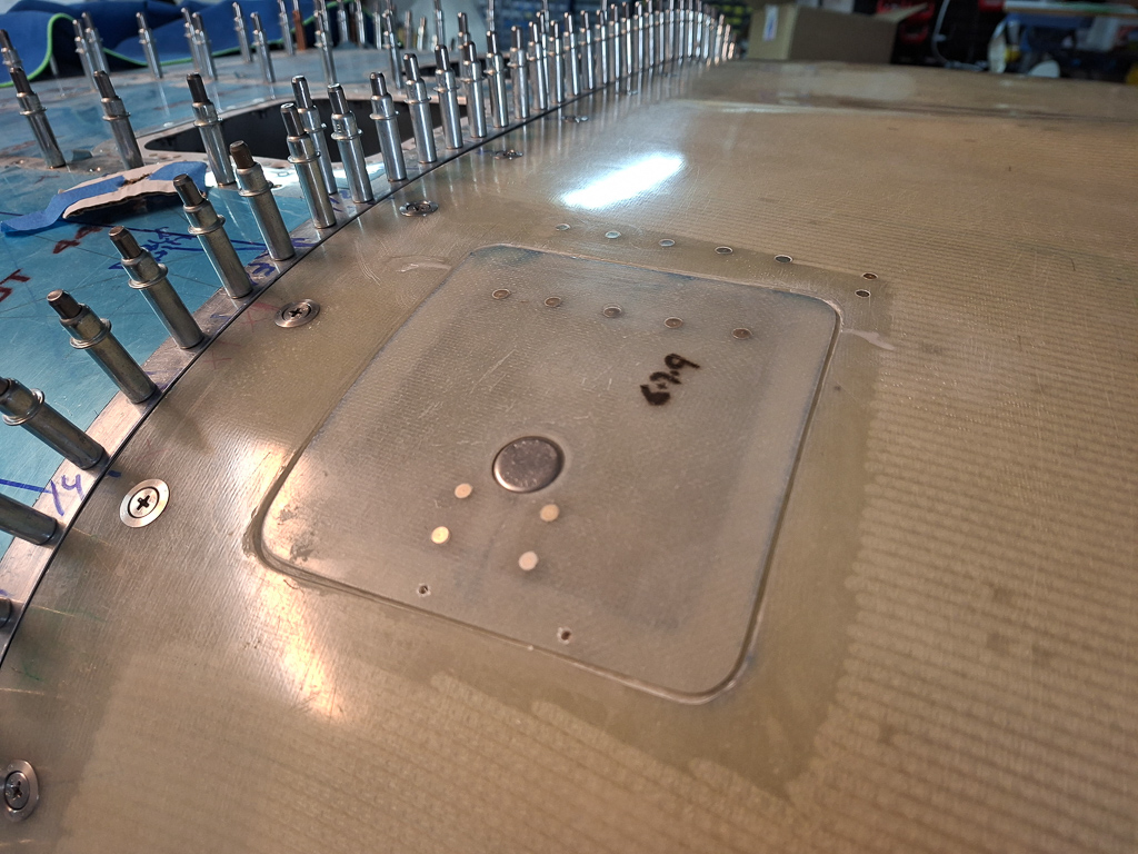
Some more firewall work. I have been postponing the fuel penetration pass through for a while as I though this would be something I would do after hanging the engine. However, now that I have fysically seen the engine and have seen the location of the mechanical fuel pump, I'm pretty sure that the location as it is indicated on the plans on OP-32 "IO-360 fuel system" will work fine.
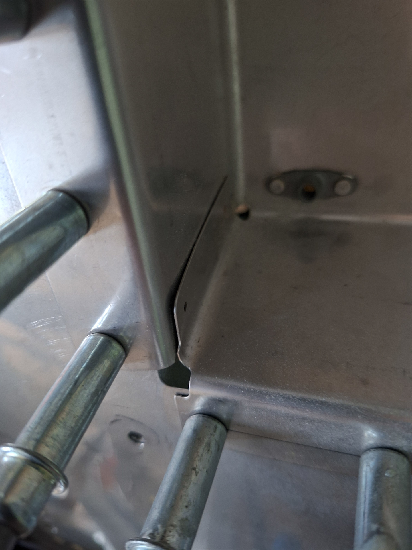
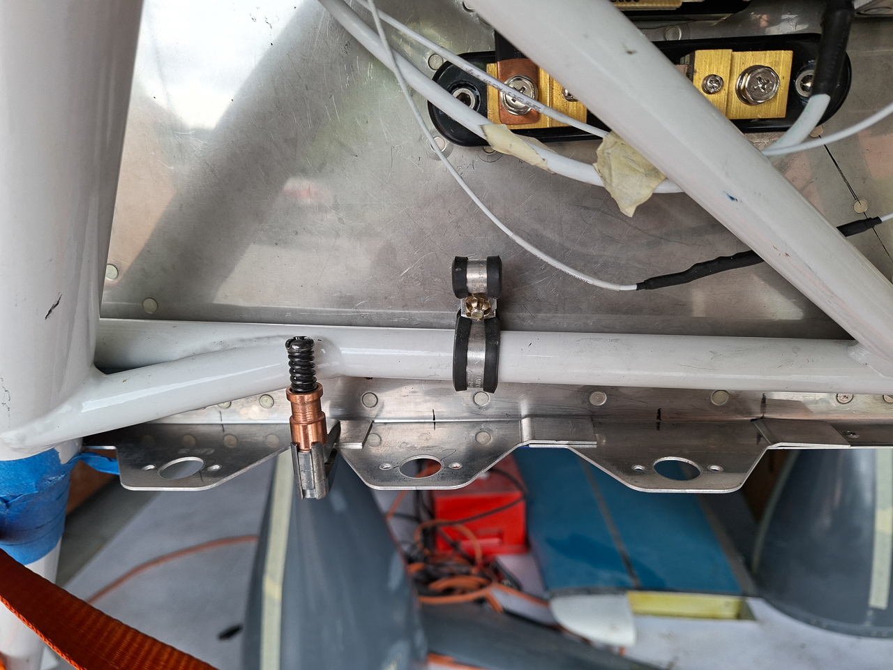
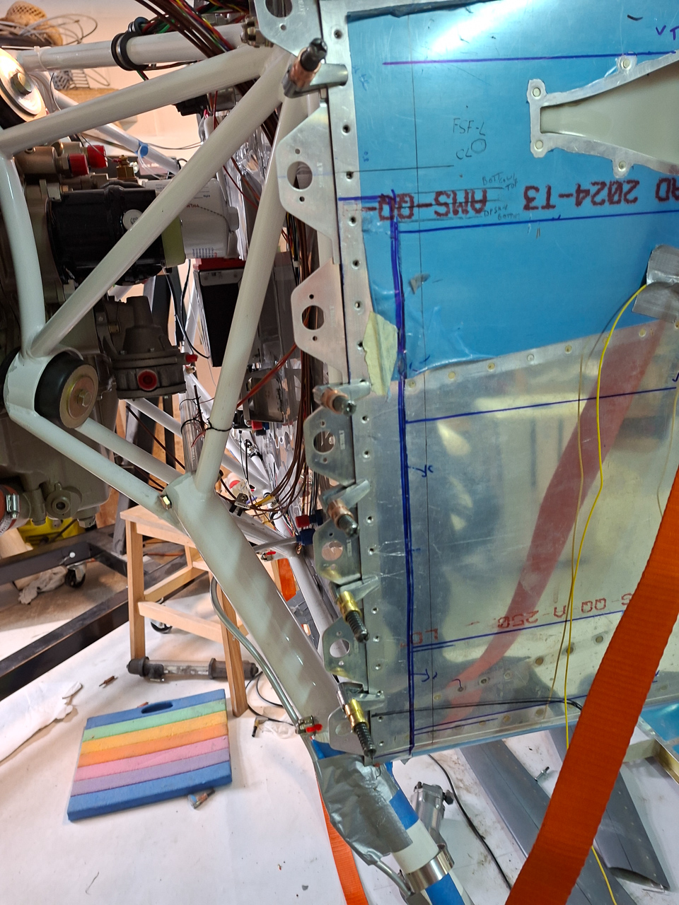
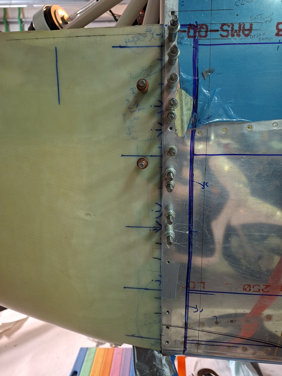
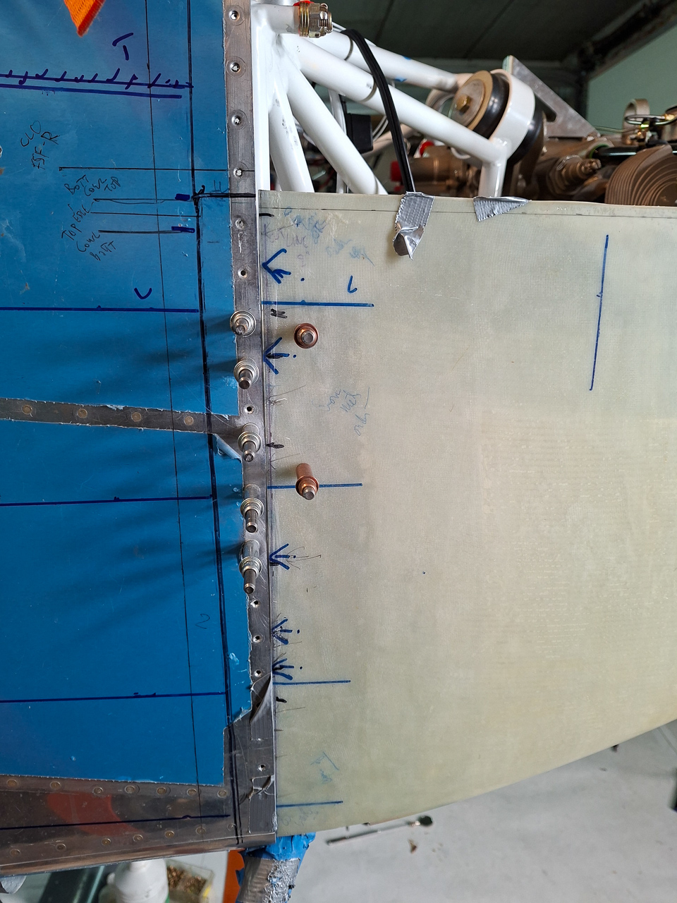
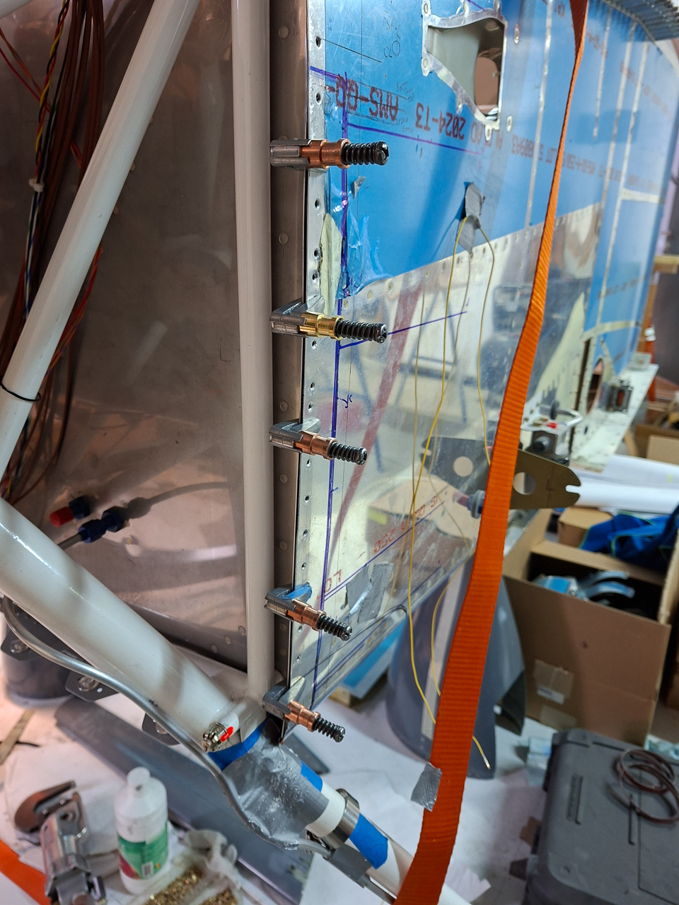
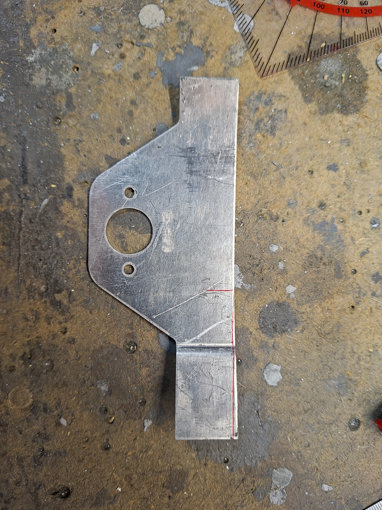
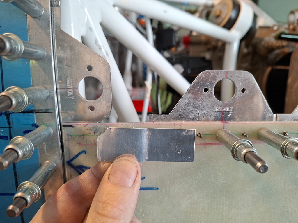
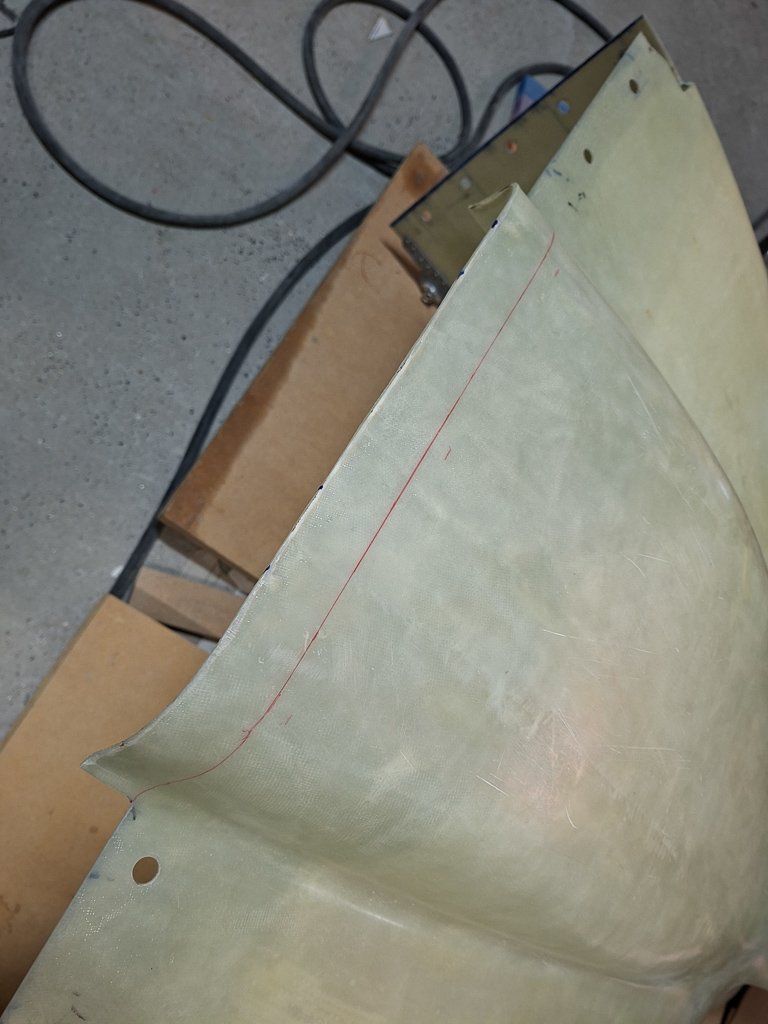
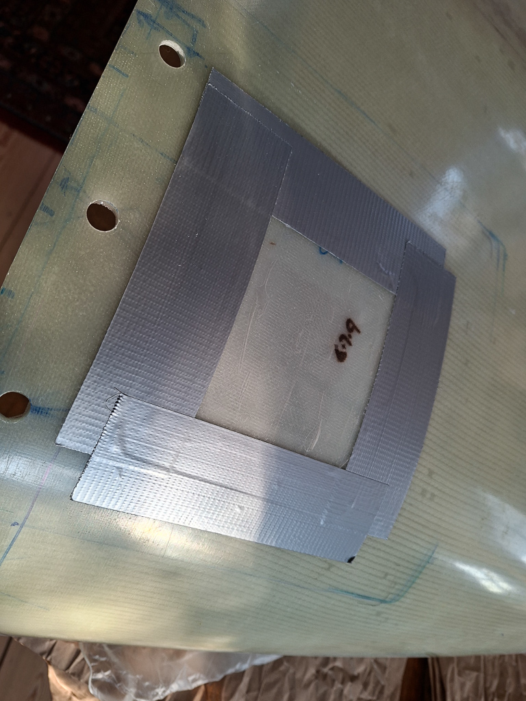
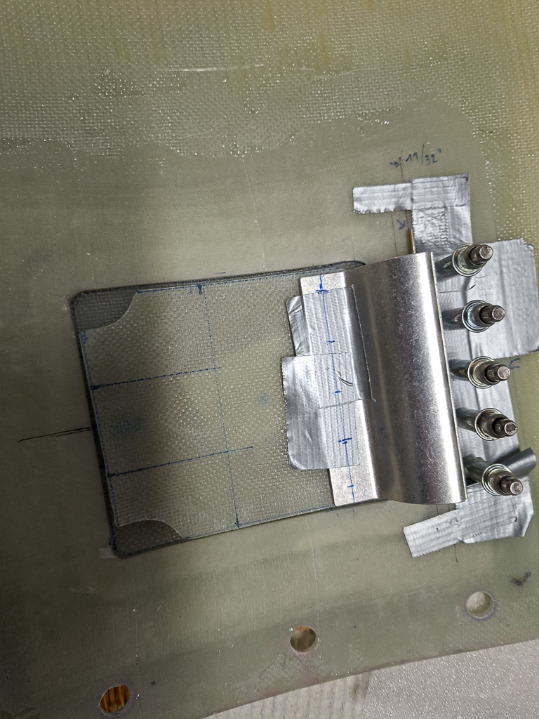
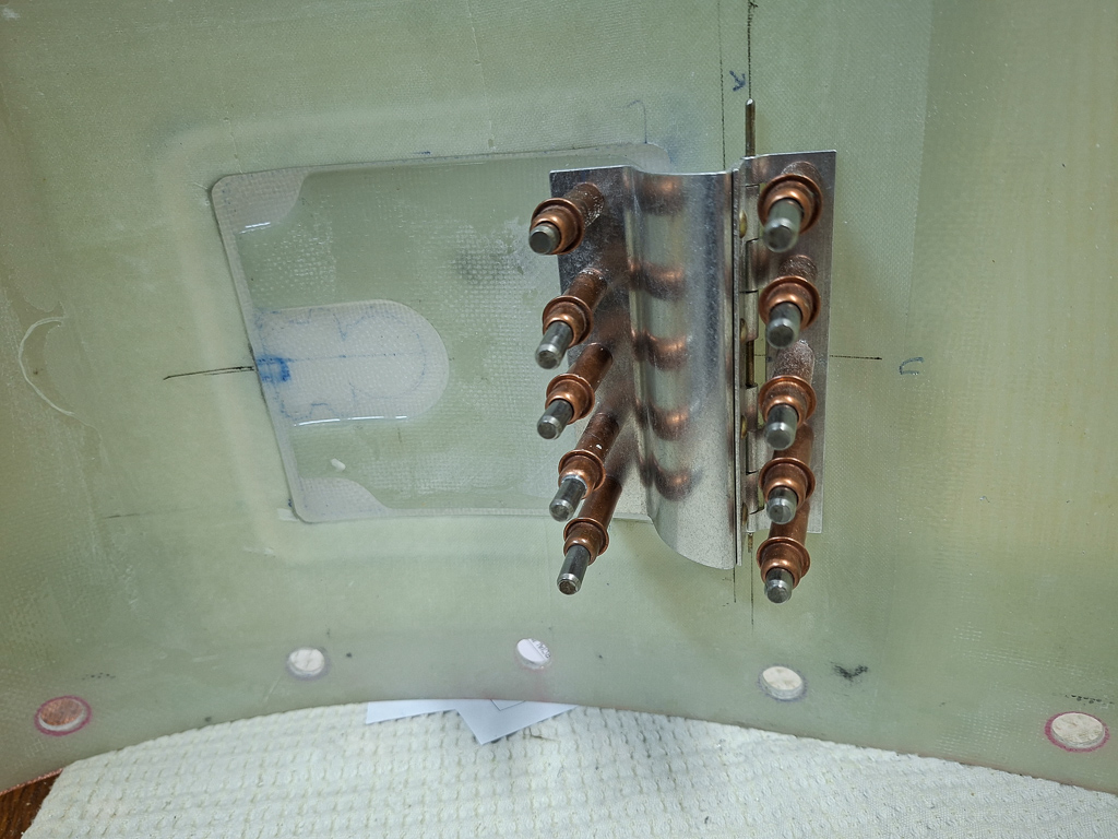
One problem though is that the fuel firewall doubler plate doesn't fit the as the leg of the starter contactor is in the way. Started looking on the forums for images of how others have done it and at first I was committed on keeping the original doubler shape and placing the fuel opening about half an inch lower. That way, the left side rivets would match with the firewall stiffener rivets. As usual, these are the things that keep you awake at night and you keep thinking about it. I finally decided to keep the original location as on the plan, but slightly modify the shape of the doubler so that it could still be mounted on the lower rivets on the stiffener.
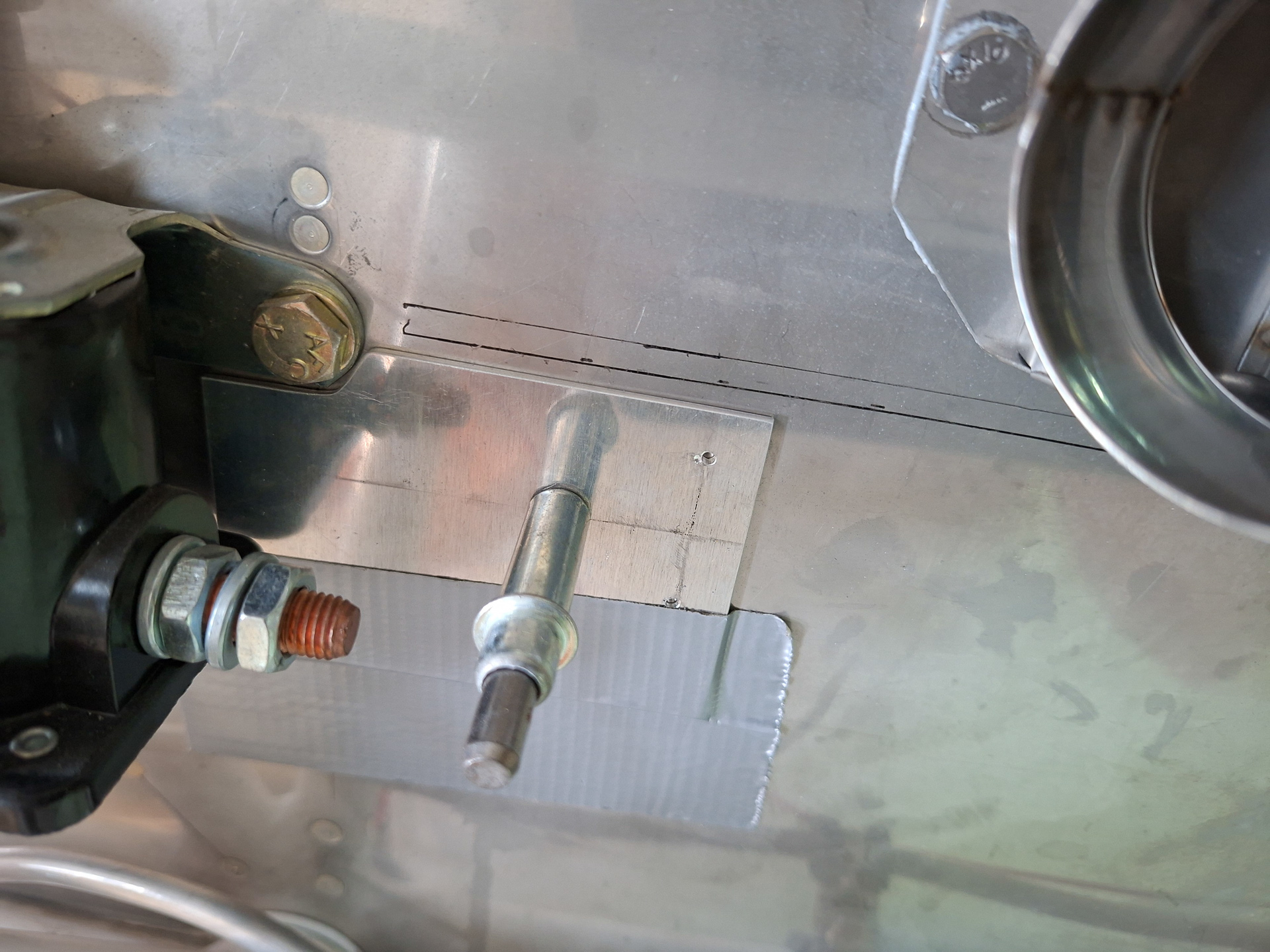
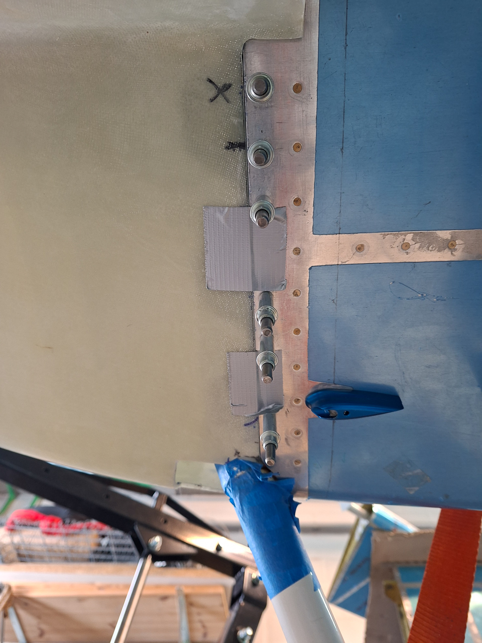
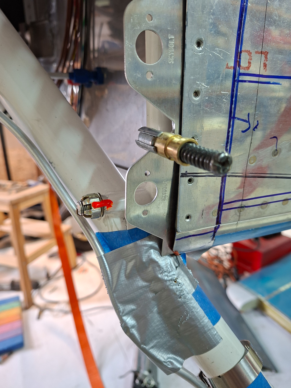
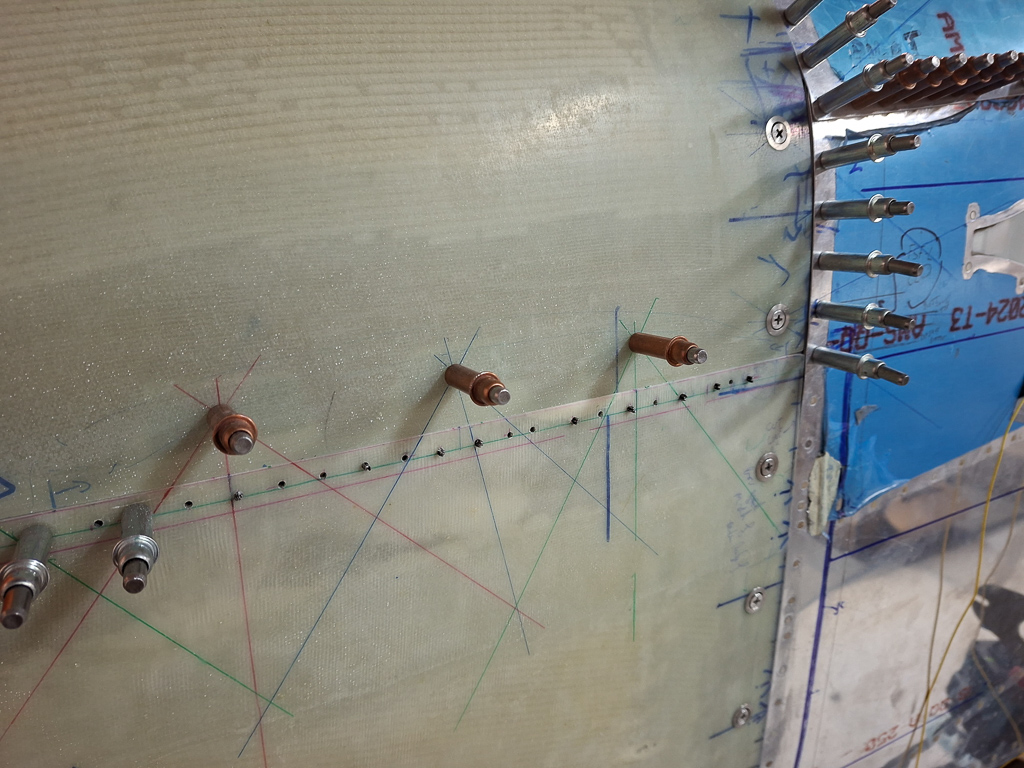
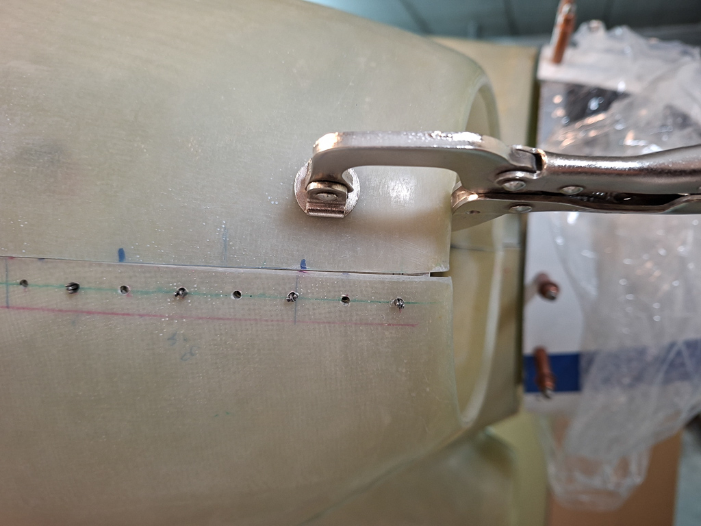
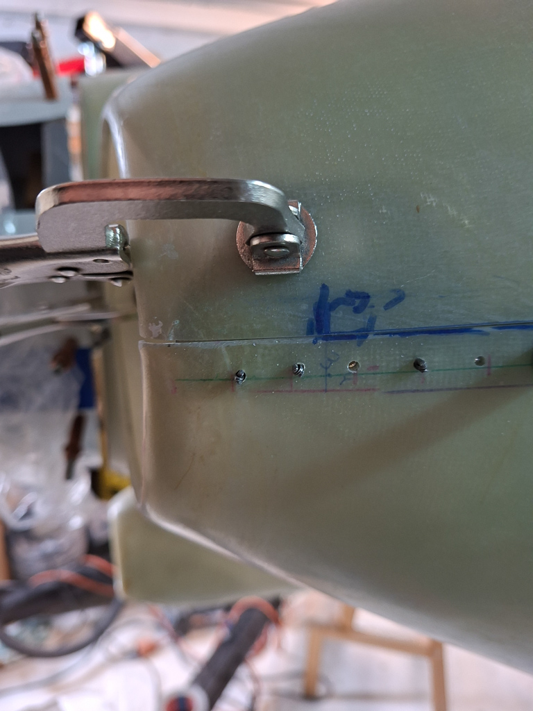
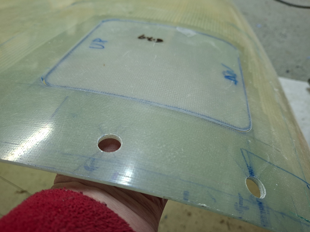
I started by drilling out the rivets from the stiffener and then cut a very rough oversized shape. From this rectangle I first cut out the clearnence for the starter contactor leg. Once the plate would fit, I measured carefully the location of the firewall passthrough for the AN fitting and drilled a pilot hole #40.
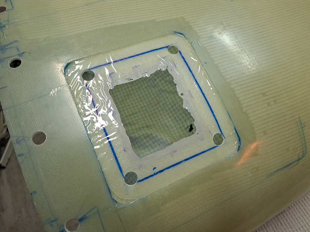
Once the hole was defined, drilled the two right side rivet locations on the fuel doubler plate.
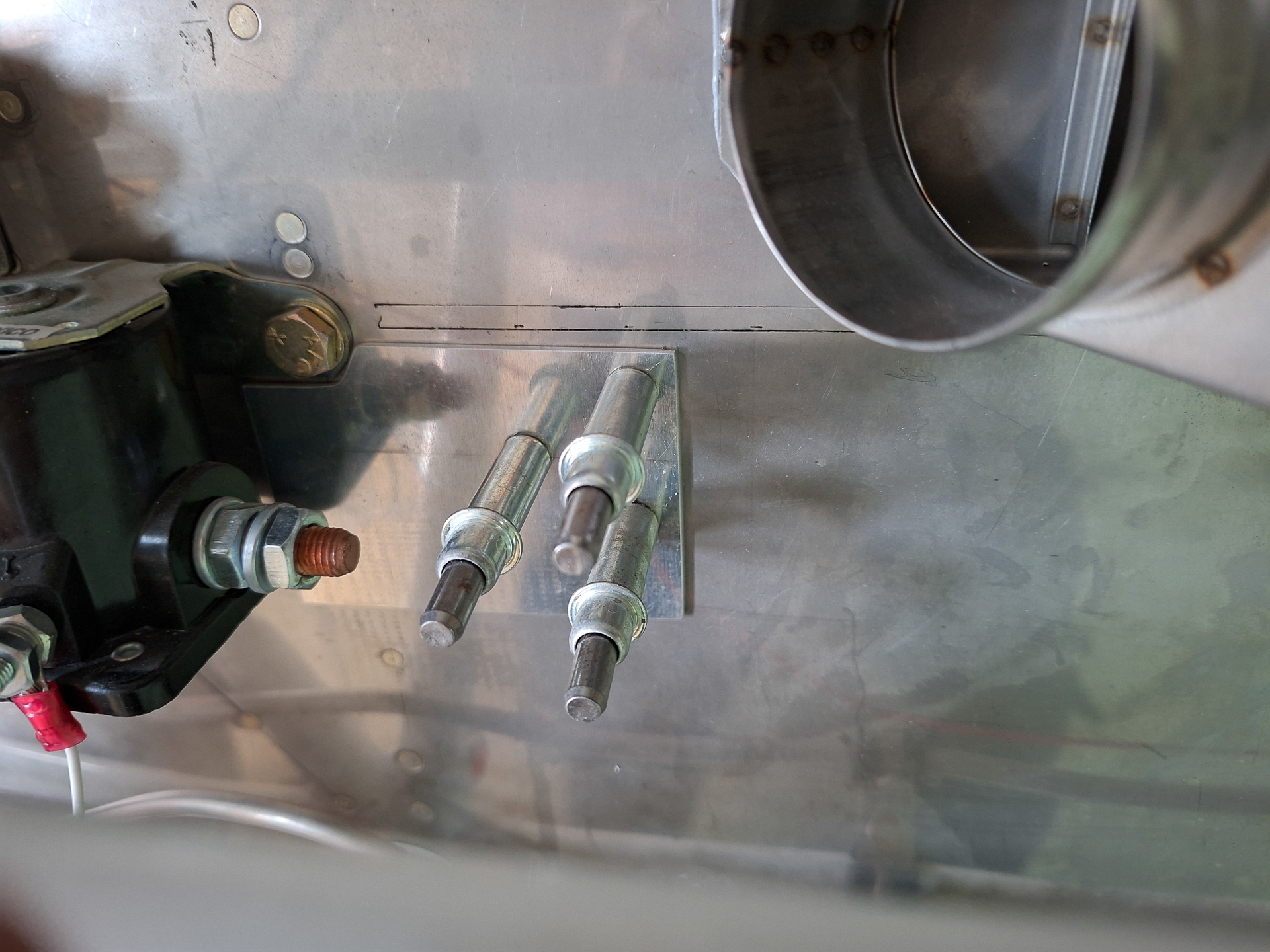
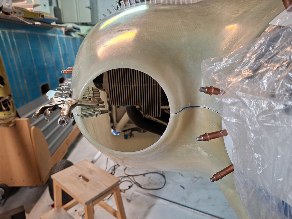
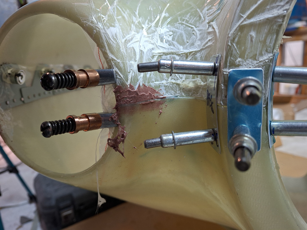
Then needed to drill the other 2 holes in the firewall stiffener. I could back drill one hole from the cockpit side through the existing hole, but the new one was a bigger problem. Ideally I had to drill this from the front side. This is where a lot of additional work surfaced. The contactors are seriously in the way and it's not possible to drill while the start contactor is on. Same issue for rivetting them so it had to come off anyway. Typical airplane building stuff, when you think something is mounted for eternity, it will have to come of two or three more times.
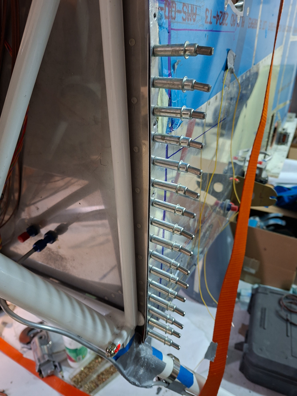
All removed and the 2 holes through the firewall vertical angle drilled.
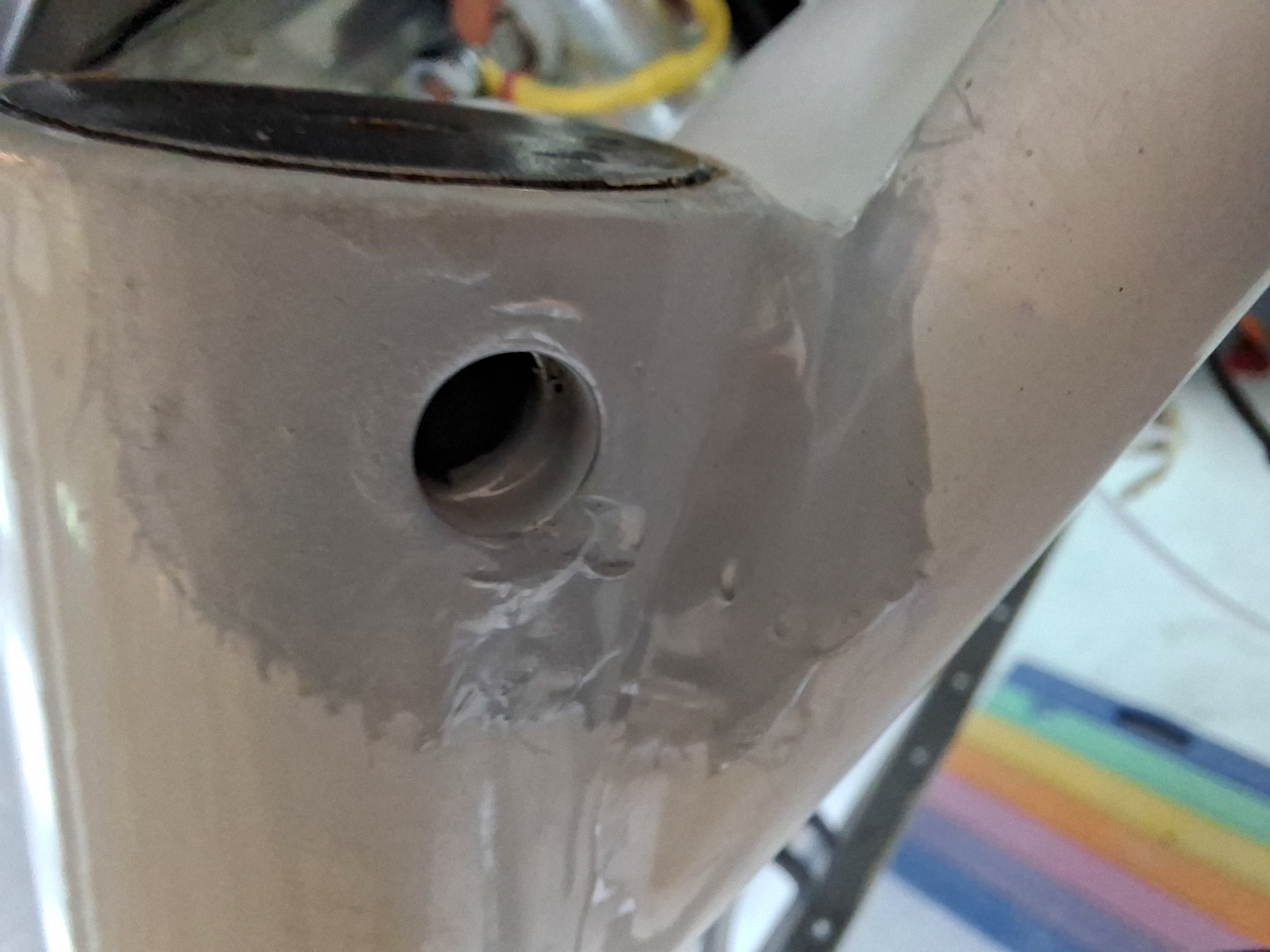
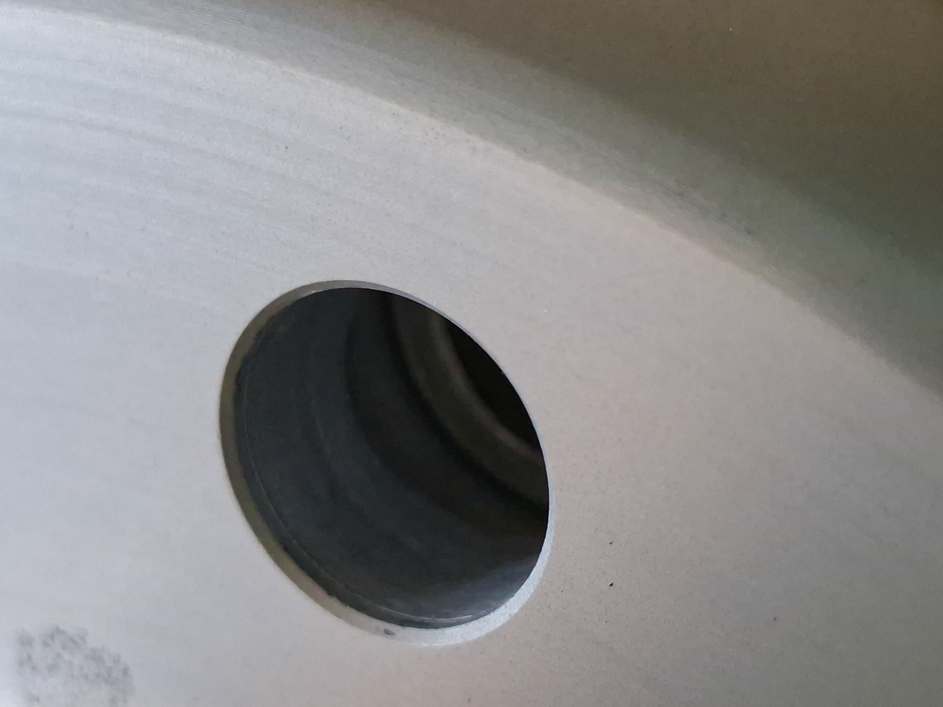
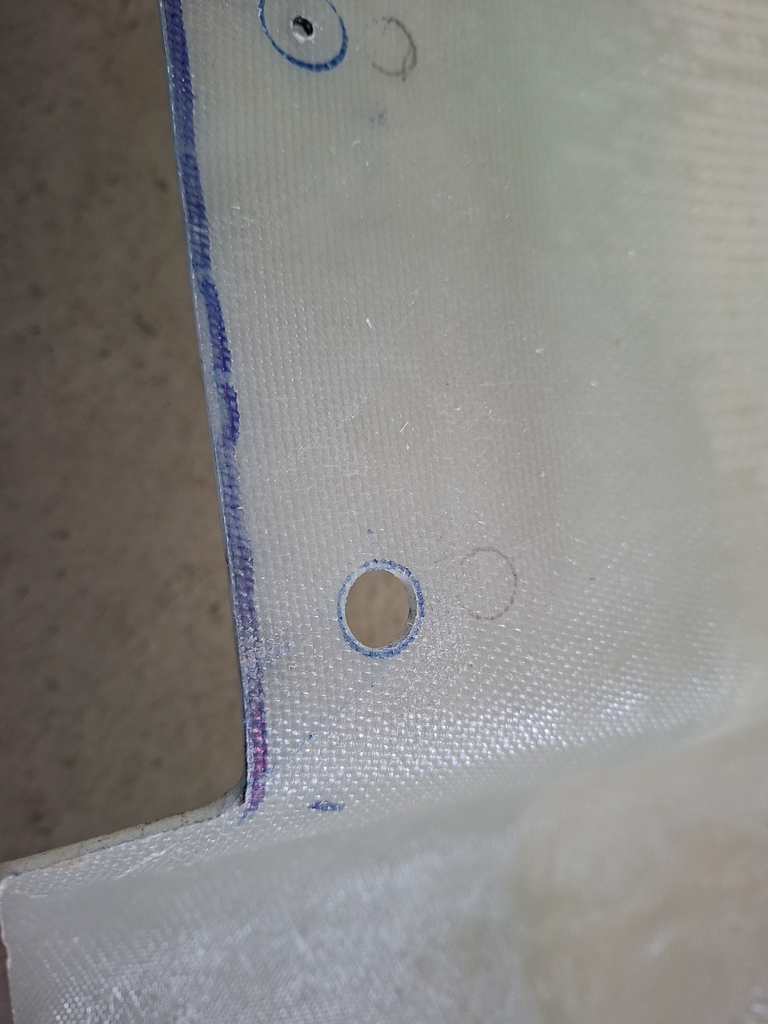
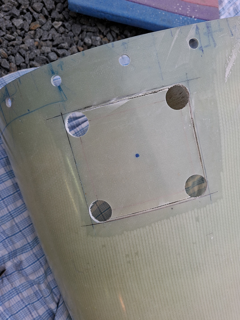
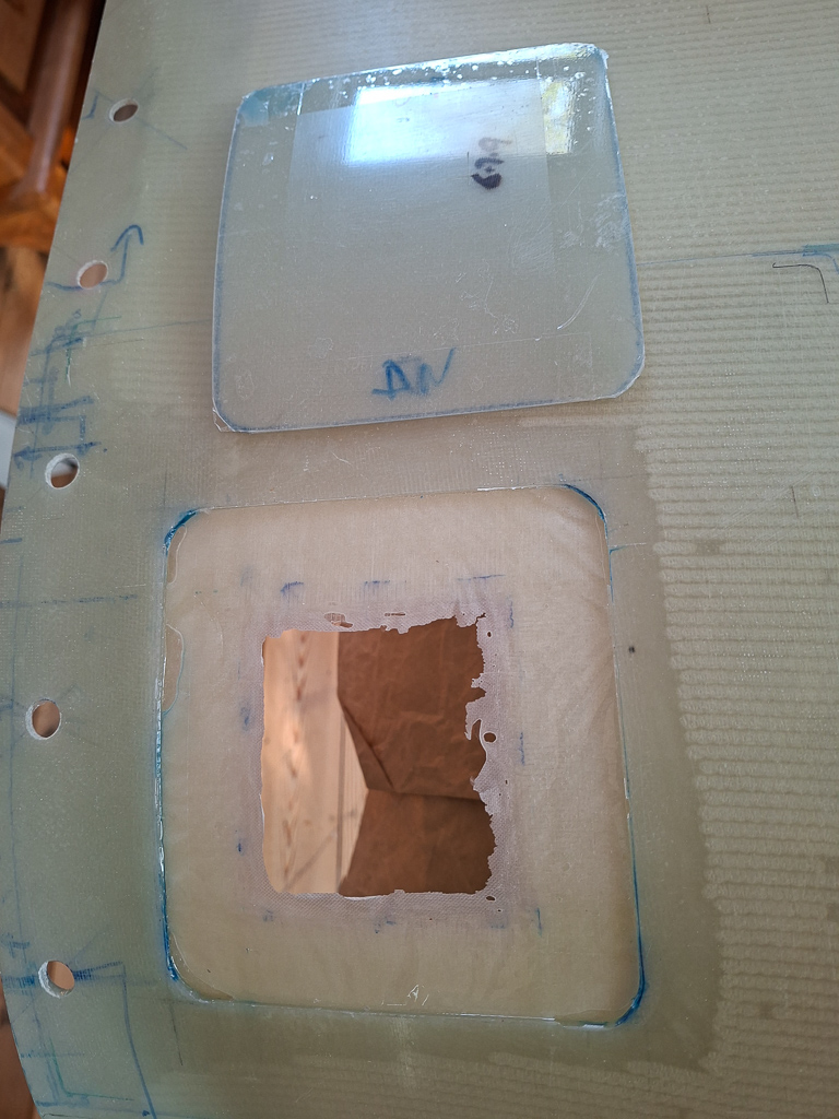
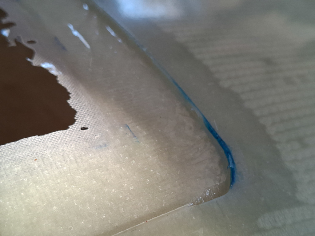
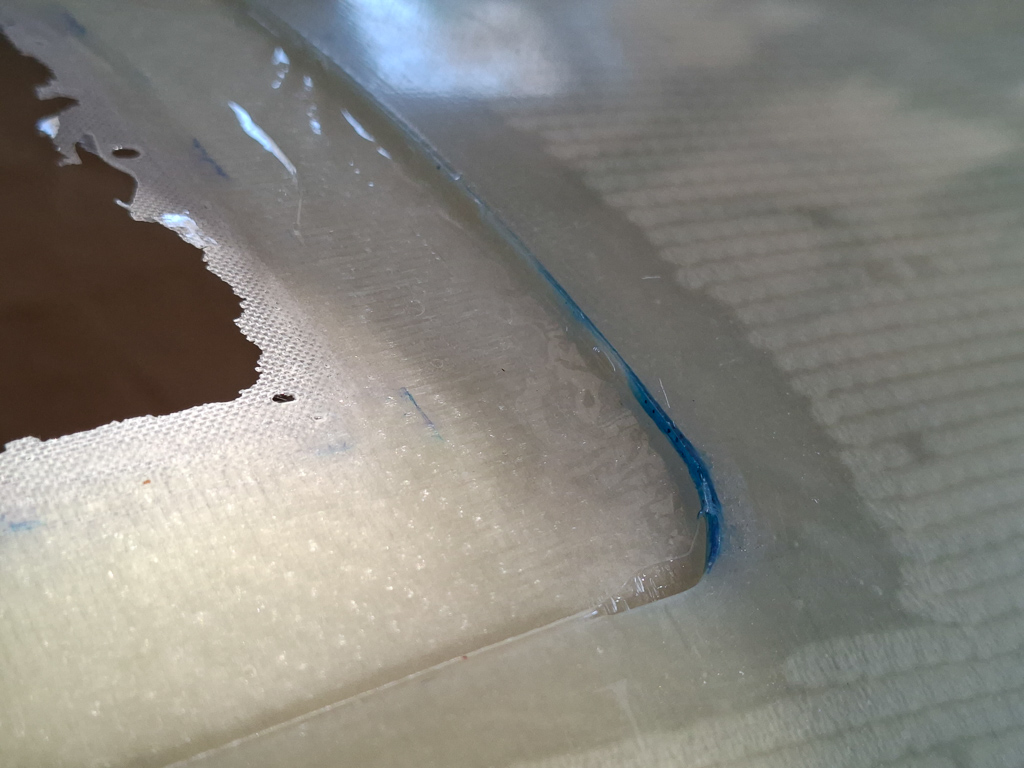
Then I used a rota-cut drill from the inside to upsize the hole for the AN fitting and sanded it to smooth edges. After all, this is your life line.
Then countersunk the holes on the doubler. The doubler stays on the front side as it won't fit from the back due to the firewall stiffener angle. Next I drilled 2 additional holes next to the stiffener for extra strength.
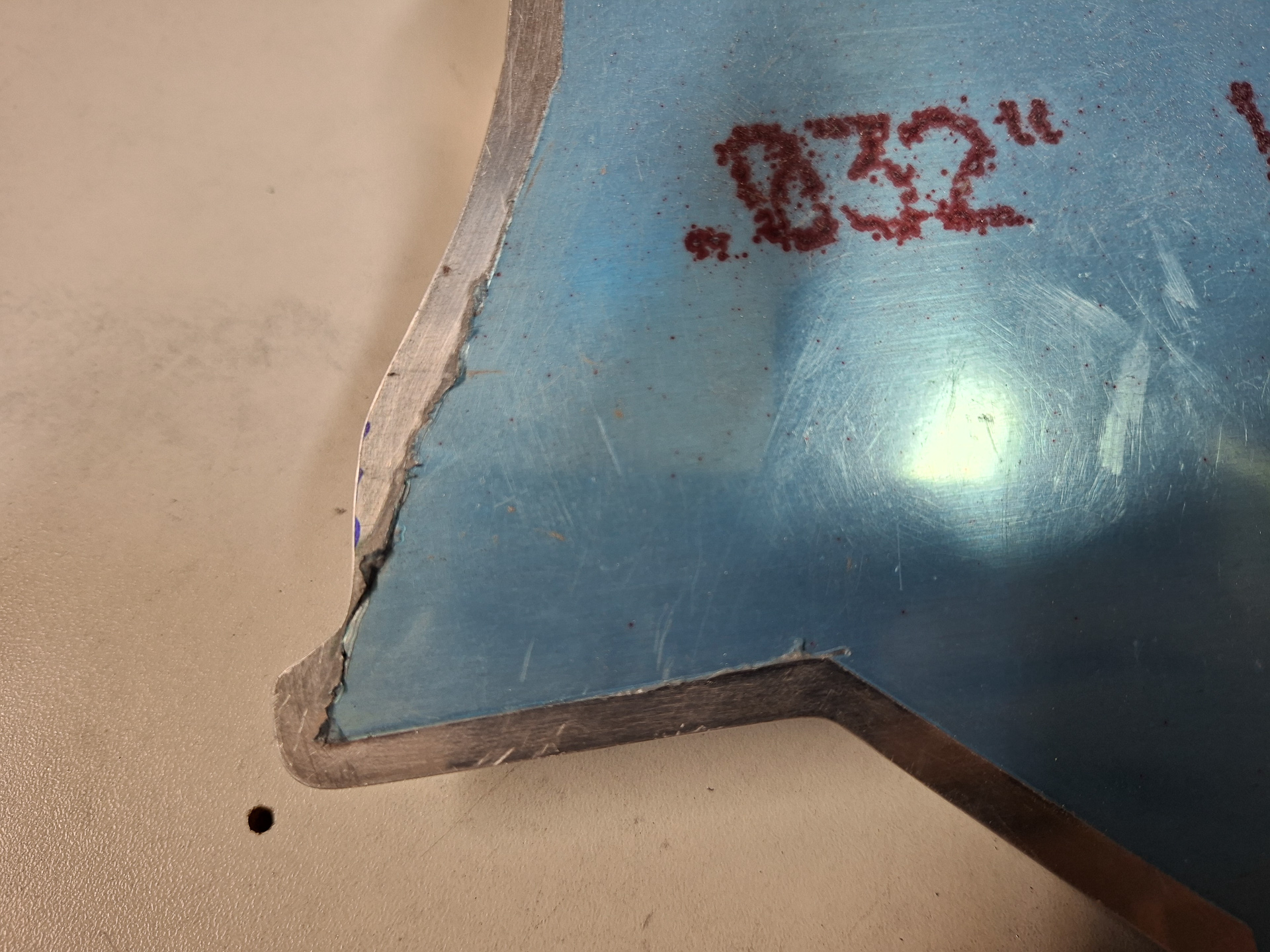
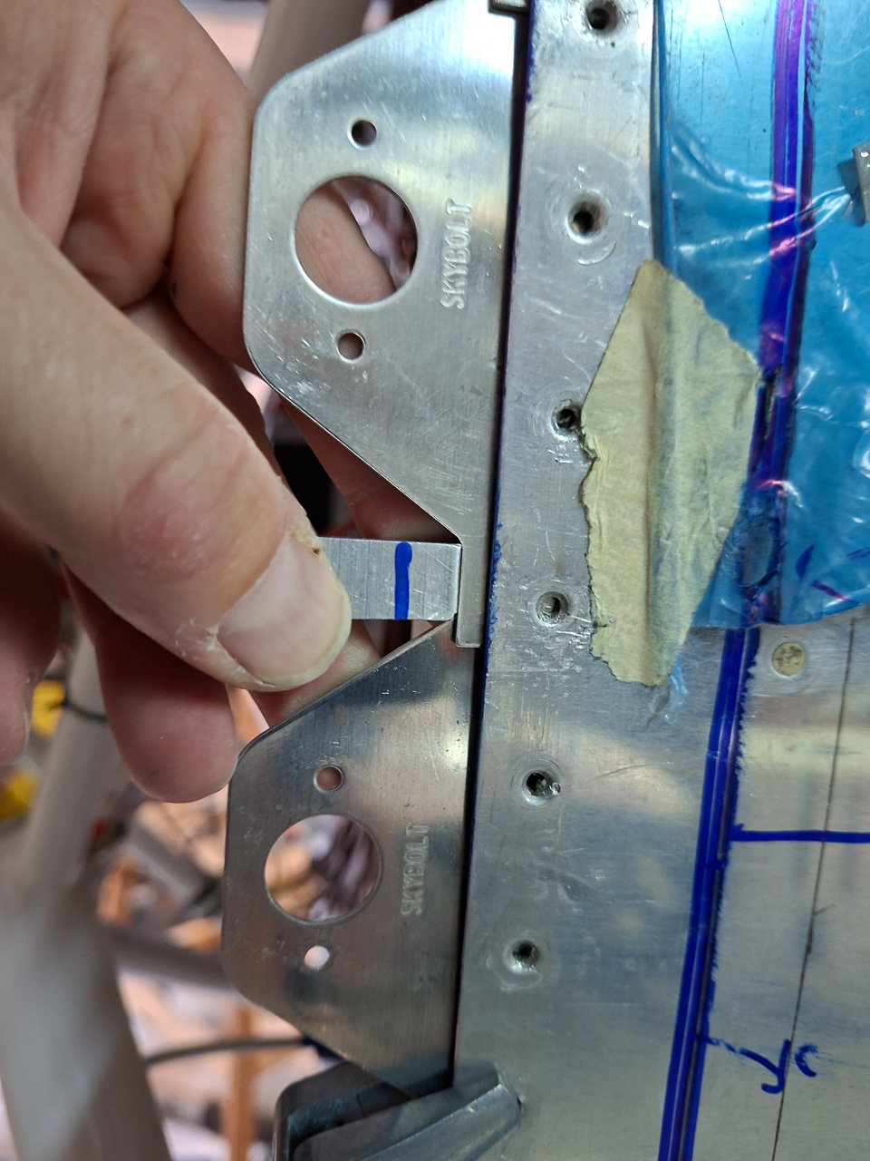
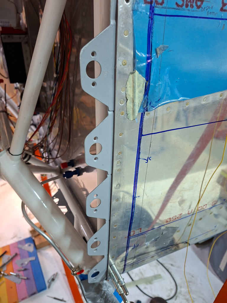
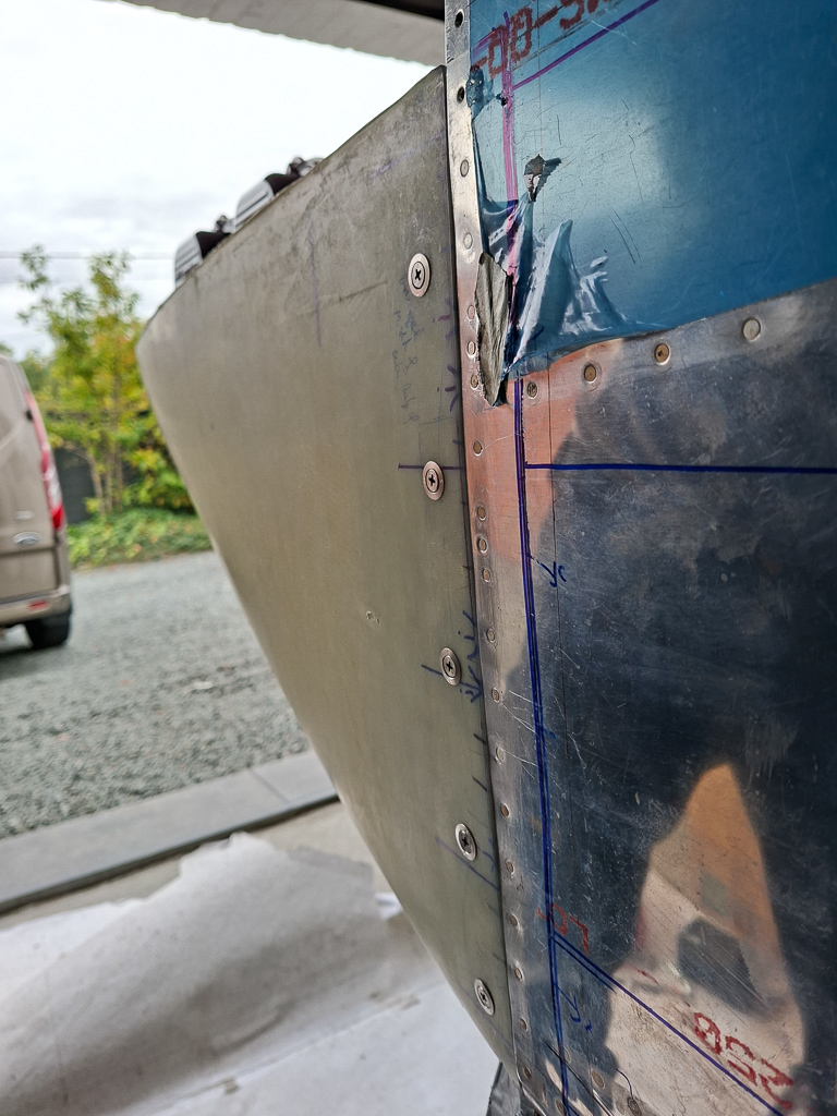
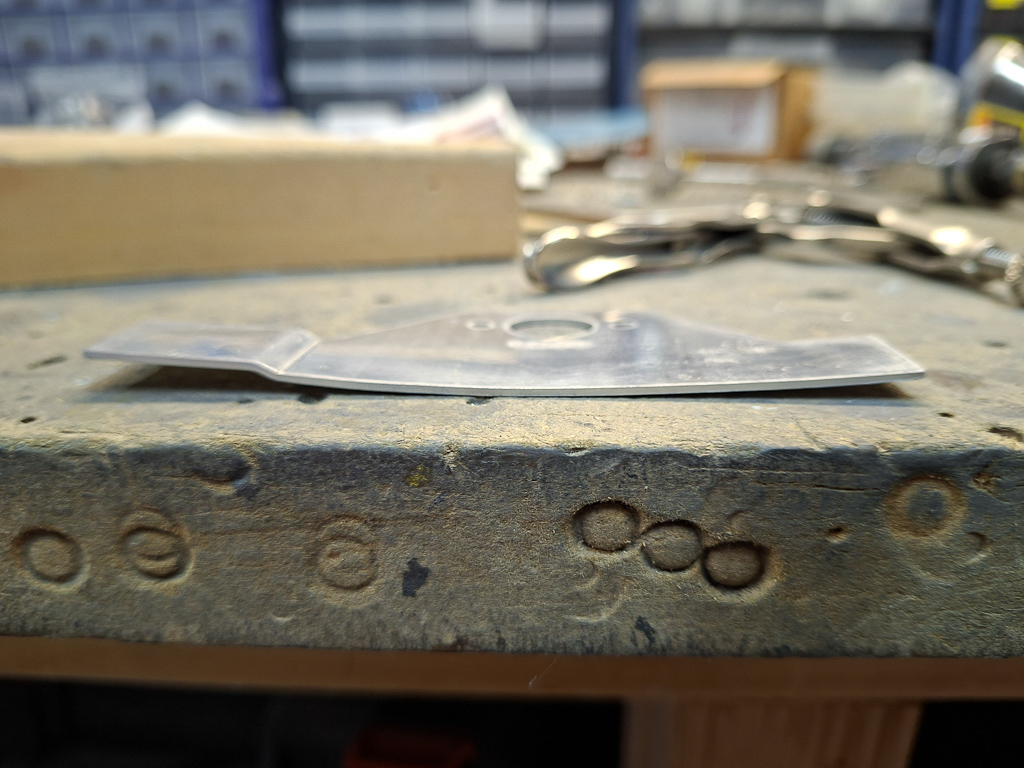
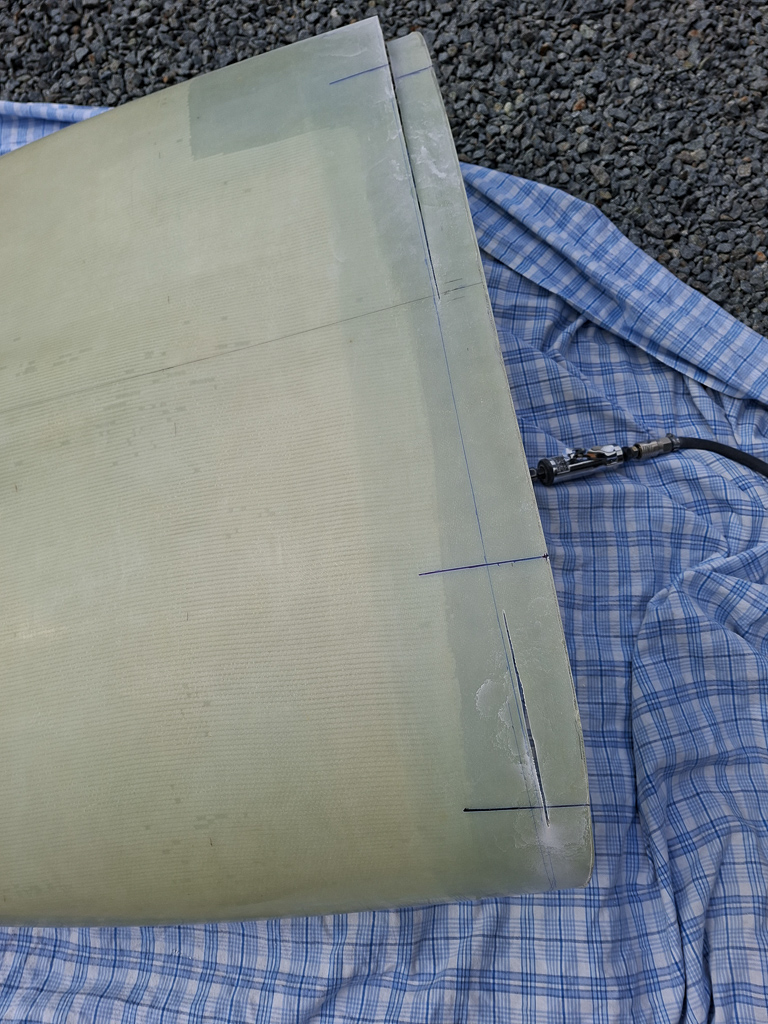
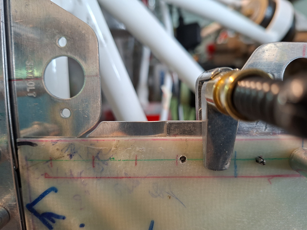
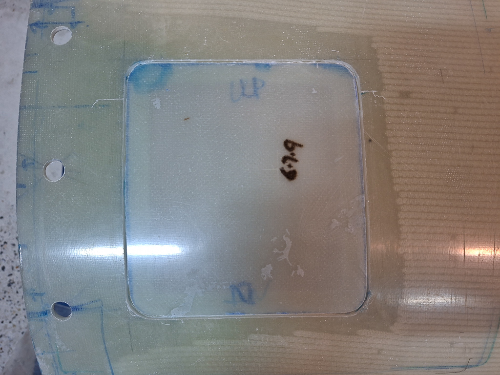
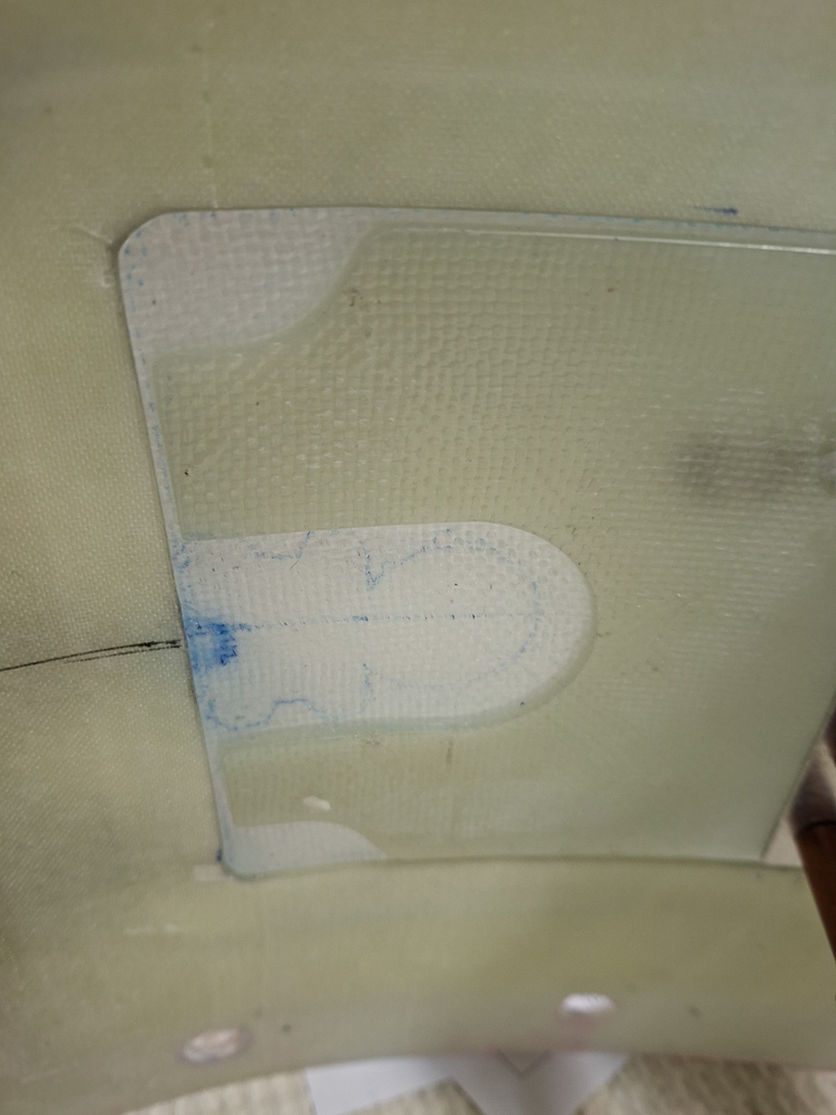
Then finally, I started grinding and reducing the size from the sides to match the dimensions of the plans. The funky tab on the left side makes the doubler a bit larger than according to the plan
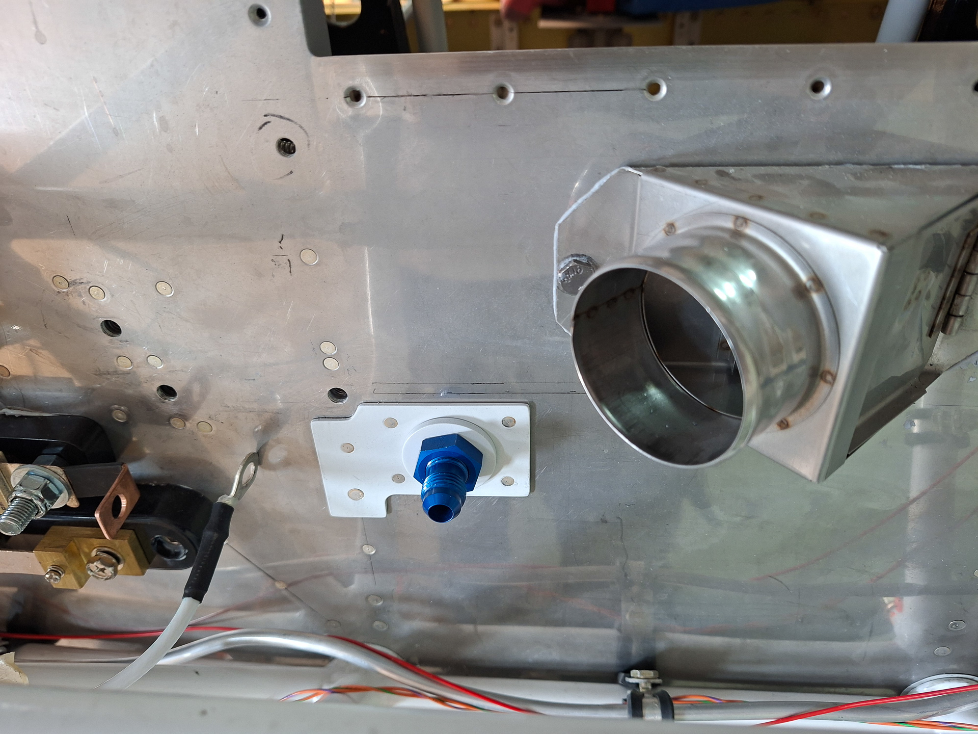
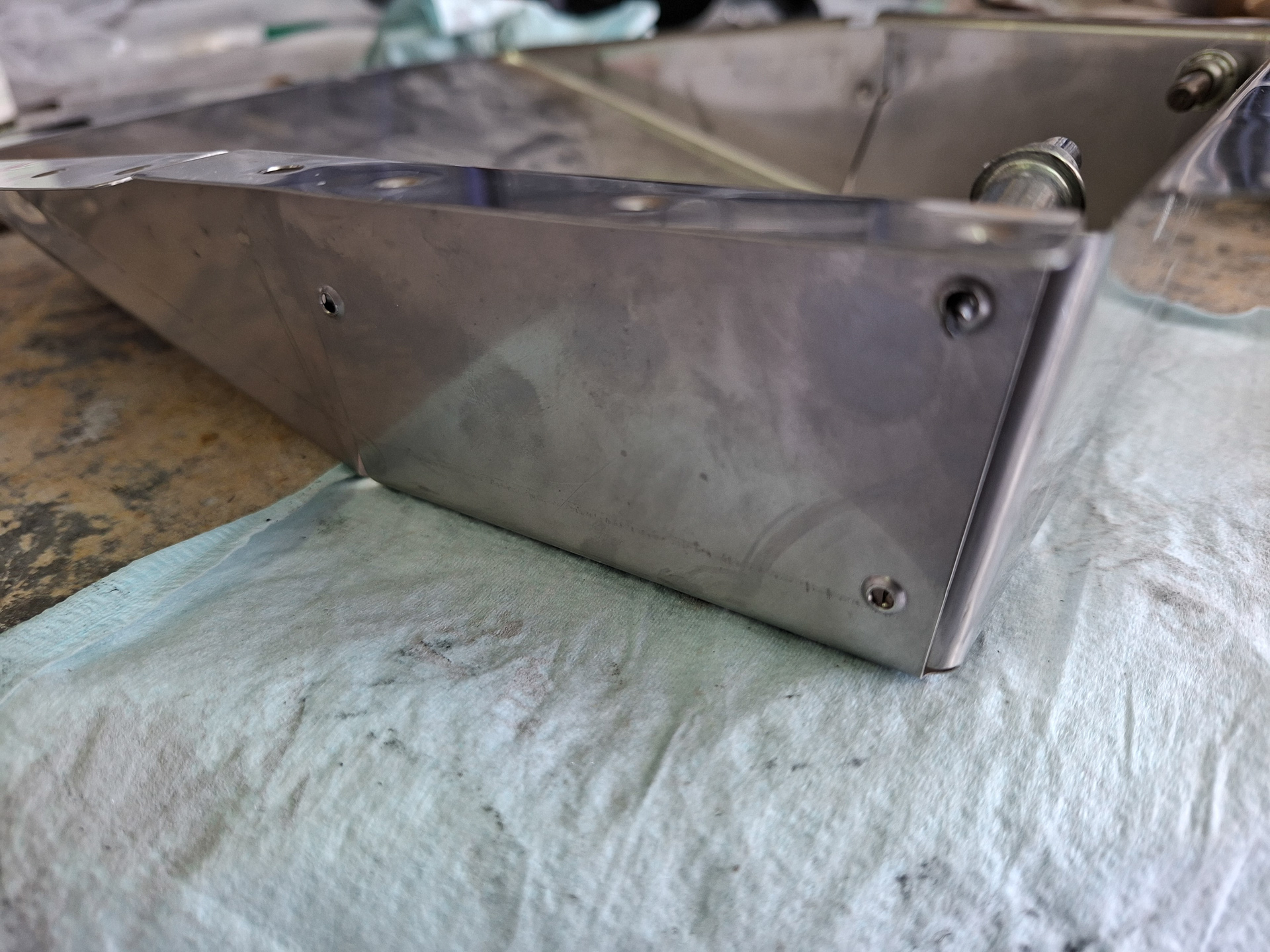
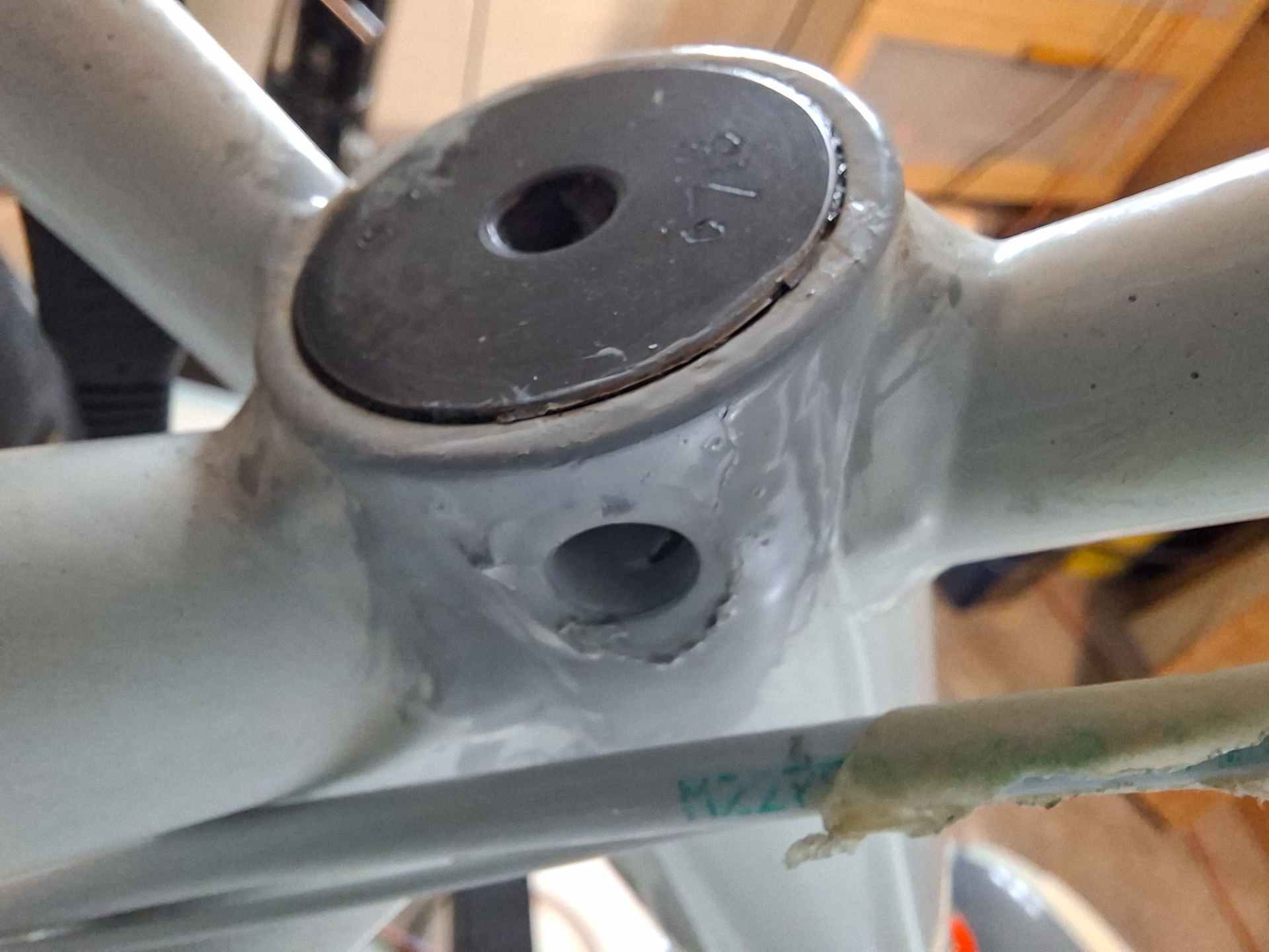
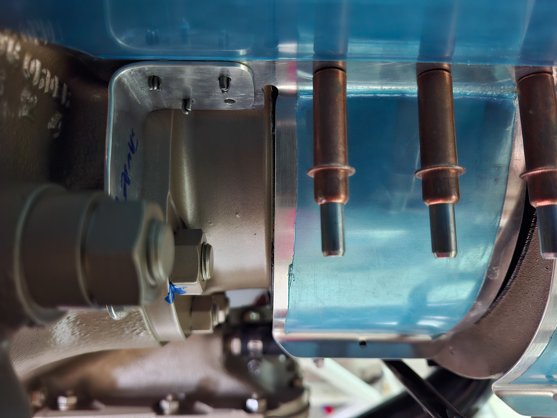
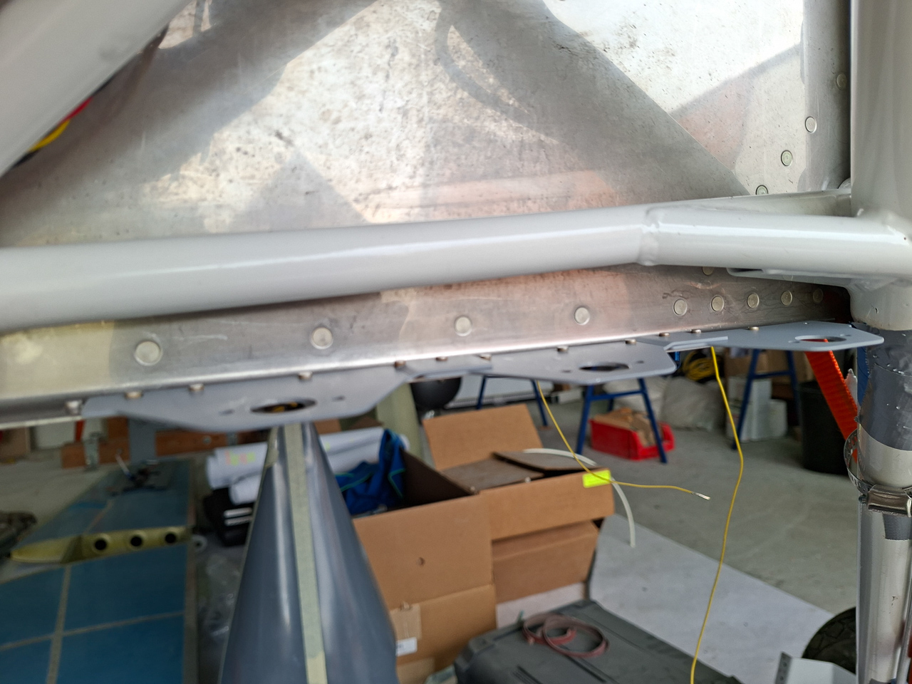
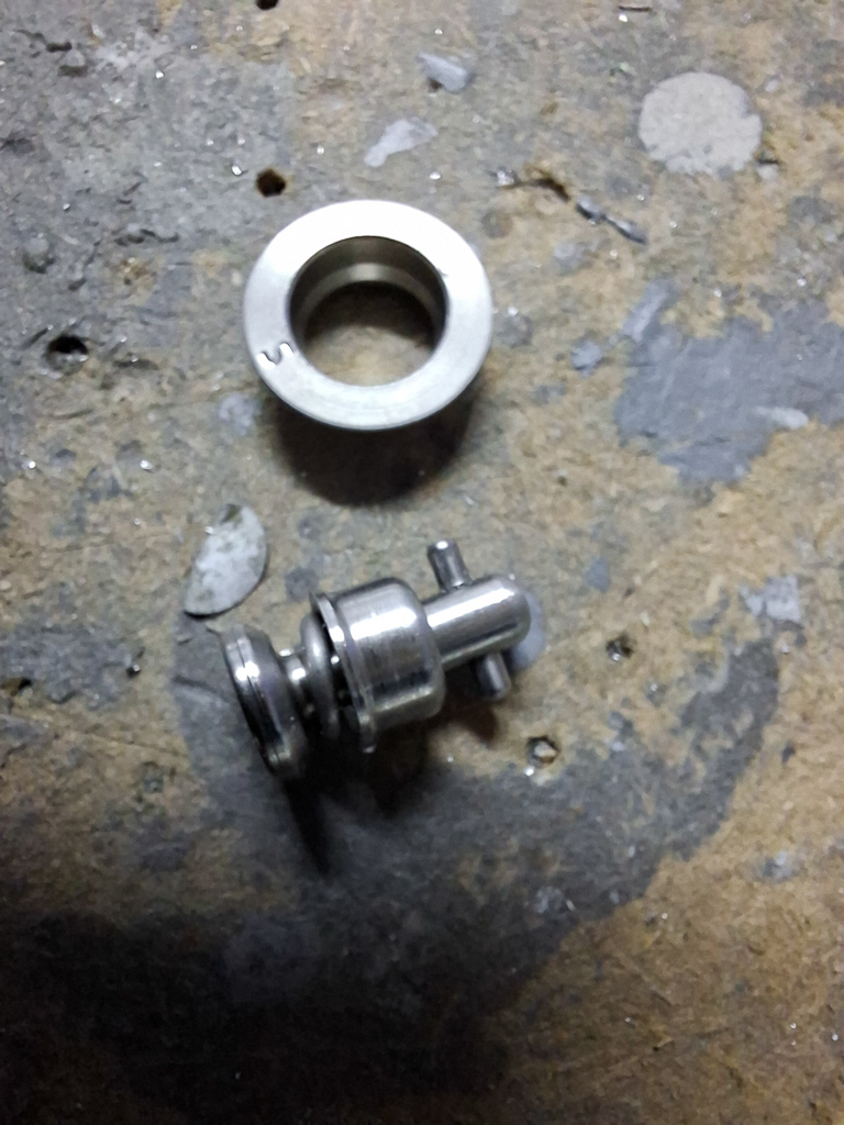
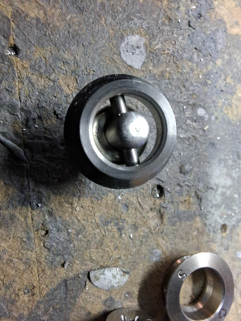
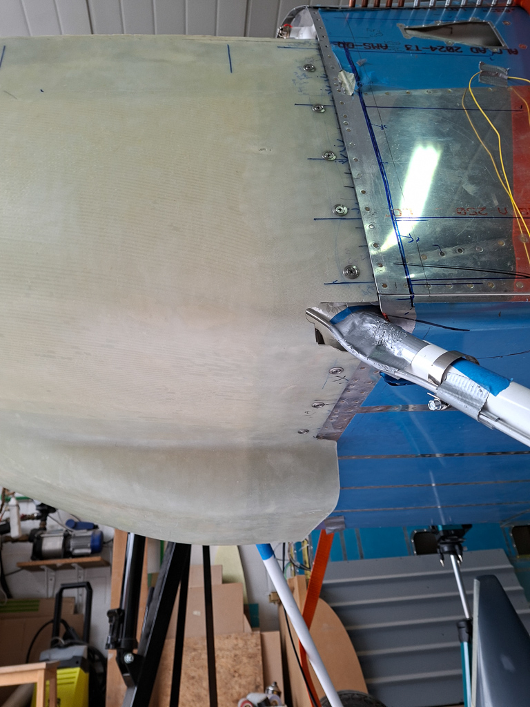
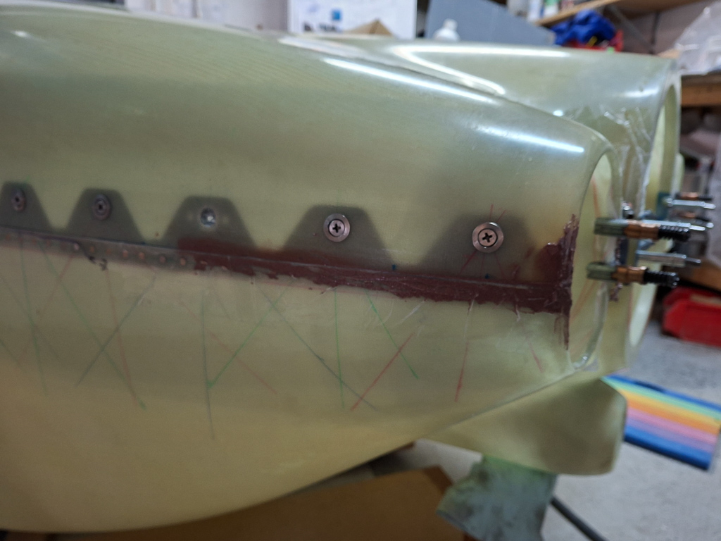
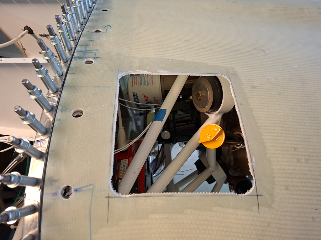
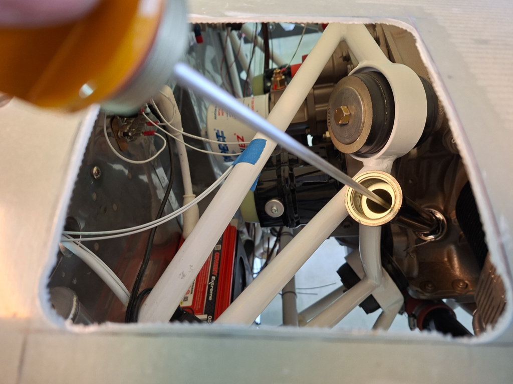
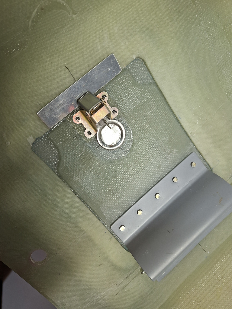
After priming the fuel doubler plate, I could now install it to the firewall using 6 AN426AD3 rivets. Then the AN fitting was inserted, a 6D spacer went over and thightened the AN nut. Looks neat and clean
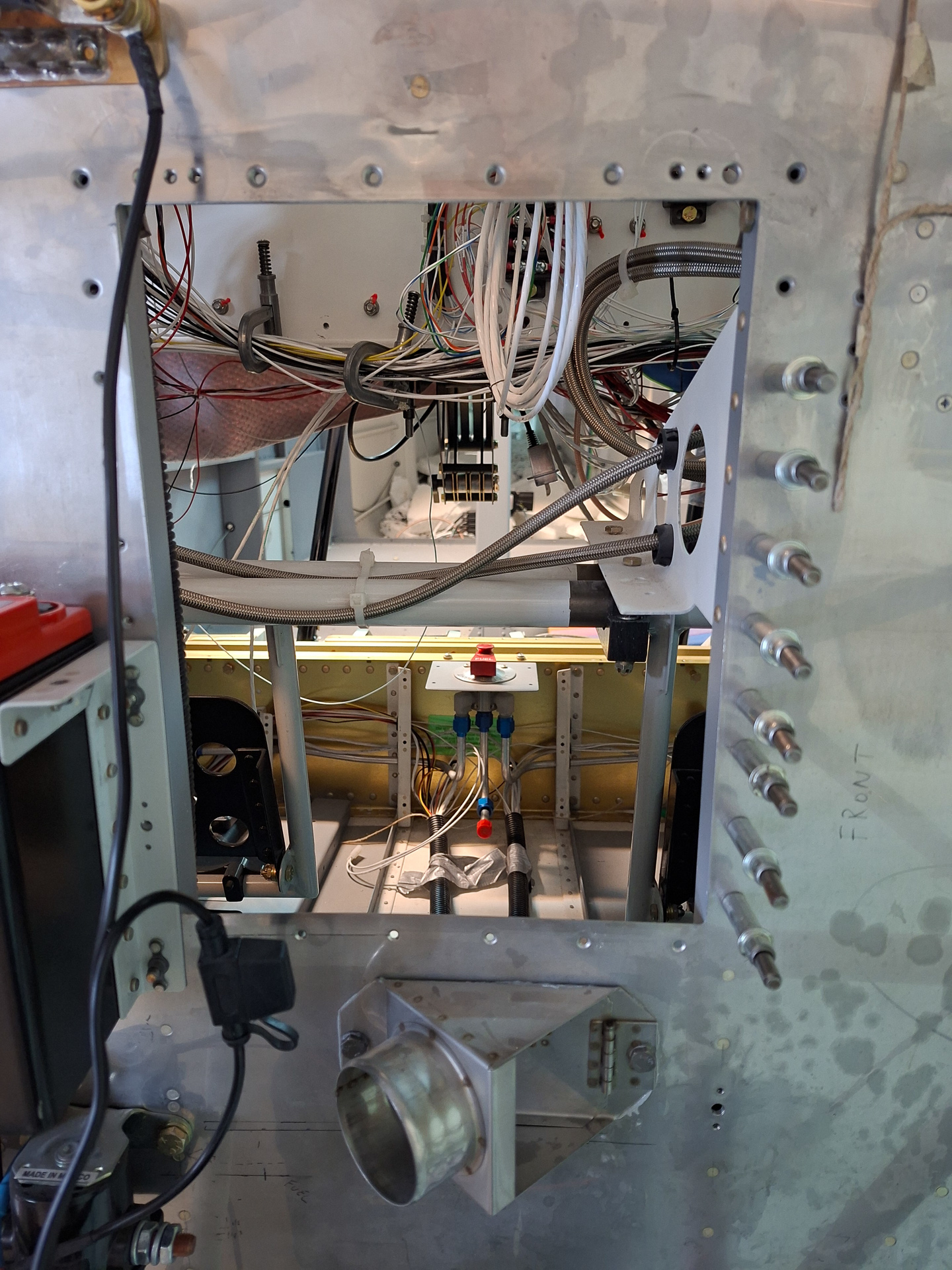
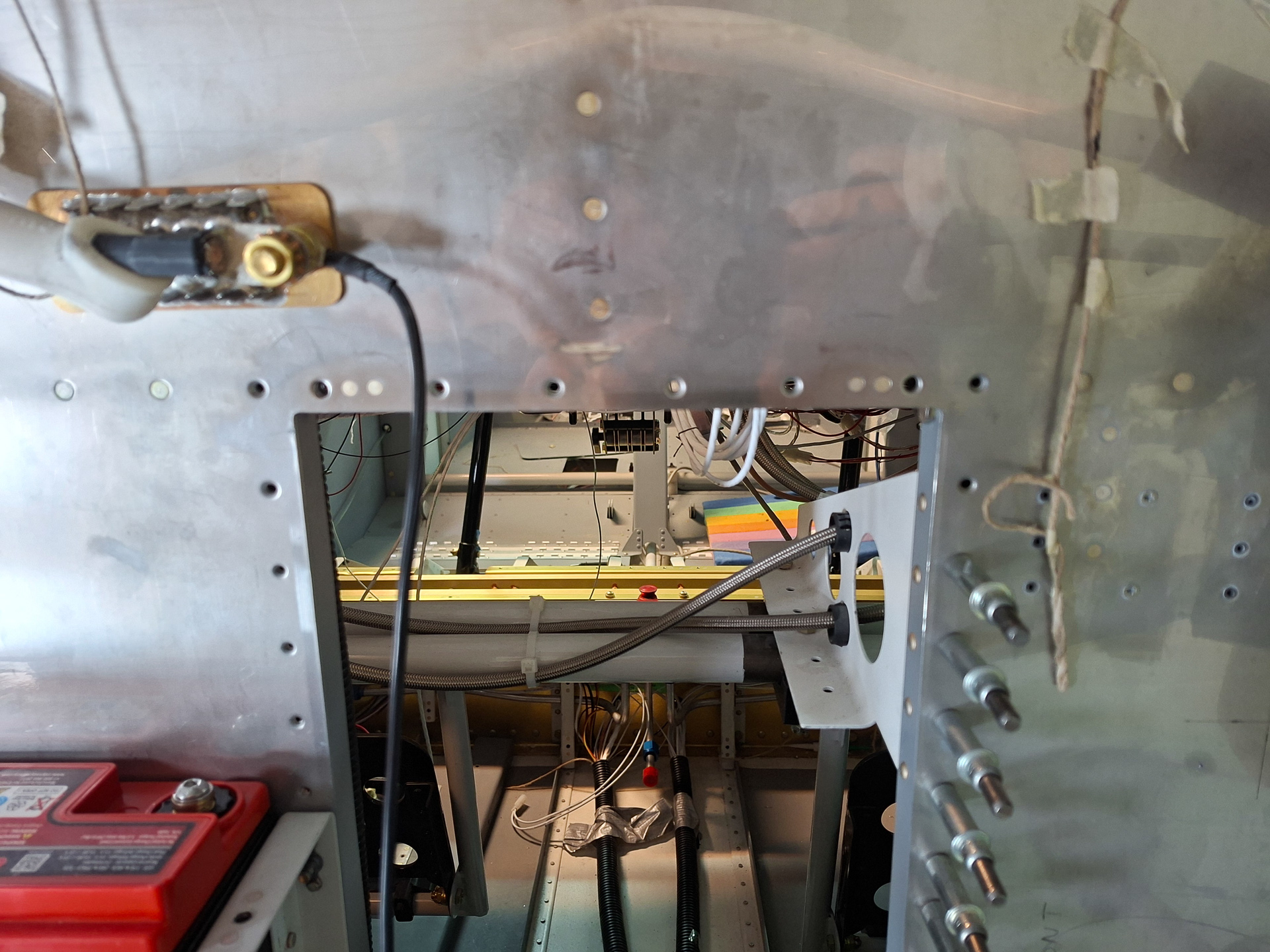
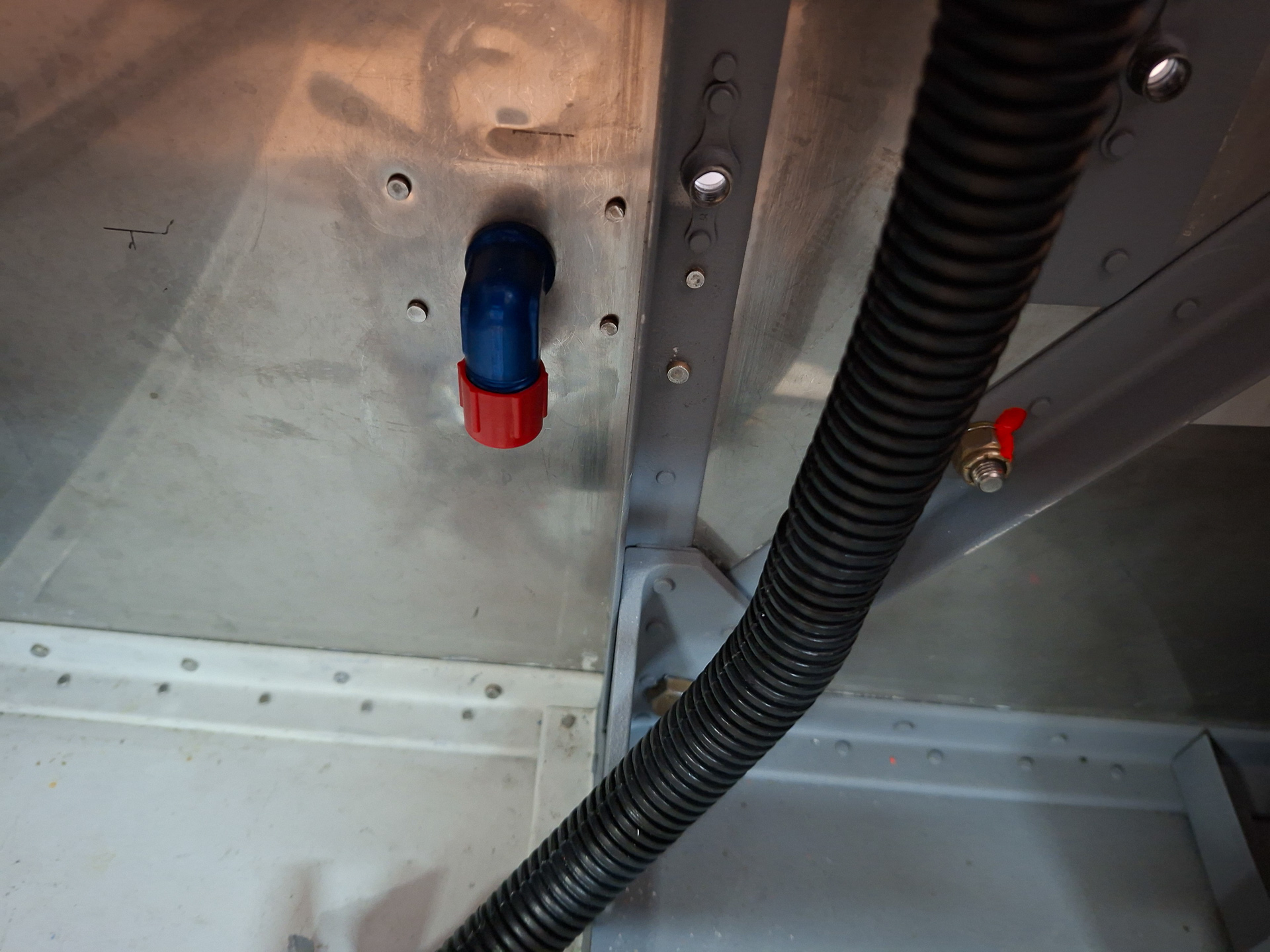
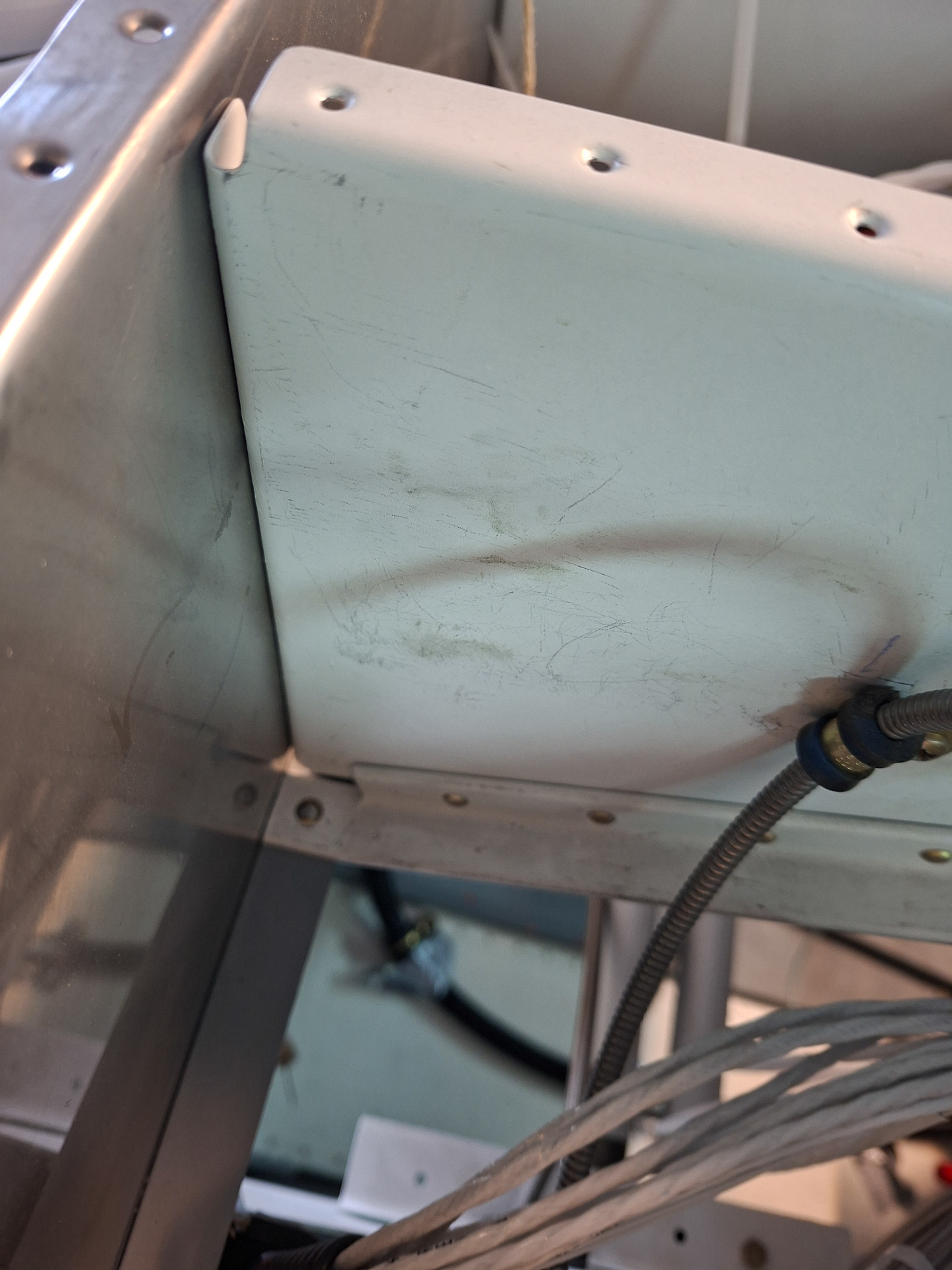
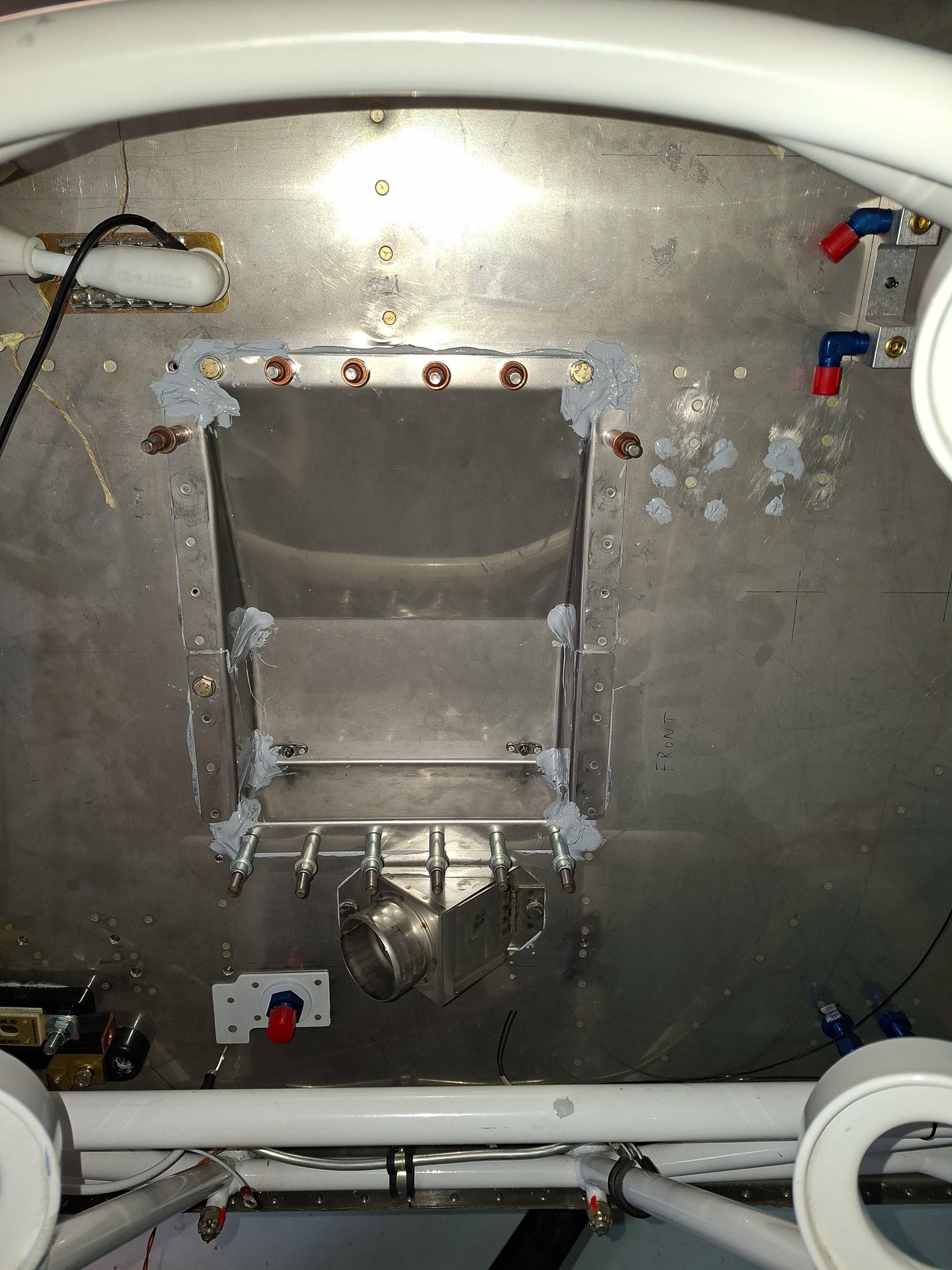
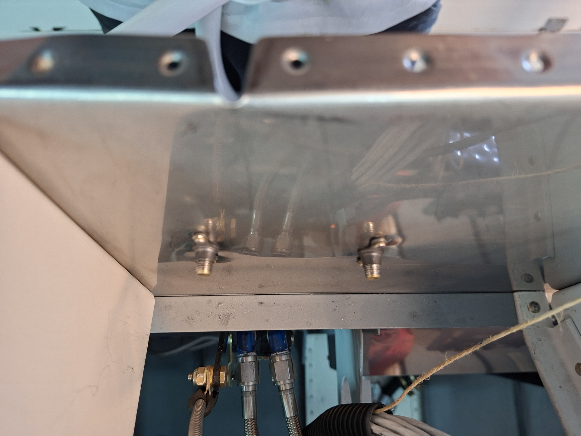
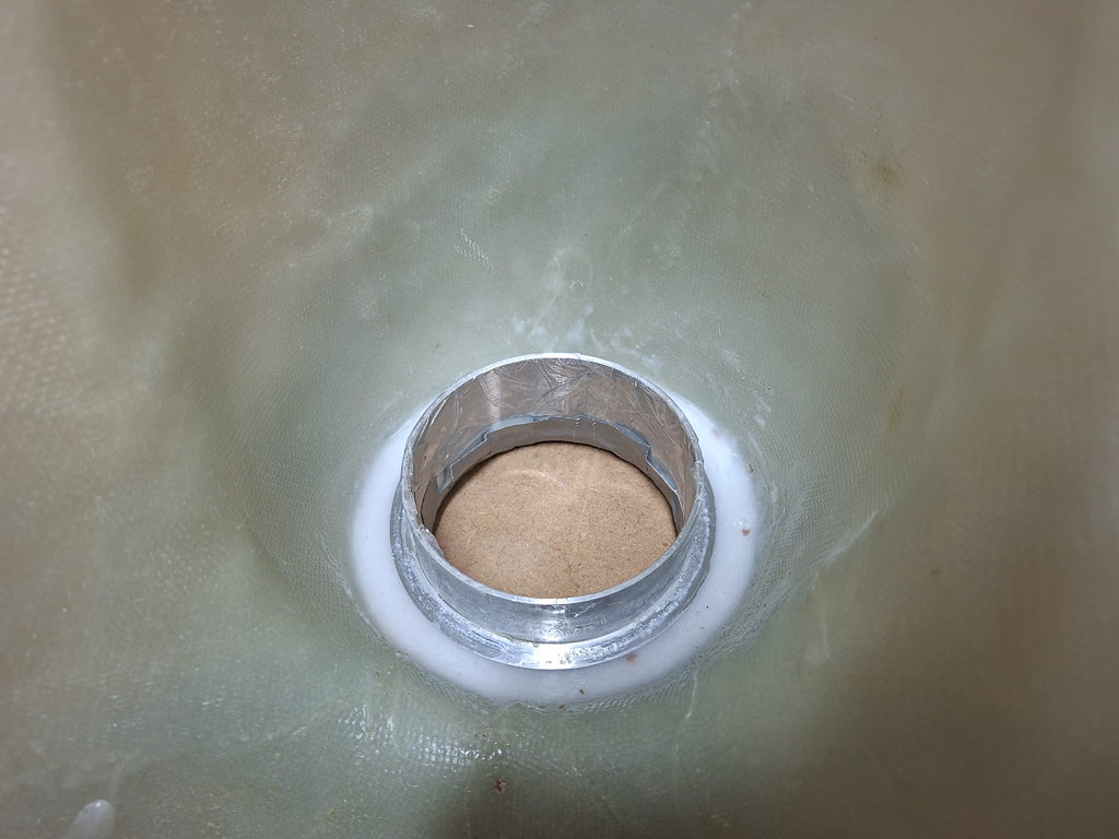
Here is a view from the inside. Fuel will come straight up from here underneath the center cabin cover from the output of the Andair boost fuel pump.
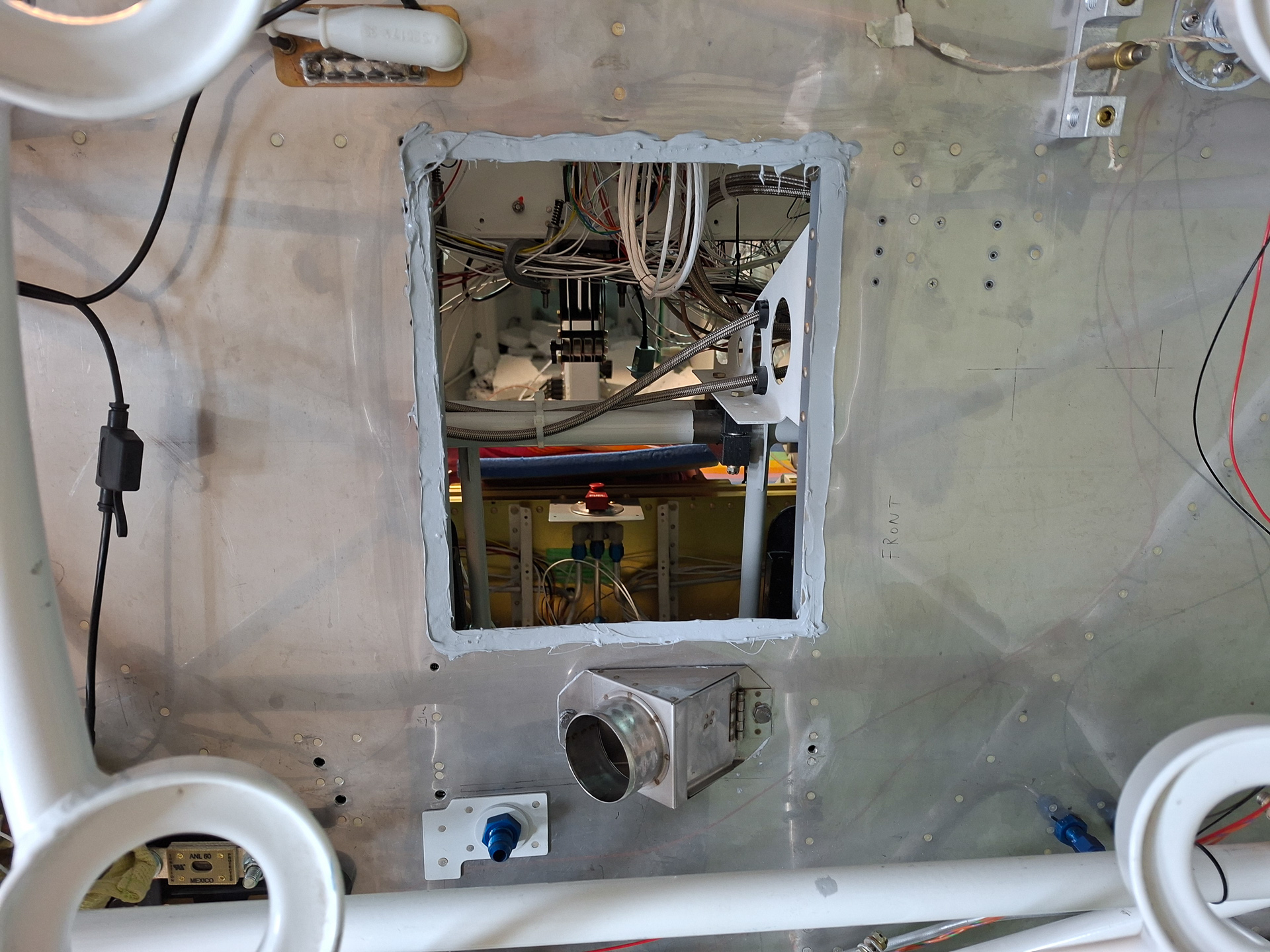
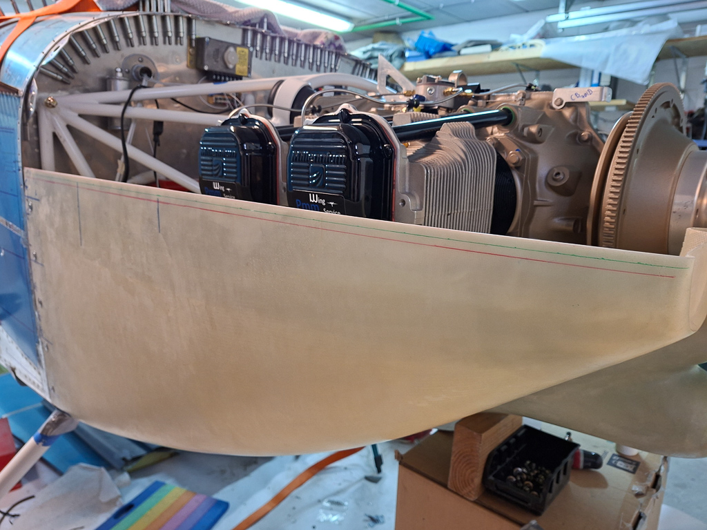
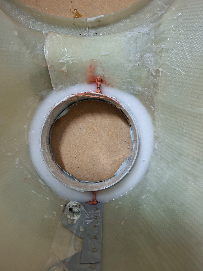
Next I prepared the firewall recess for final installation. It took me a while to decide for final installation as things become much less accessible once the firewall recess is on. I'm committed on hanging the engine soon so it has to be closed anyway.
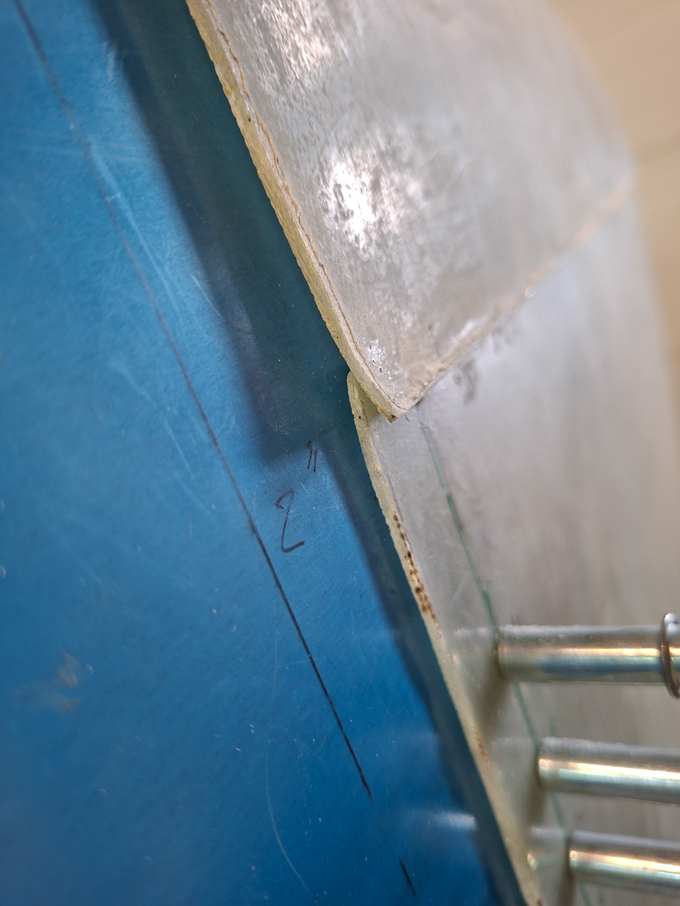
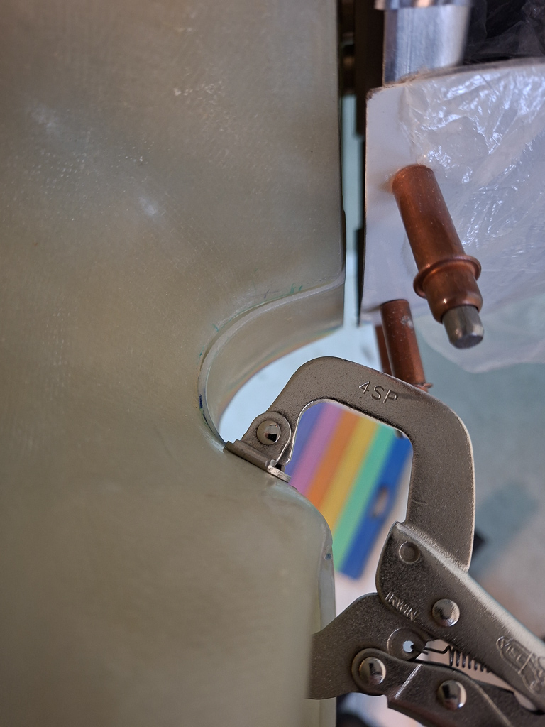
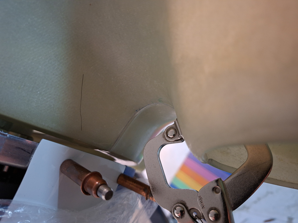
The initial fit showed I had to do some bending and reshaping on the tabs as the leave a gap.
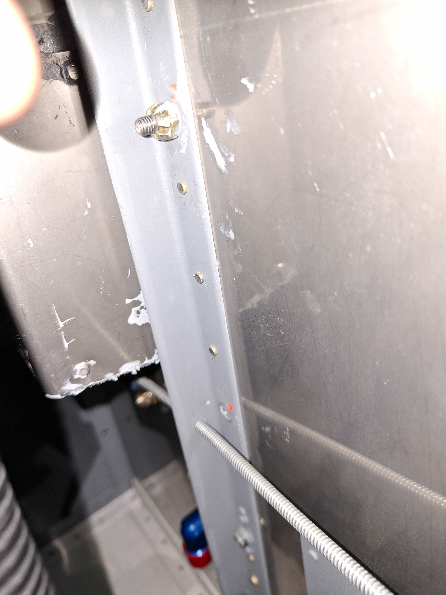
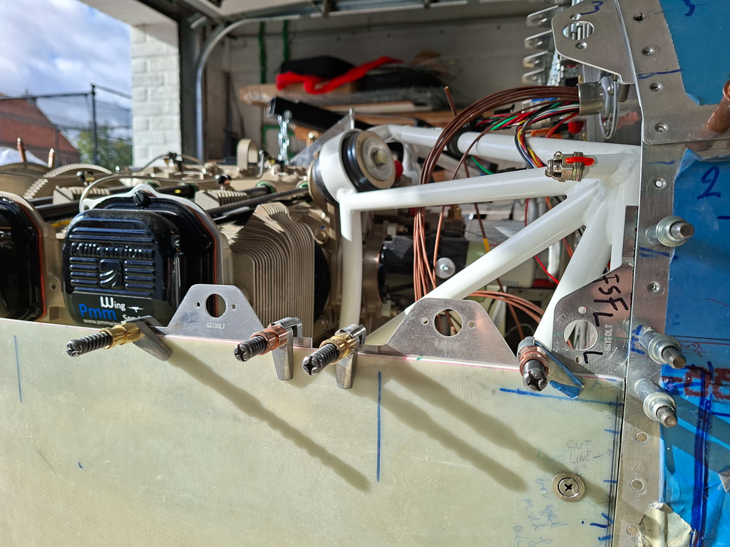
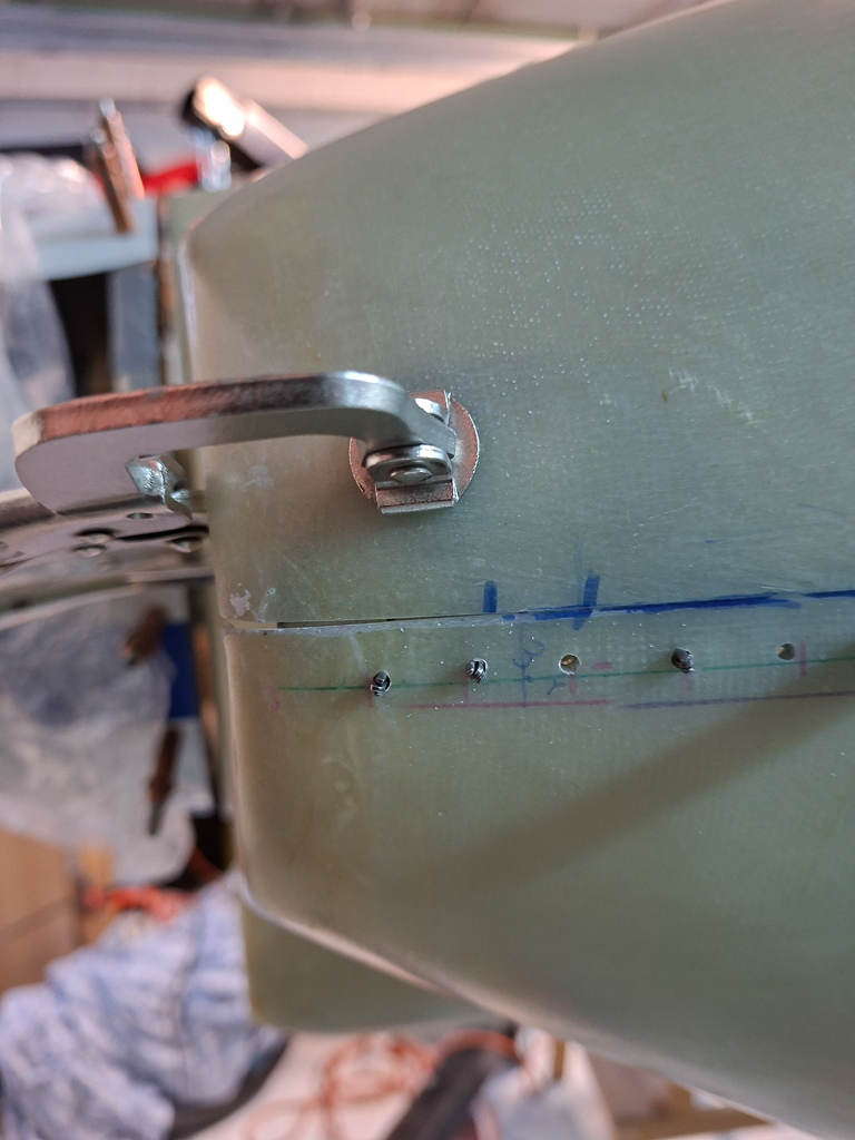
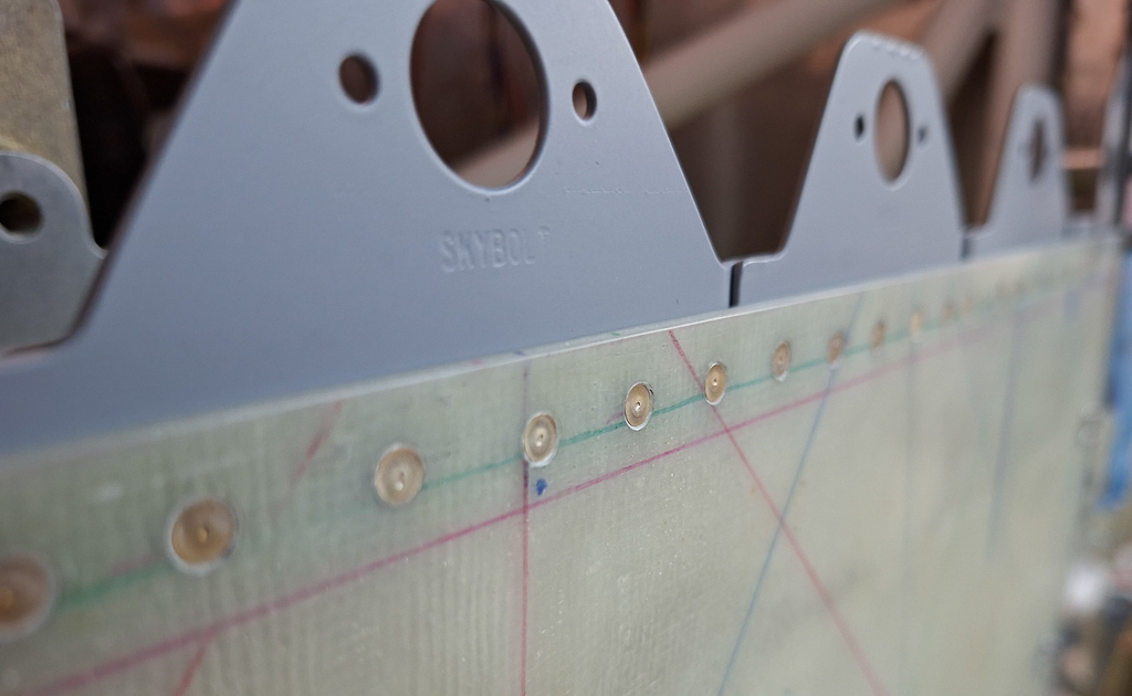
Then noticed the 3 rivets that should first be placed on the side of the recess. 2 on the bottom and one in the middle. Drilled and dimpled the sides and then squeezed 3 rivets in.
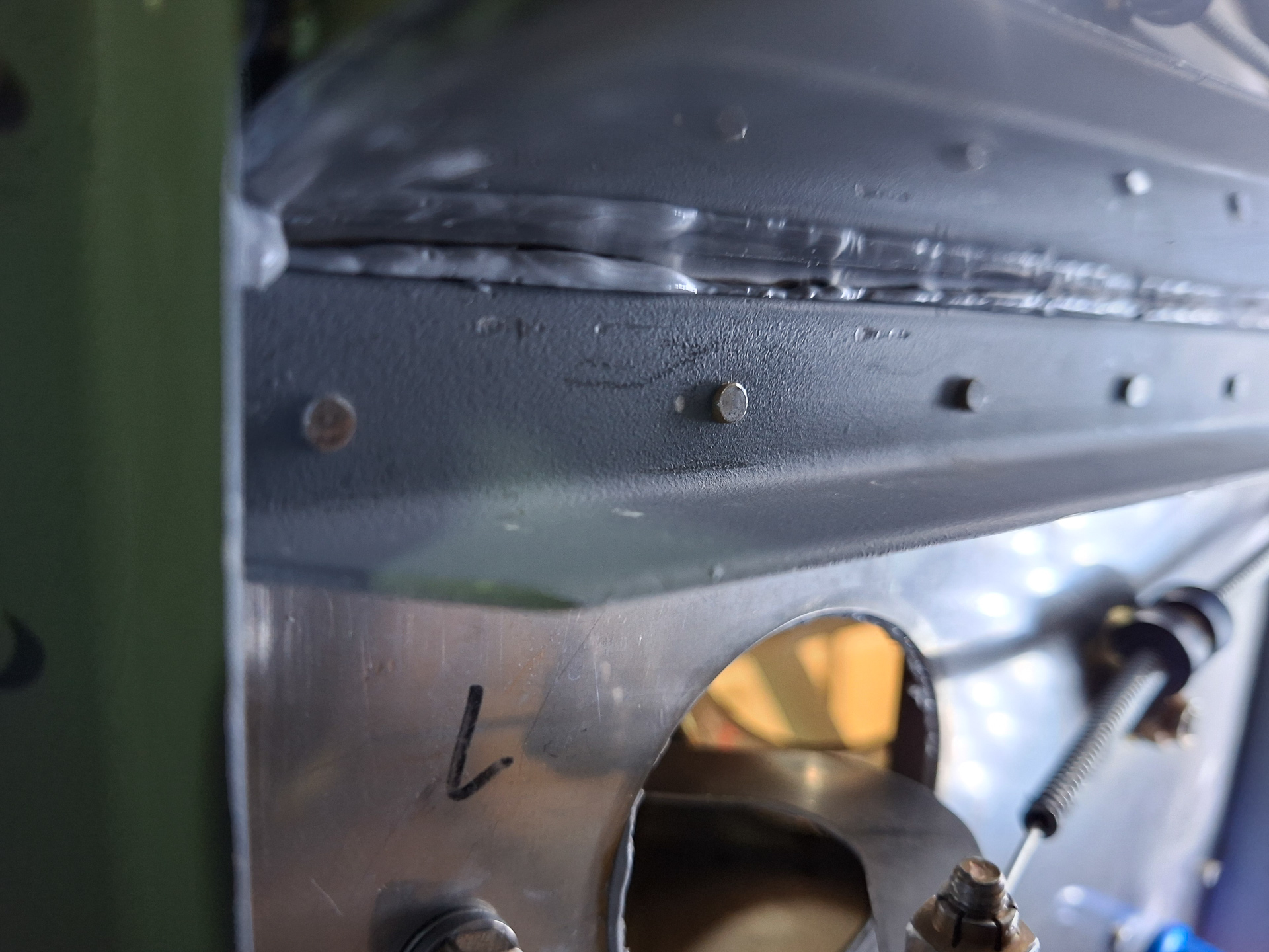
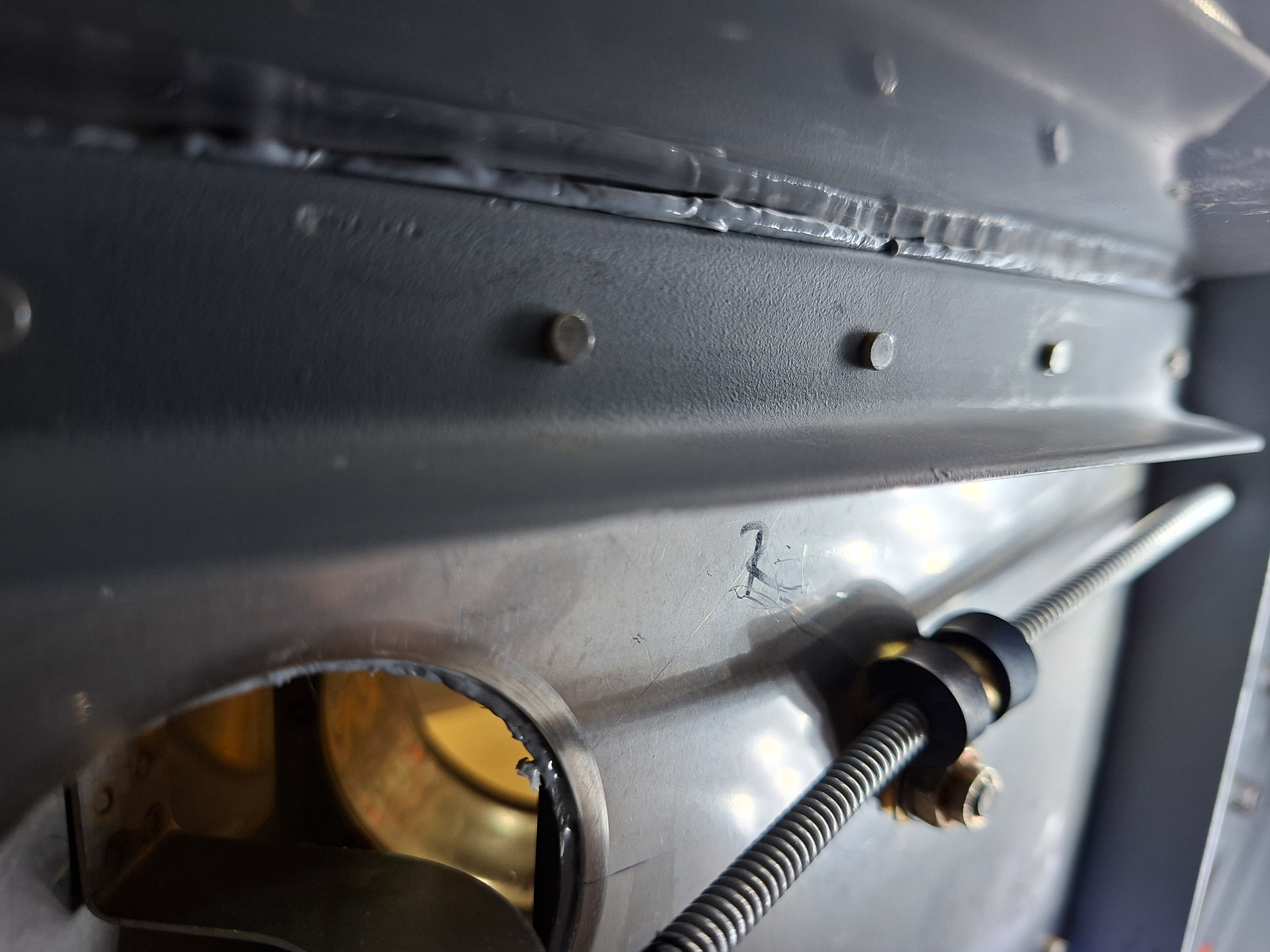
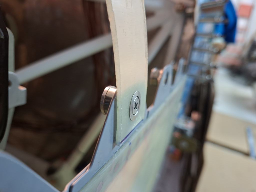
I also noticed I forgot one AN470AD4 in the bottom of the angle that attaches the upper panel rib to the firewall angle. This is also the beefy angle that supports the forward canopy support of the roll bar. It would be difficult to set it once the recess is on. I was quite happy that I could use the squeezer to set this one. I hate shooting AN470 rivets with the gun.
The squeezer did a good job on these AN470AD4-7 rivets
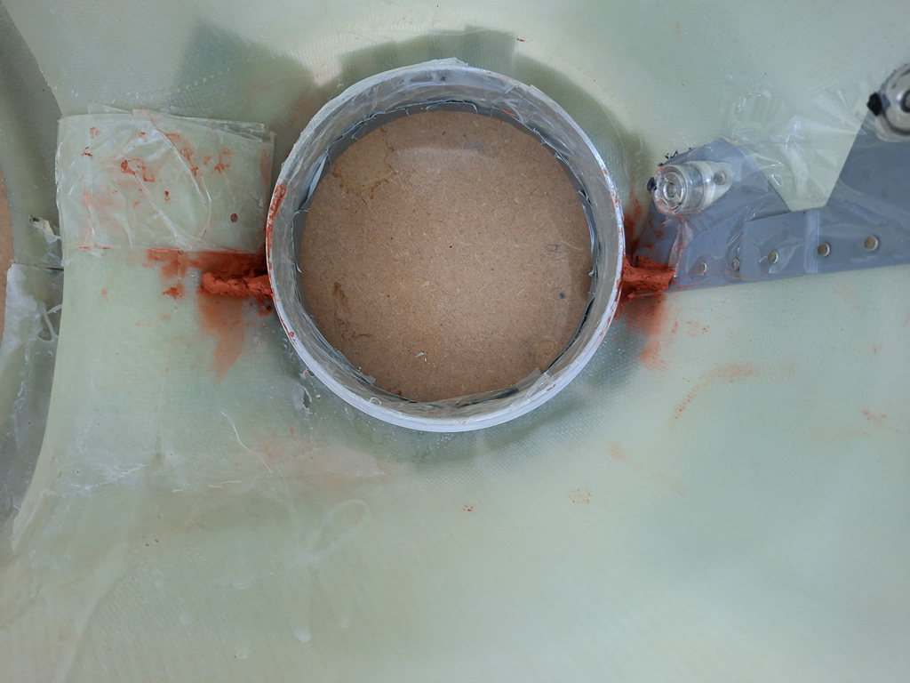
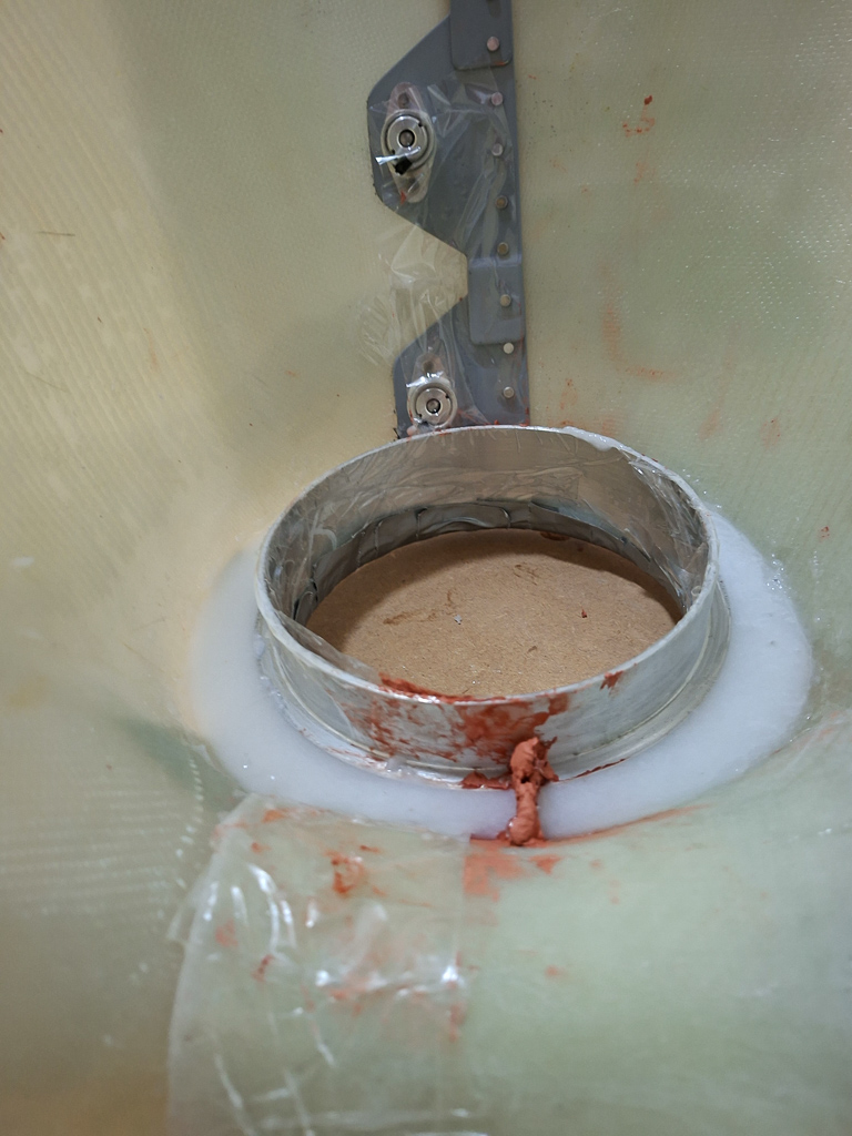
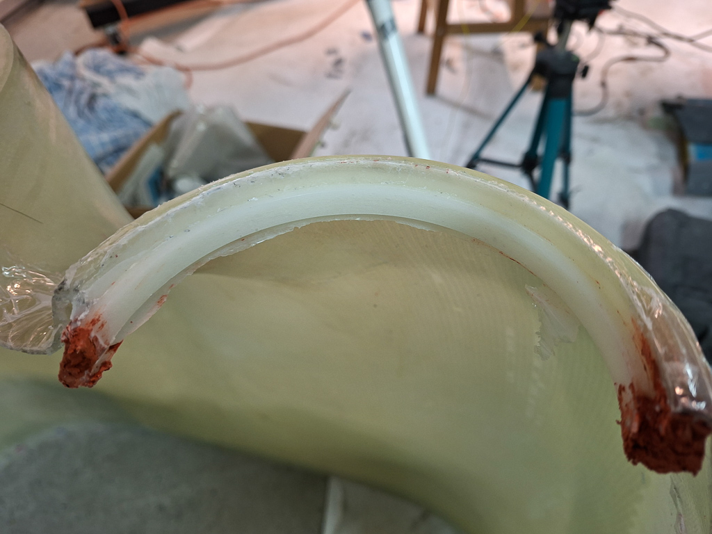
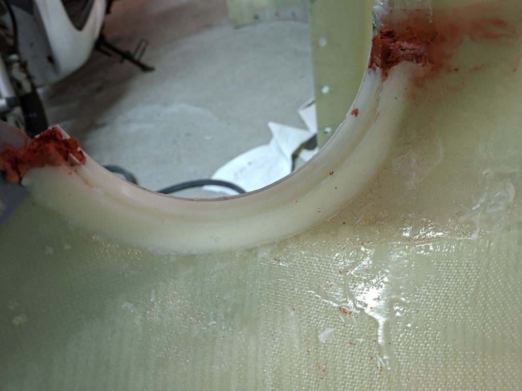
Then I got out the 3M Flame master tube, degreased the parts and evenly spread it out on the contact points
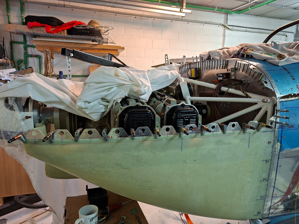
Clecoed the recess in place and applied more sealant in the joint points where a gap was remaining. You want it all sealed well to avoid getting exhaust gas fumes (carbon monoxide (read as: "death")) out of the cockpit in case of a exhaust break or leak.
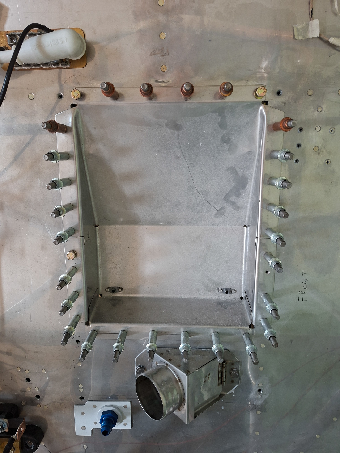
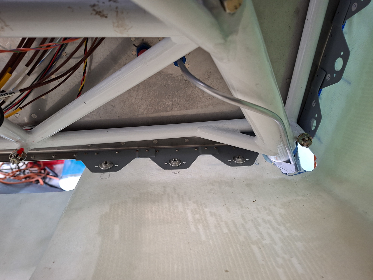
This is how the recess looks from the inside
This will have to cure now and next I will be rivetting the recess on.
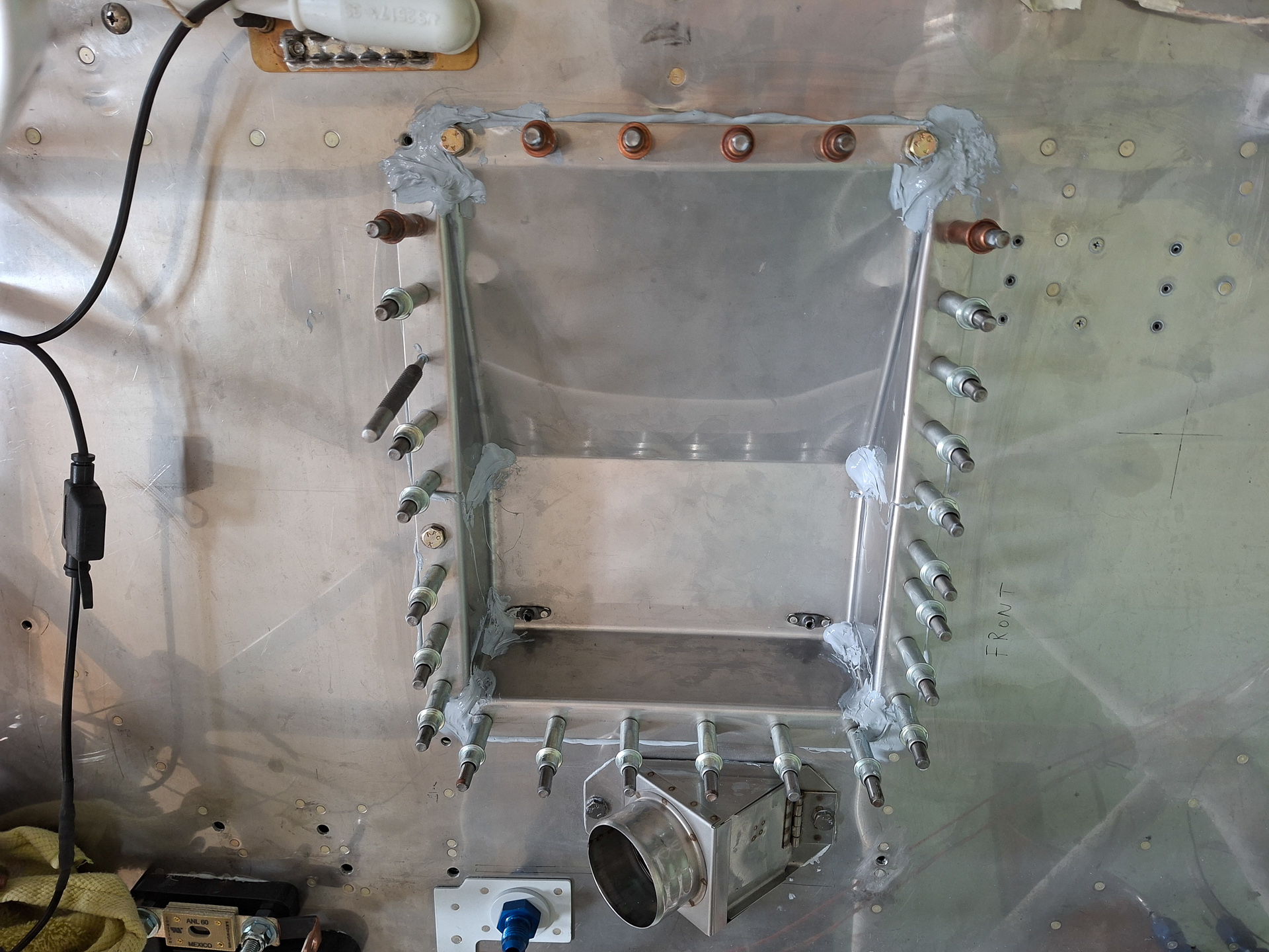
15+16/07/25 - rivet firewall recess - 2h30
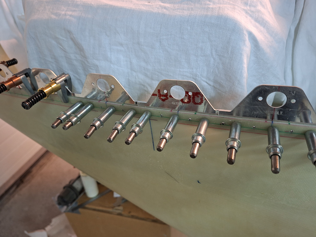
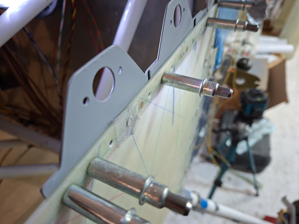
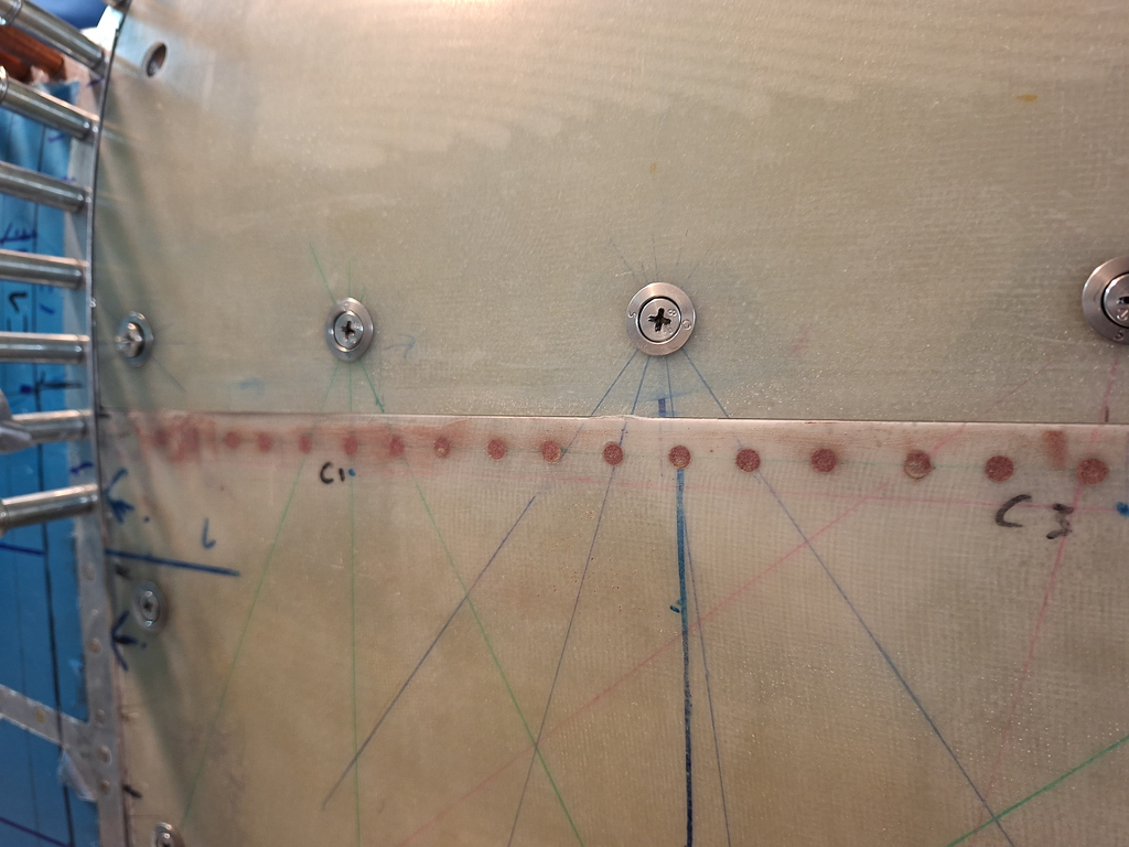
Some short sessions with Matthias to rivet the firewall recess to the firewall stiffener angles. The sides and bottom are all AD3 rivets, the top row is AD4.
The space is limitted with all the stuff that's in the way like electrical conduit, parking brake cable,... I detached the conduit to make room for the bucking bar. When you install the recess, don't forget to set the rivets on the rudder brace first as this can only be done before the recess is in. (the AD4 rivets on the white plate)
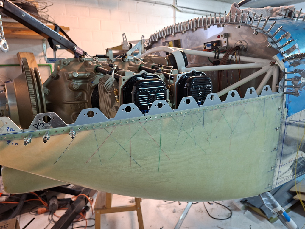
Both sides rivetted. Had to redo some but after all an easy task.
The sealant goo is leaving a mess on the inside as well, will have to do some cleaning up when finished.
the side rivets could be bucked from the outside of the plane leaning over the sides of the firewall.
Then we continued on the bottom row. This can only be done from within the fuselage with your head between the rudder pedals. Not very comfortable and since I'm wearing multifocal glasses, things haven't become much easier down there.
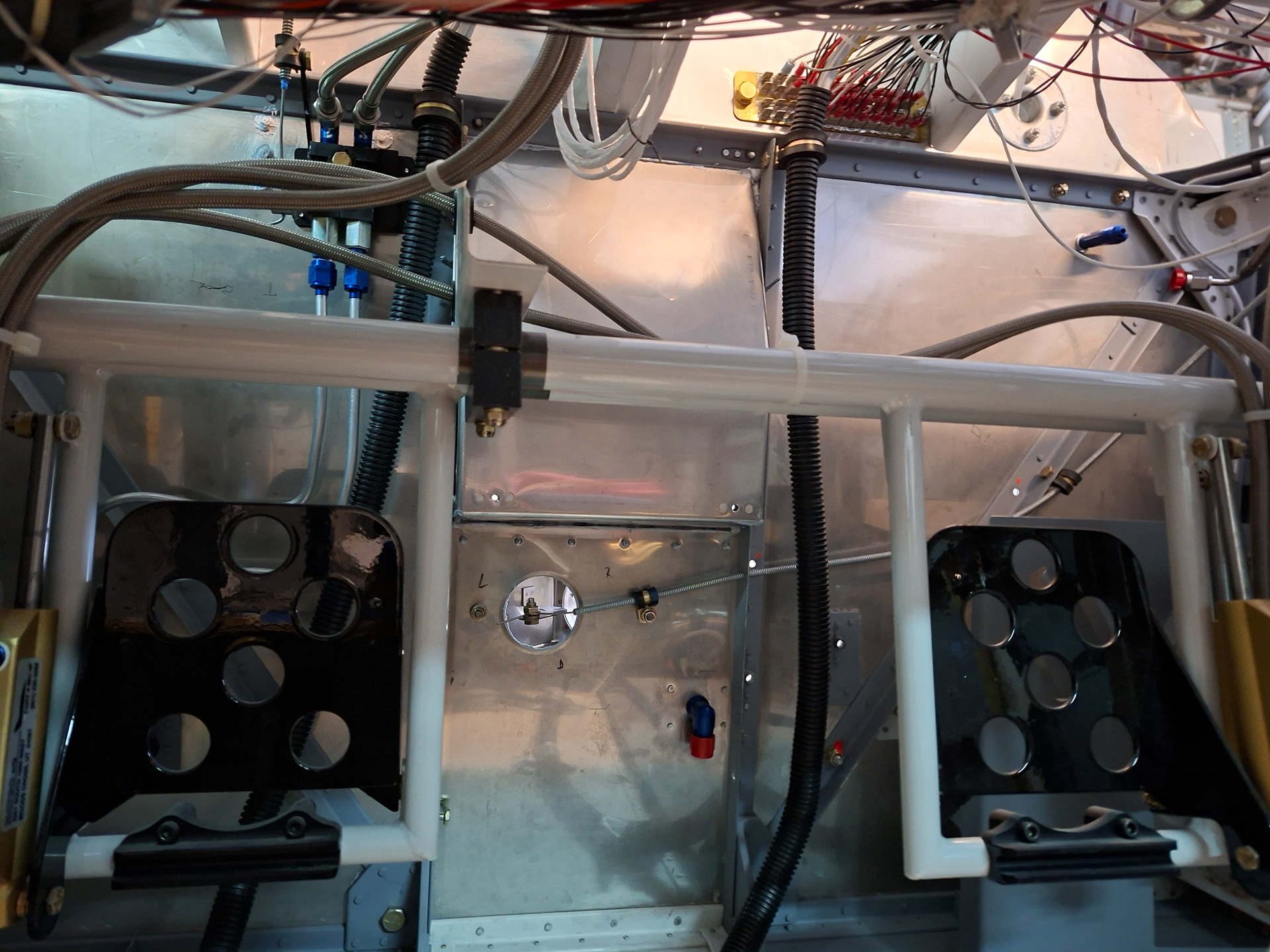
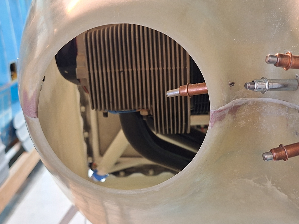
16/07/25 - Dynon MAP sensor on Firewall - 2h
I have a fixed pitch Catto prop and no constant speed, so you might ask why I'm installing the MAP pressure sensor anyway.
MAP allows for more accurate power measurement of your engine. Unlike RPM alone, MAP gives a better indication of the engine load. At the same RMP setting MAP pressure might vary significantly. MAP fills the missing piece of info to estimate the true engine power output more accurately. RPM can be significantly misleading cruising at altitude due to the thinner air. Having EGT and fuel flow, MAP allows to lean more precisely and help under of over leaning especially at altitude.
MAP naturally decreases with altitude and is giving a simple and intuitive way to understand density altitude effects on engine performance.
Abnormal MAP readings at given known throttle positions can point to intake leaks , valve issues or air filter obstruction.
In general it's just another parameter to evaluate your engine's health.
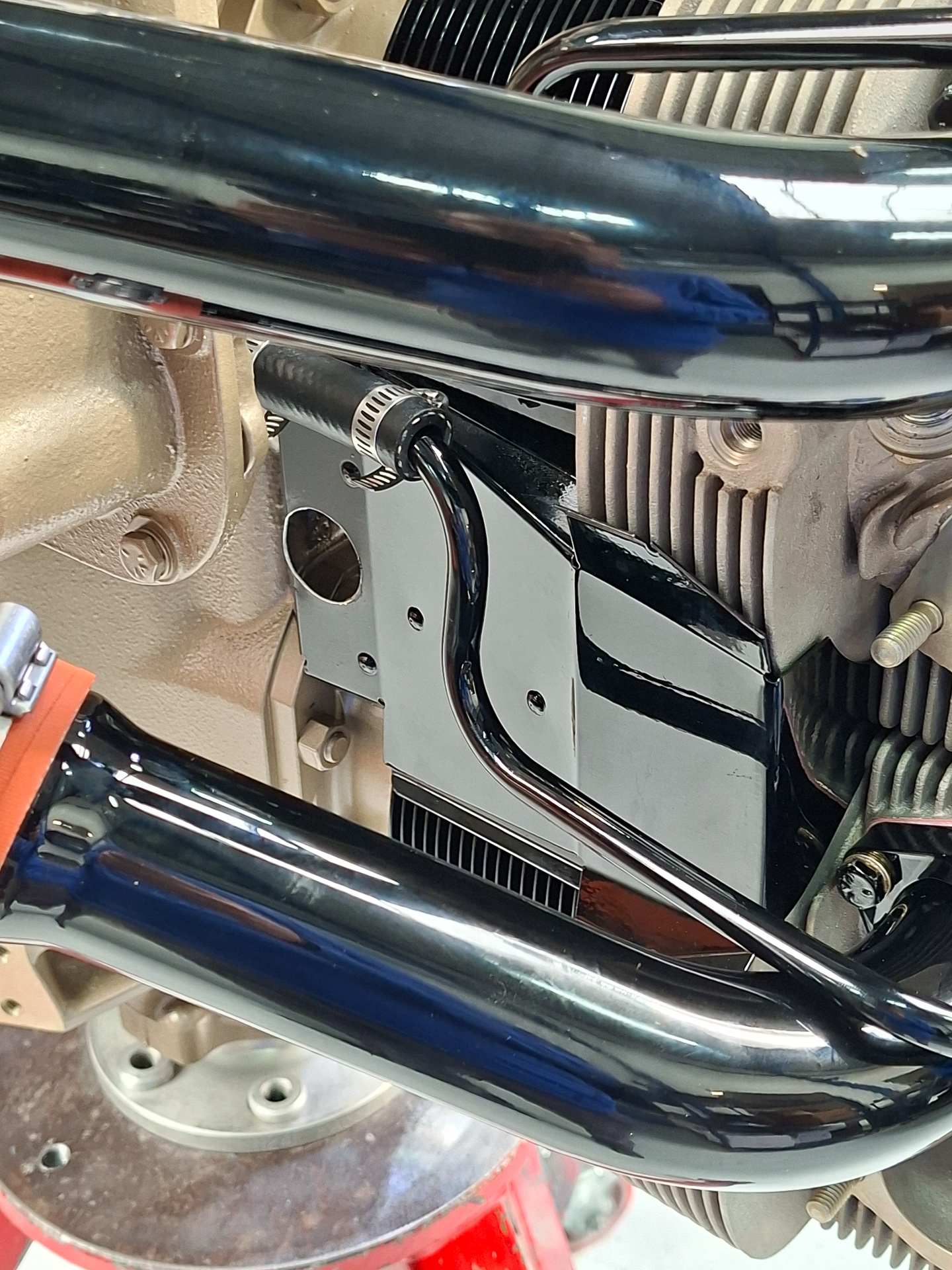
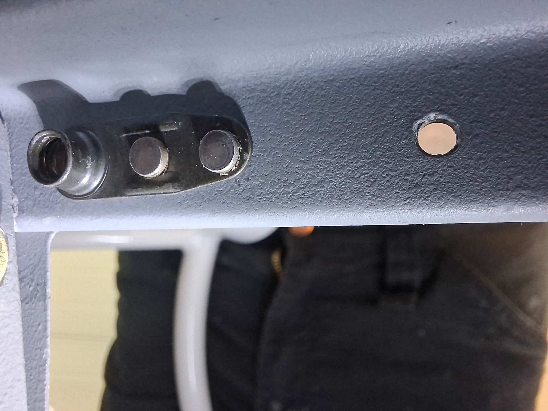
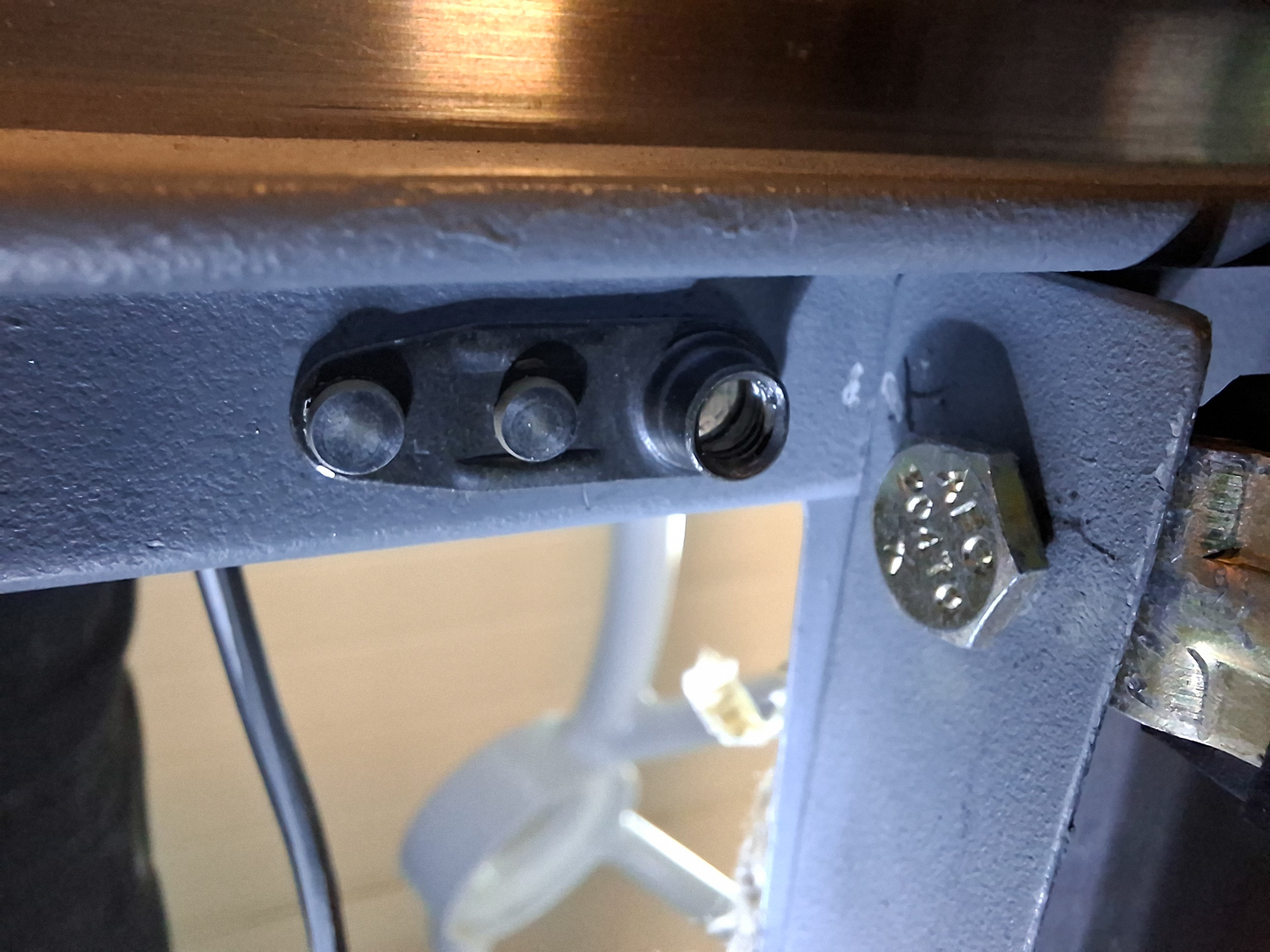
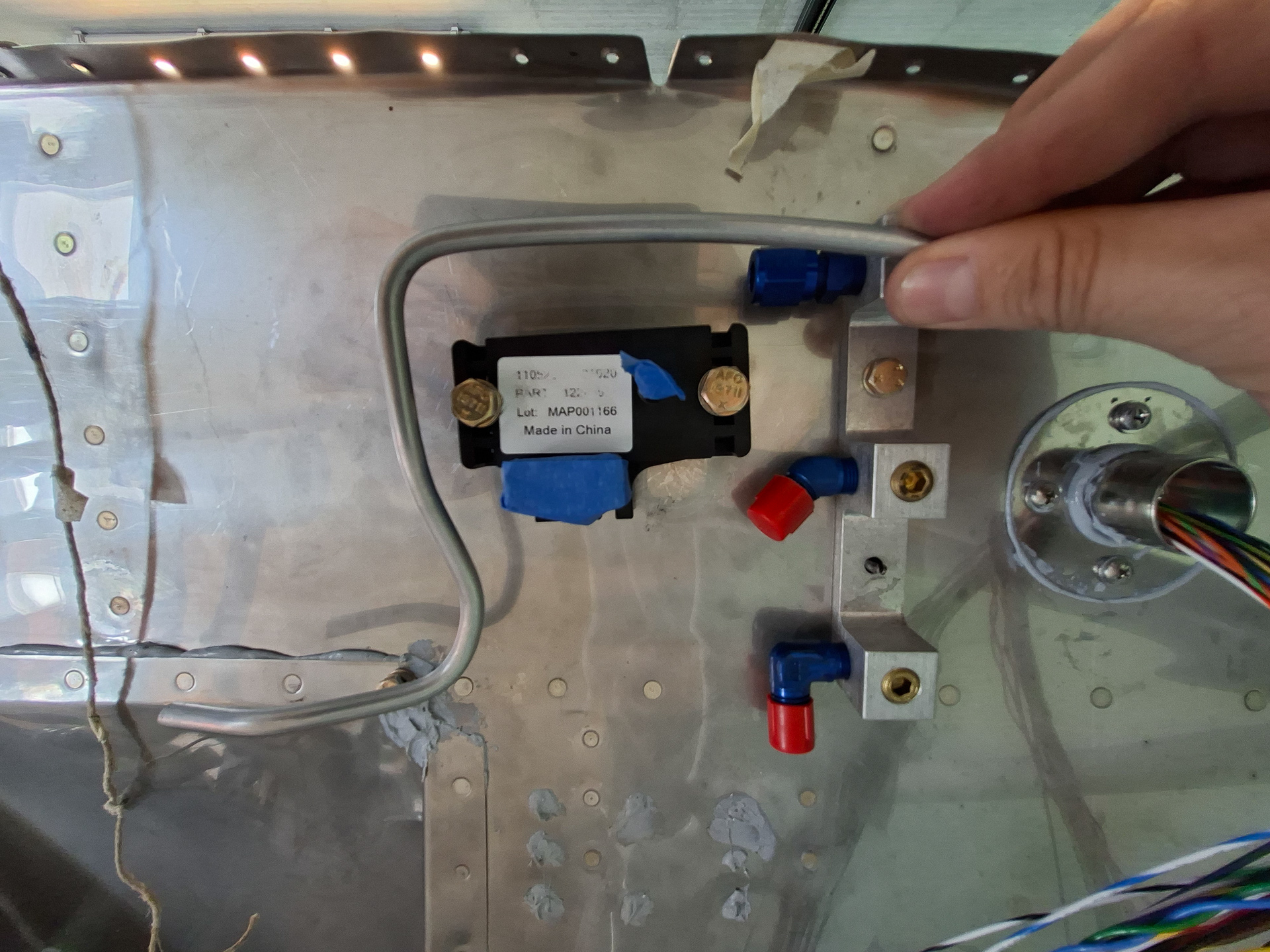
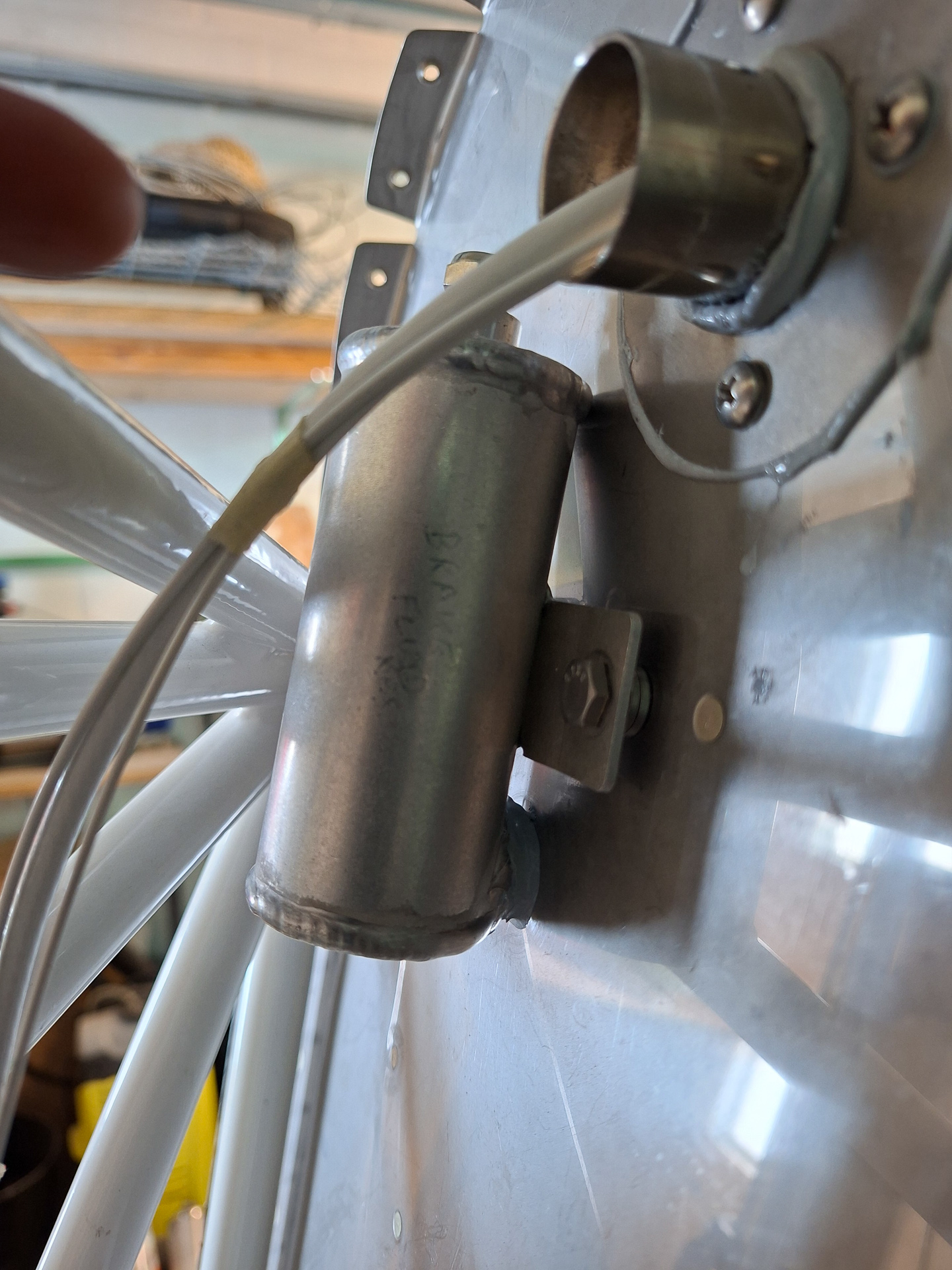
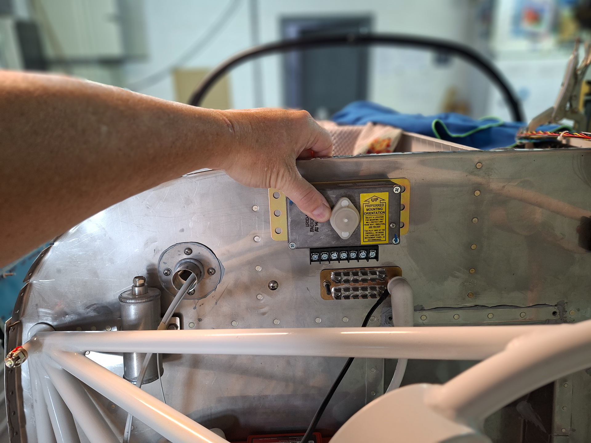
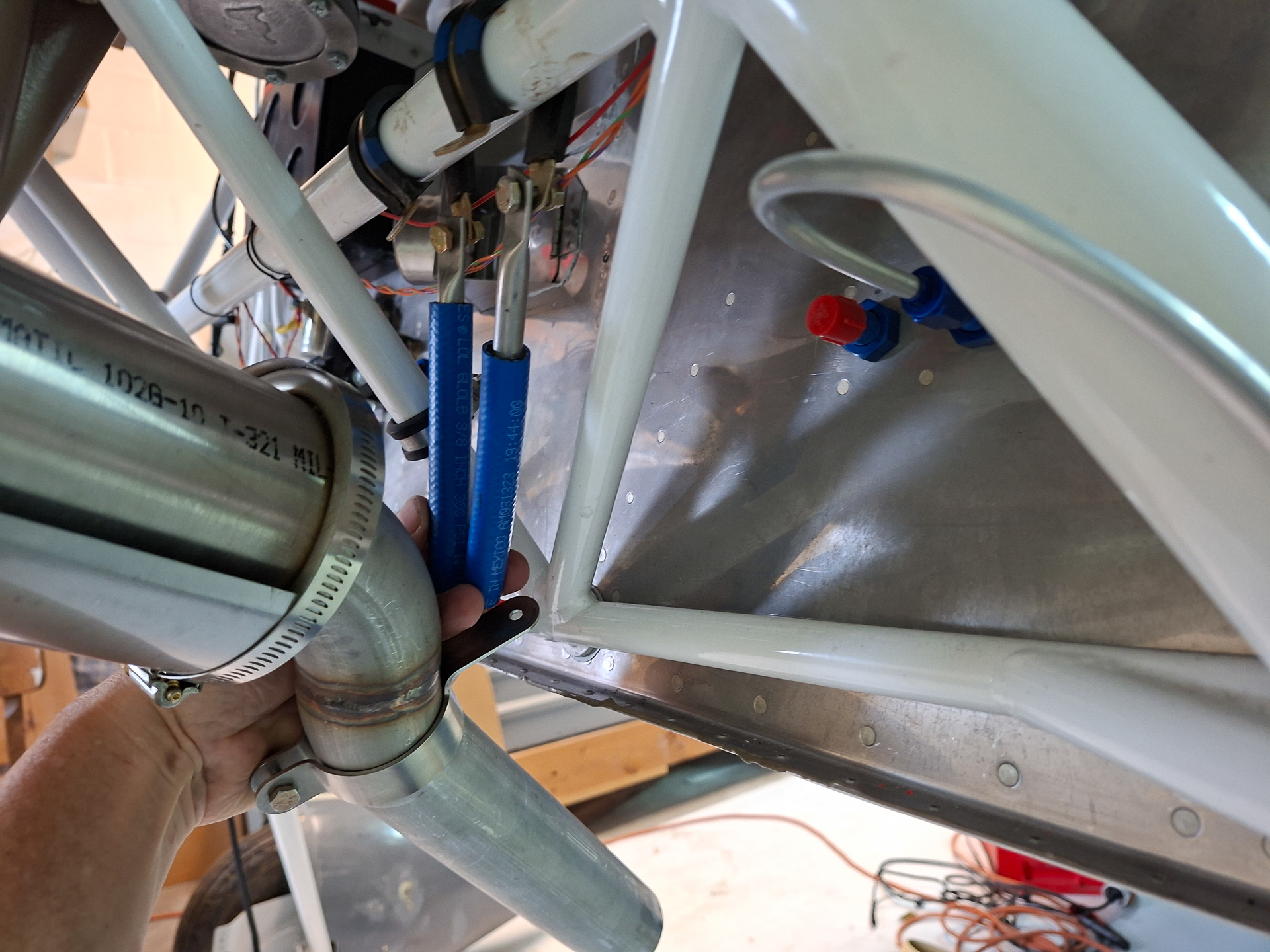
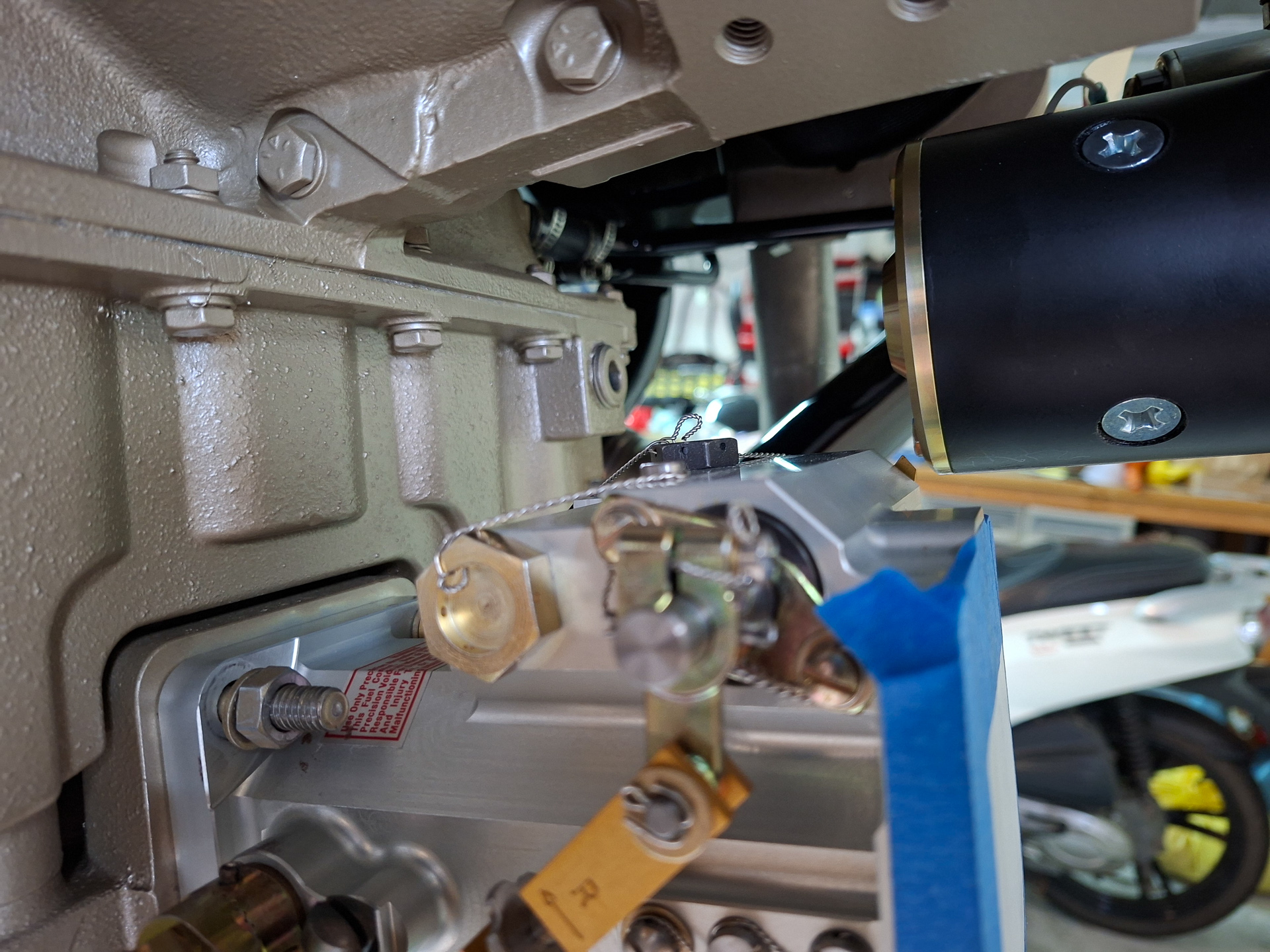
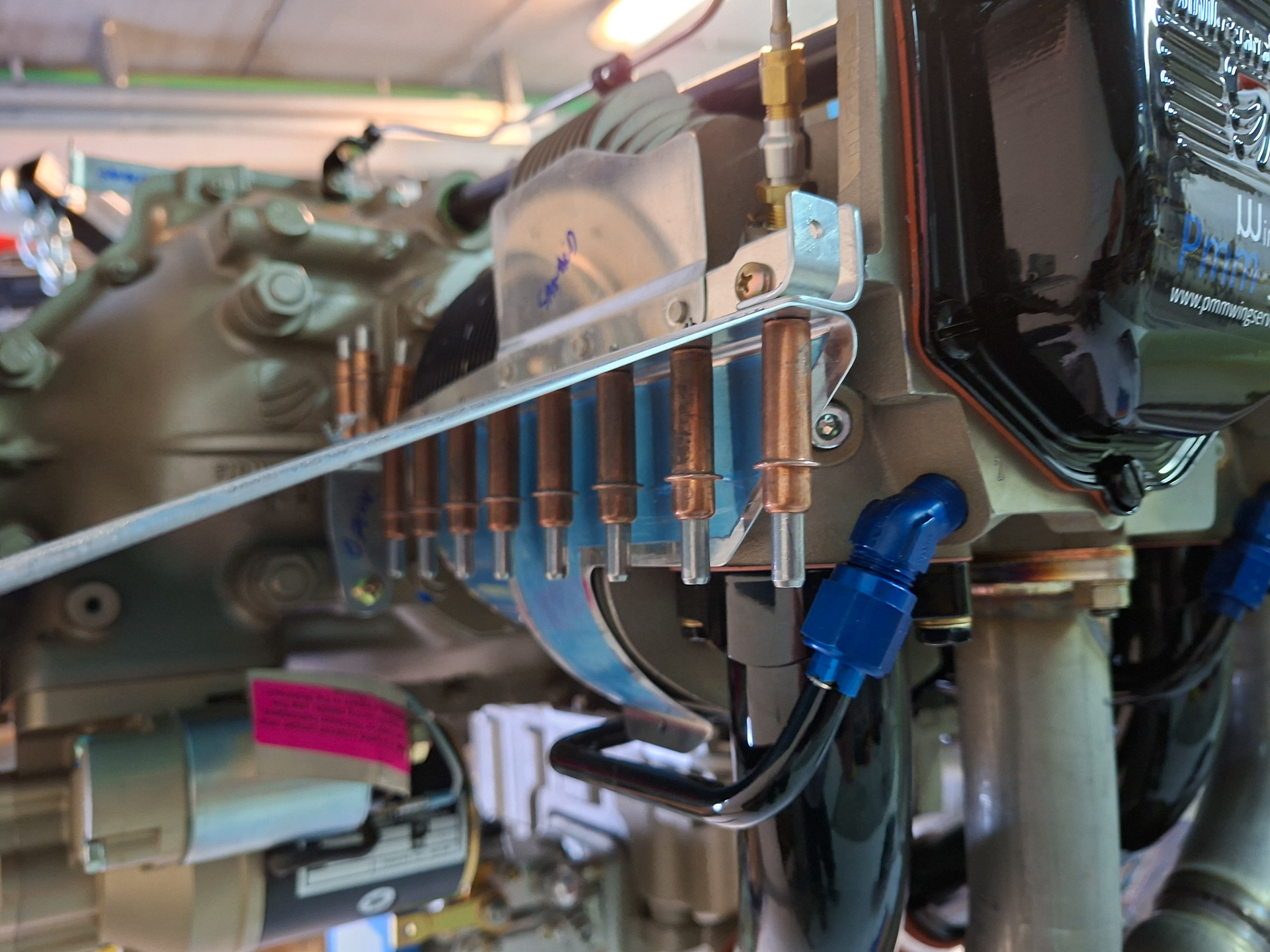
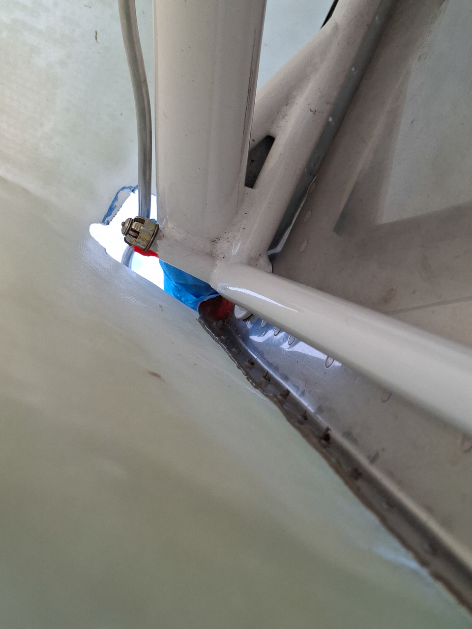
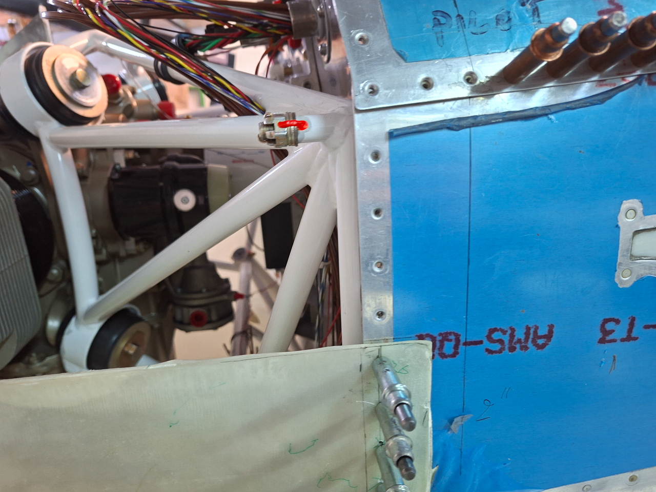
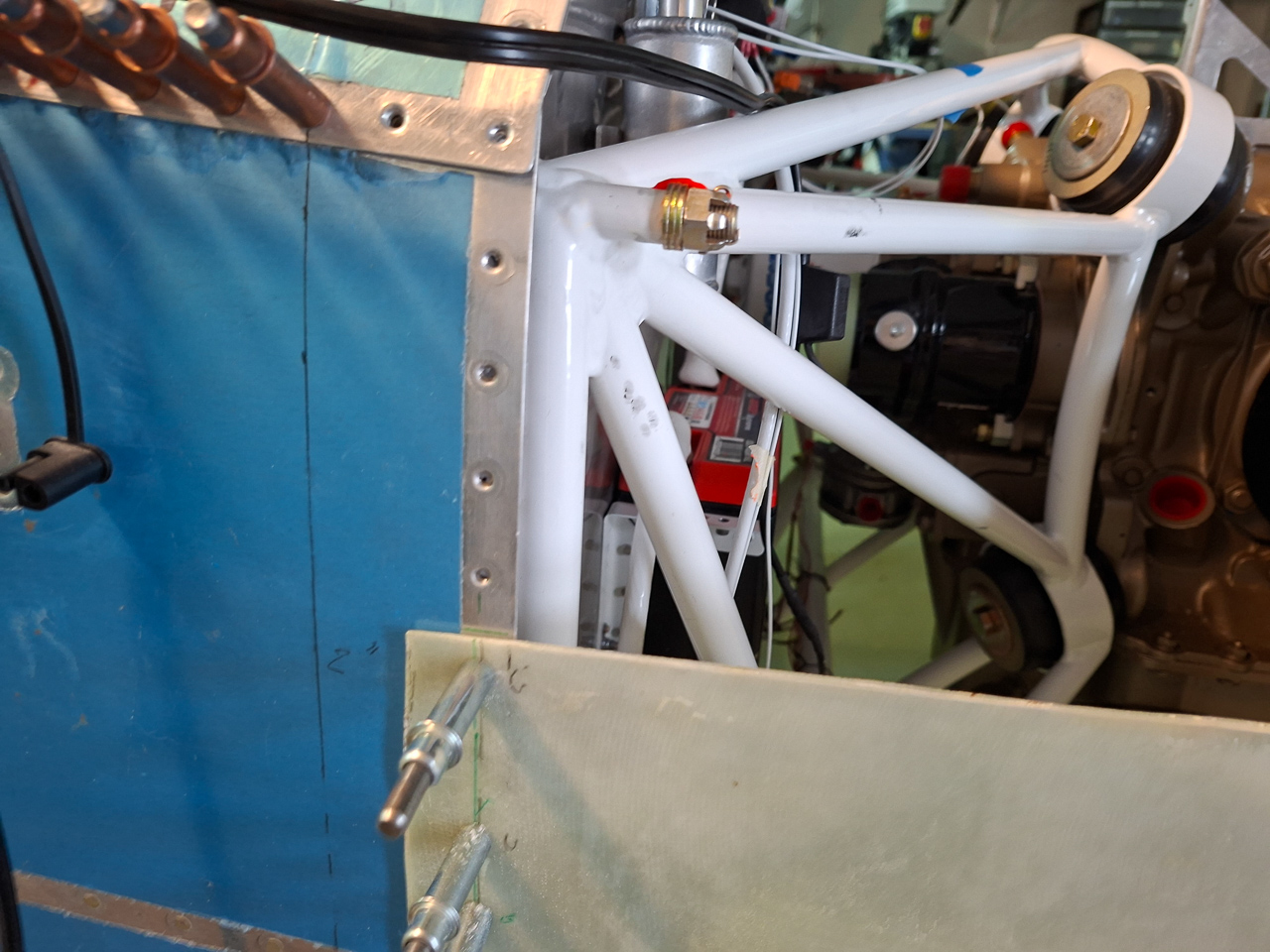
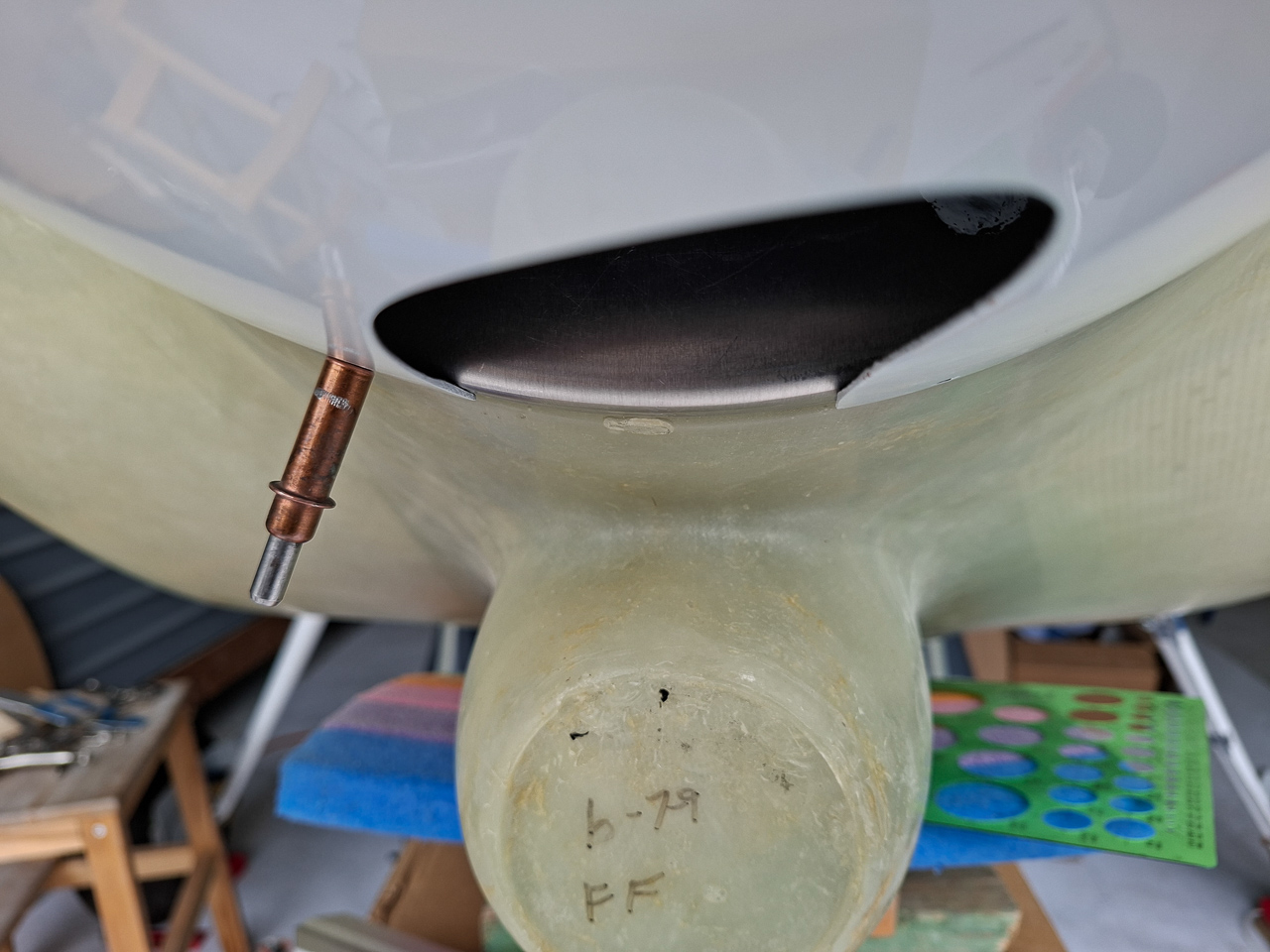
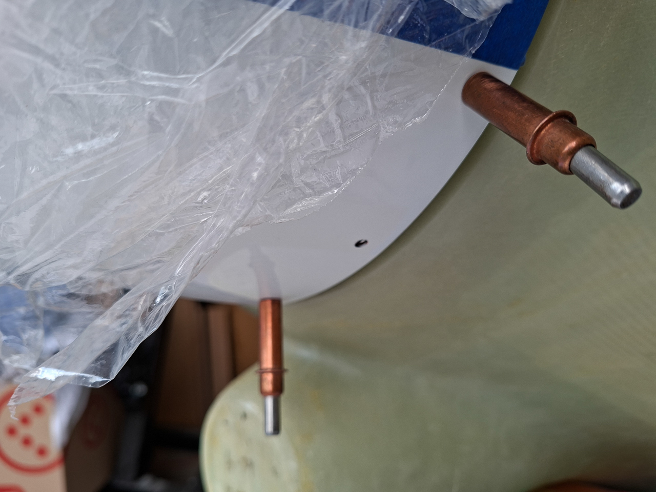
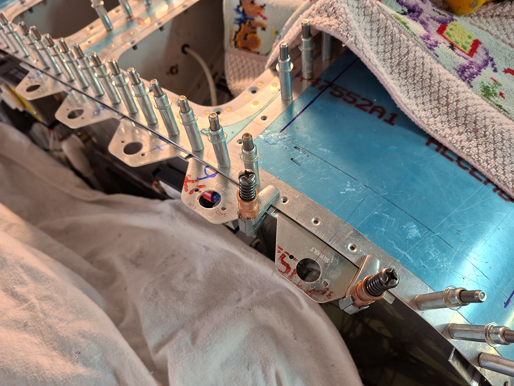
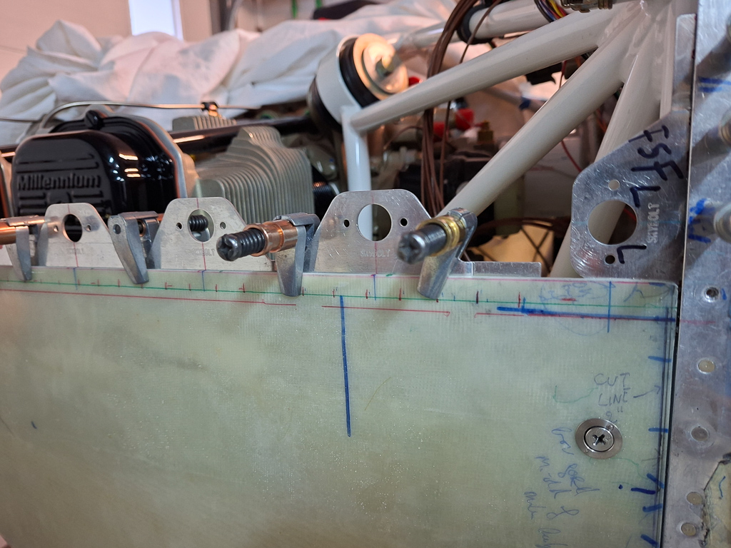
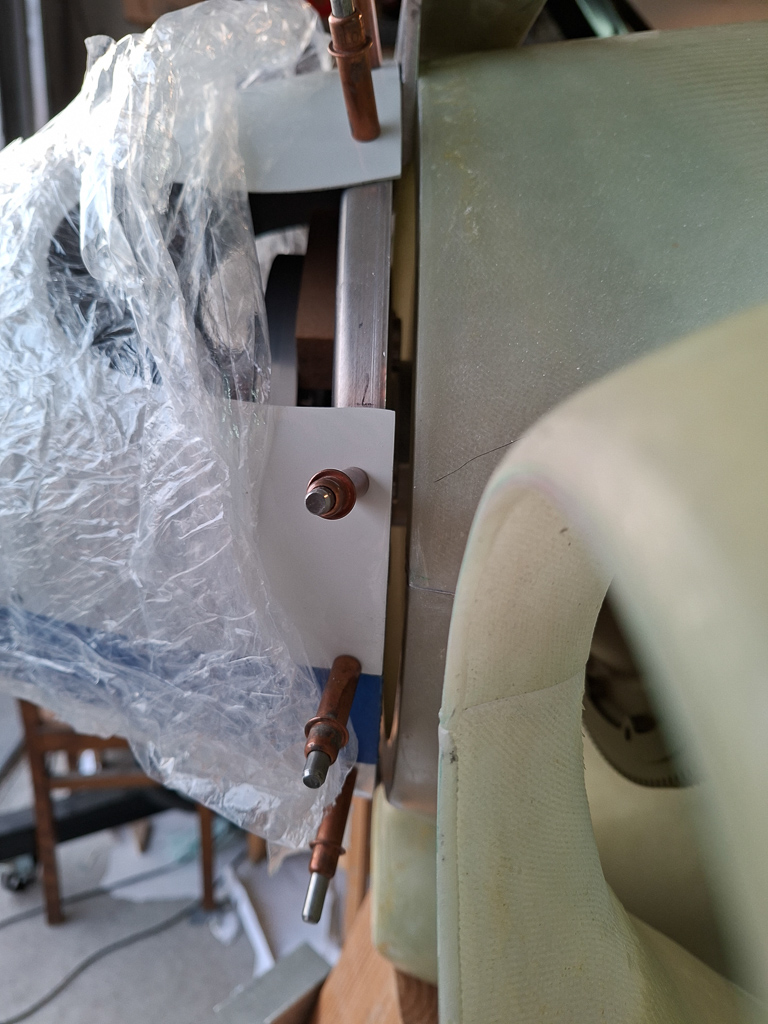
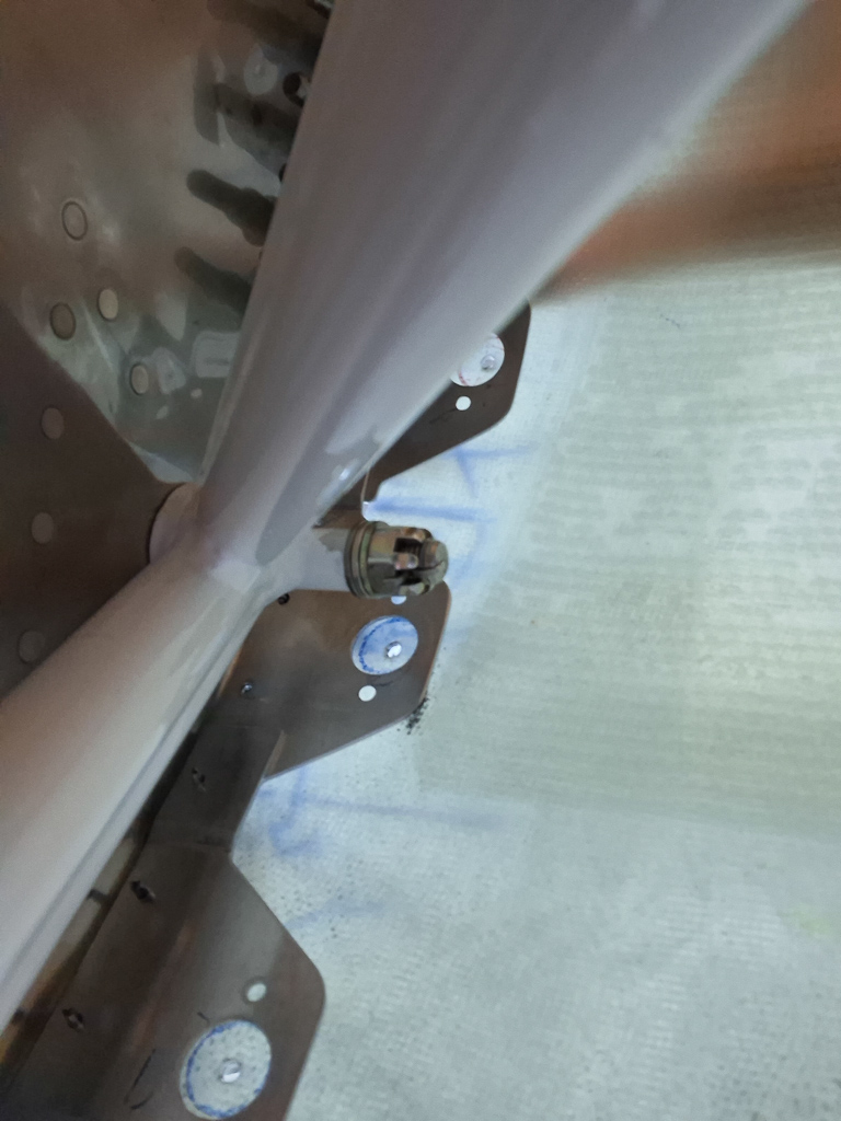
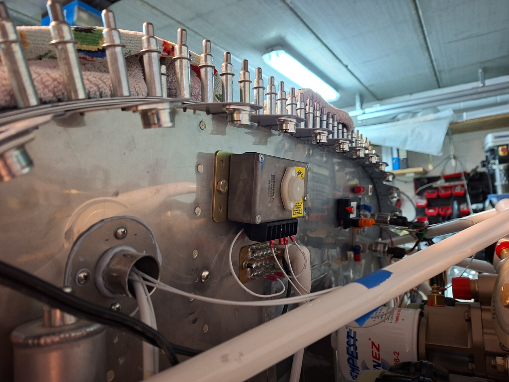
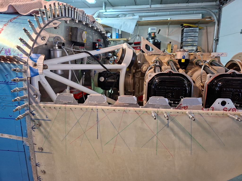
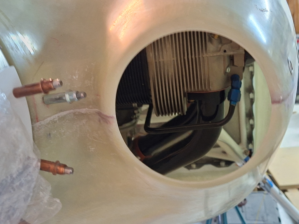
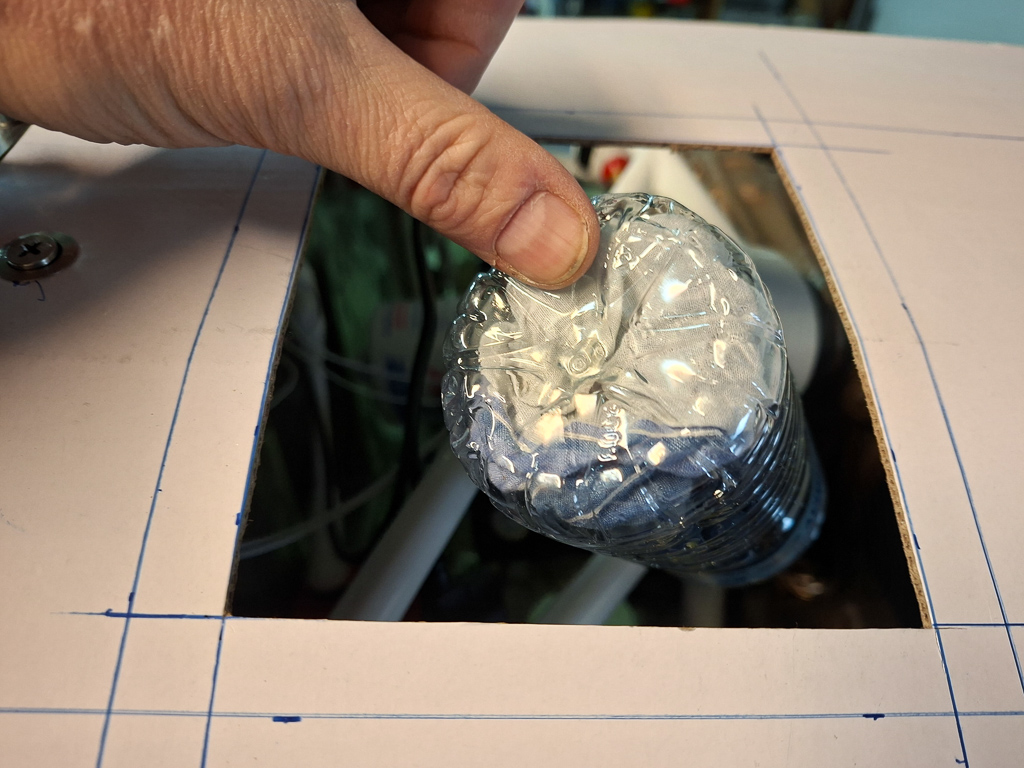
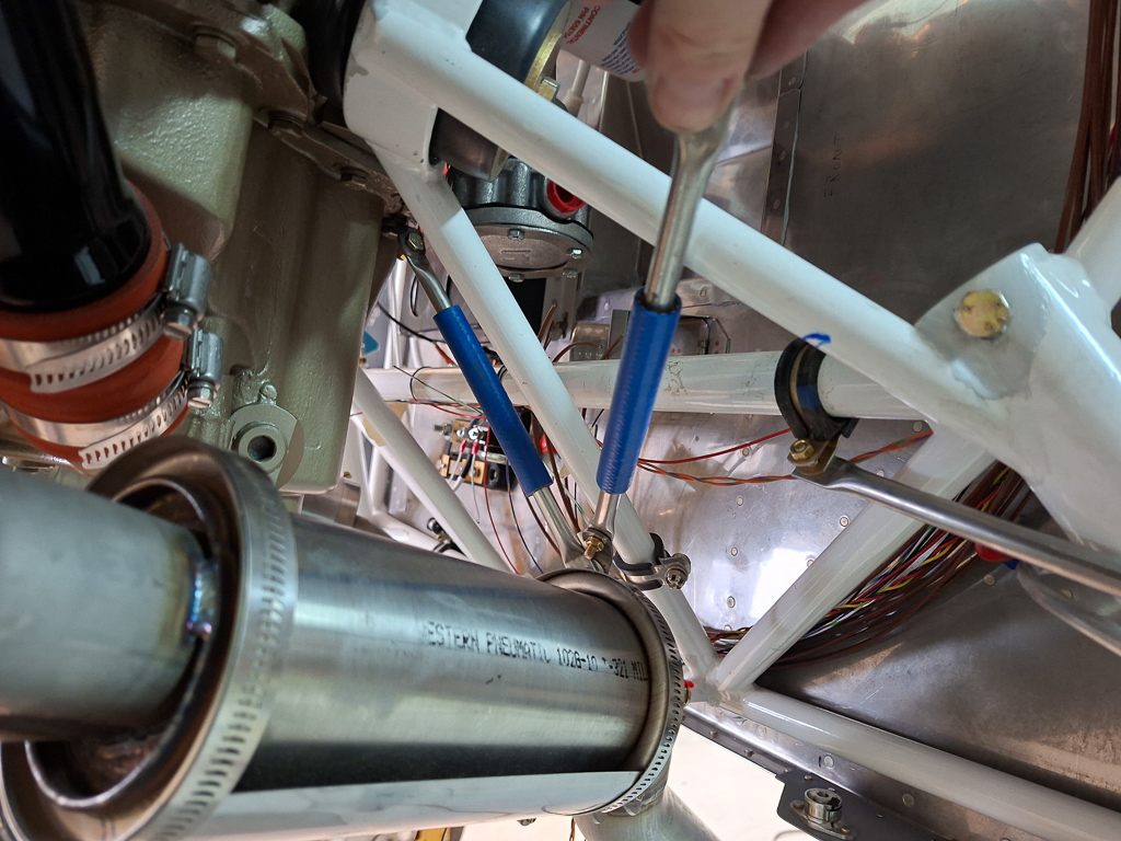
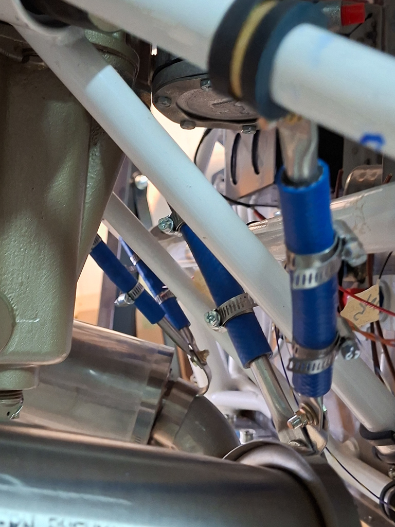
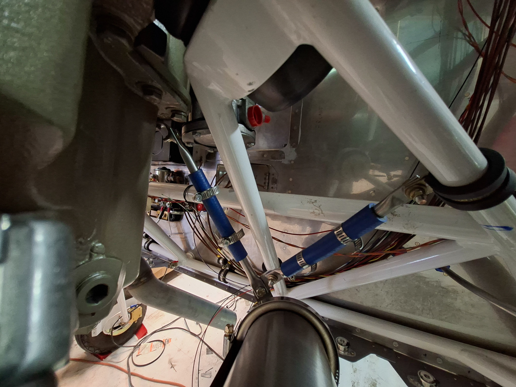
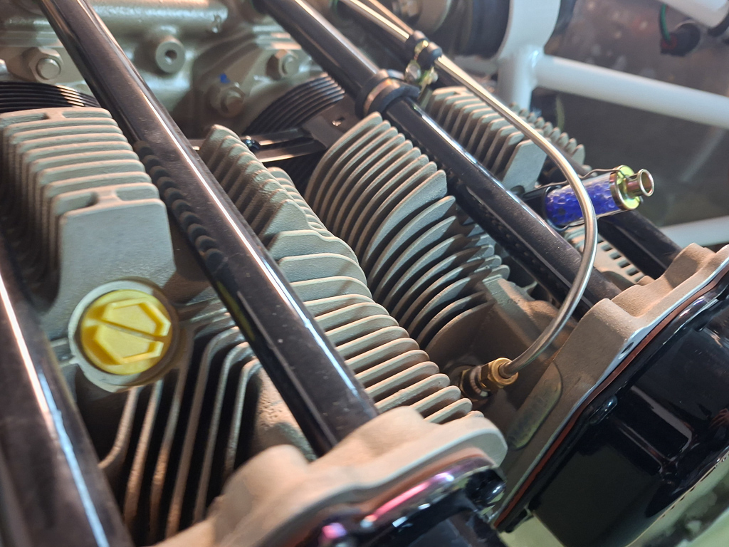
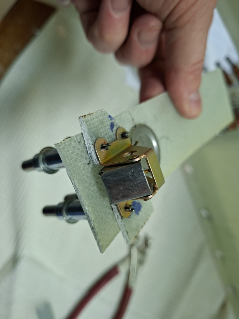
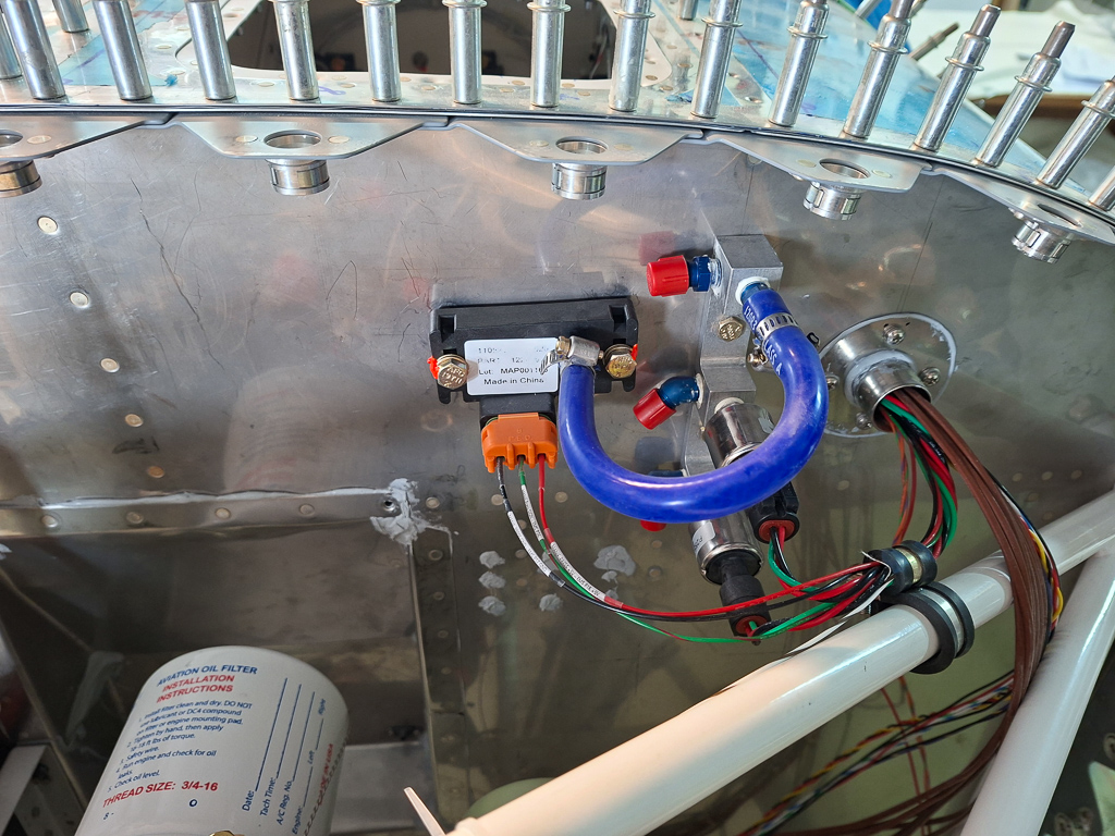
The Dynon MAP sensor comes as part of the EMS wiring kit and is the black plastic box that takes two electrictal wires through a weather safe connector and a tygon tube input of 1/4" to receive the air pressure input. The air is tapped from the cylinder 3 port on the engine. I plan on running a flexible breaded hose from cylinder 4 out of a AN816-4 fitting in the engine. The flexible hose will bring it to the firewall. From the firewall there will be an AN837-4D (Elbow Flared Tube Bulkhead And Universal 450) with AN924 nut with an angle on the firewall to make the transition from the flexible to a fixed aluminum tube line that will lead straight into the transducer manifold top port. In the transducer port forward opening, I will install an AN840-4D hose fitting to allow the transition to a tygon plastic tube to run into the MAP sensor front port. If later on, I decide to go with PMags or need MAP for any other gauge or application, I can easily tap of here.
So the best mounting place for me seemed to be close to the transducer block, making sure there's still space for the oil pressure line fitting but keeping the tygon pressure tube as short as possible.
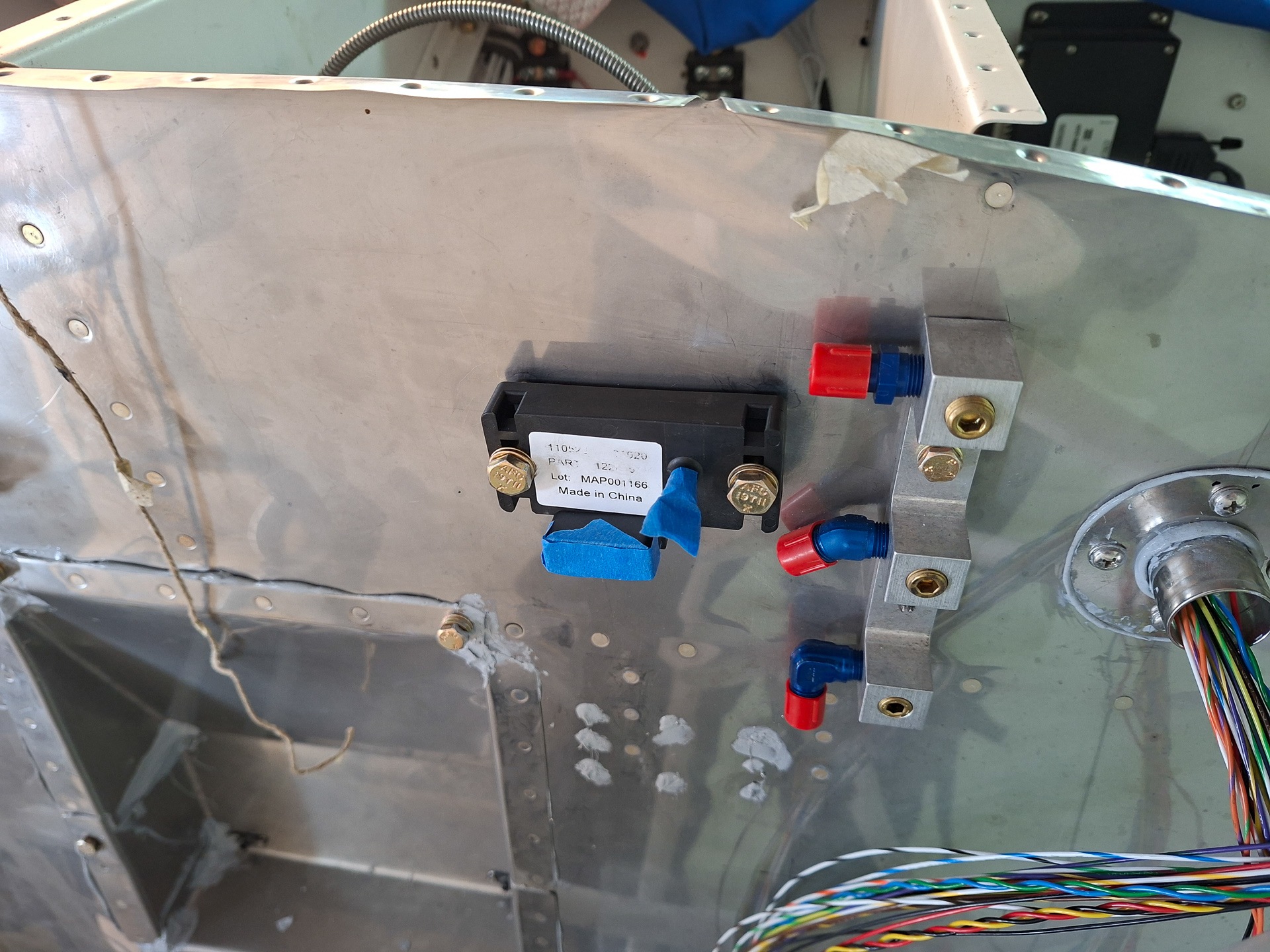
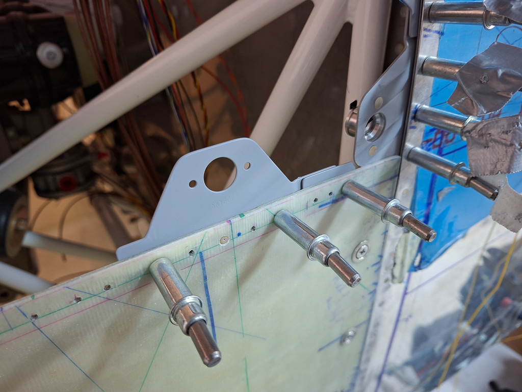
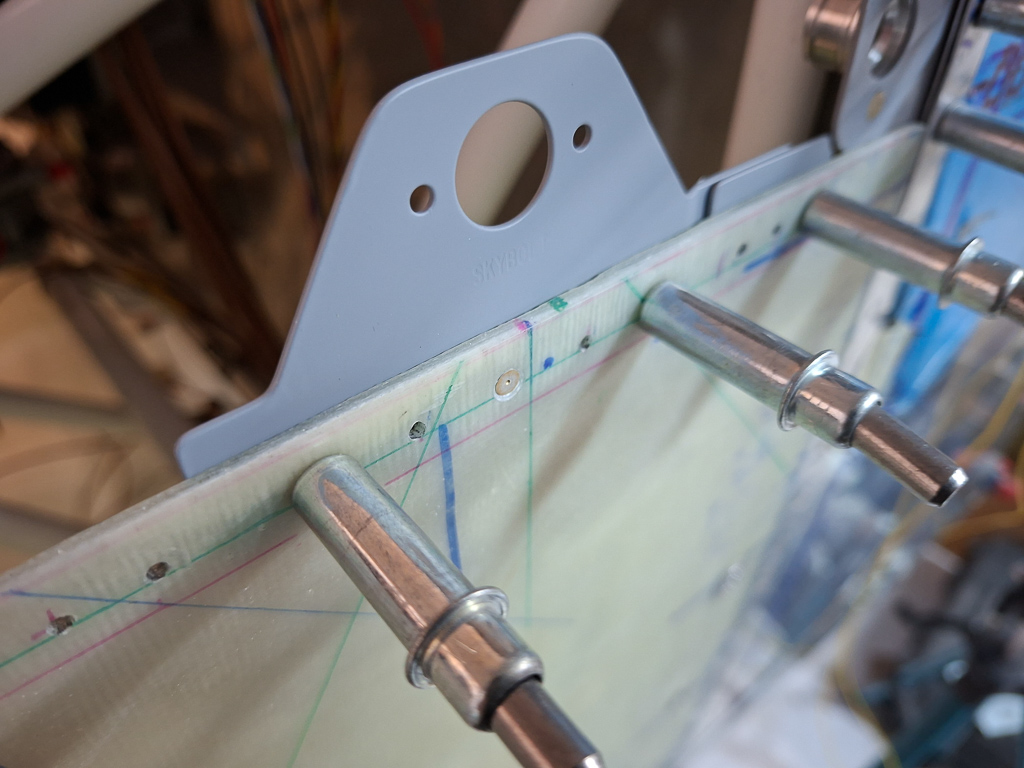
Drilled the holes for 2 AN4 bolts to hold the MAP sensor. This is way overkill as it's just a plastic box with no weight but the holes were predrilled in the plastic.
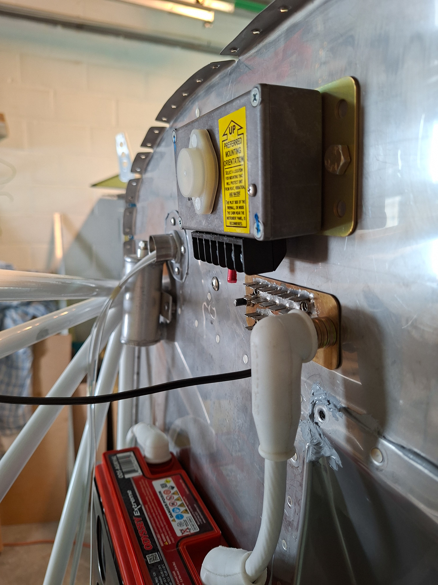
Installed the nutplates and torqued down the AN4 bolt in the K1000-4 nutplates. I fastened them by hand as the case is plastic and you shouldn't over thighten it.
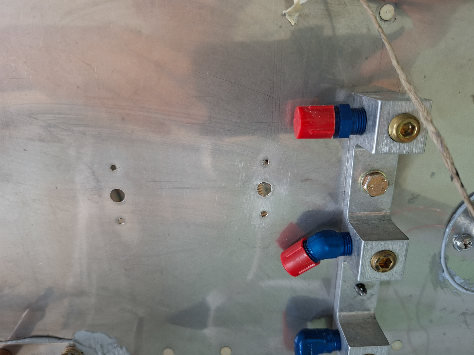
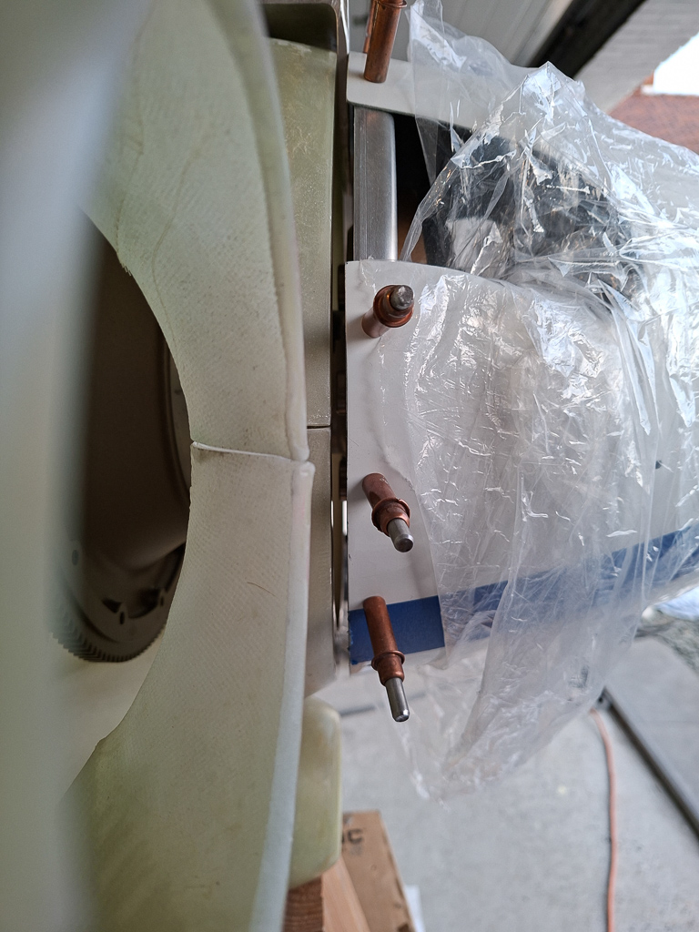
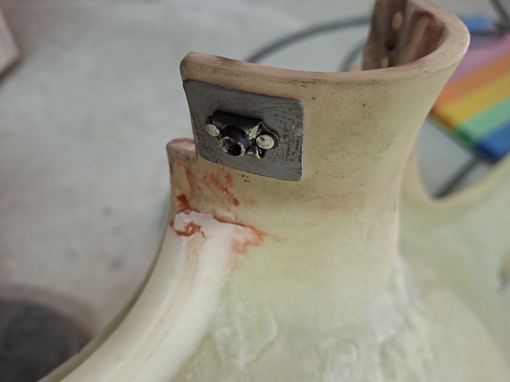
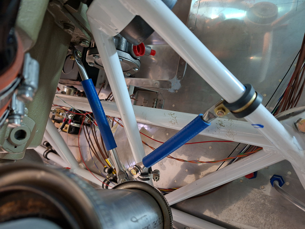
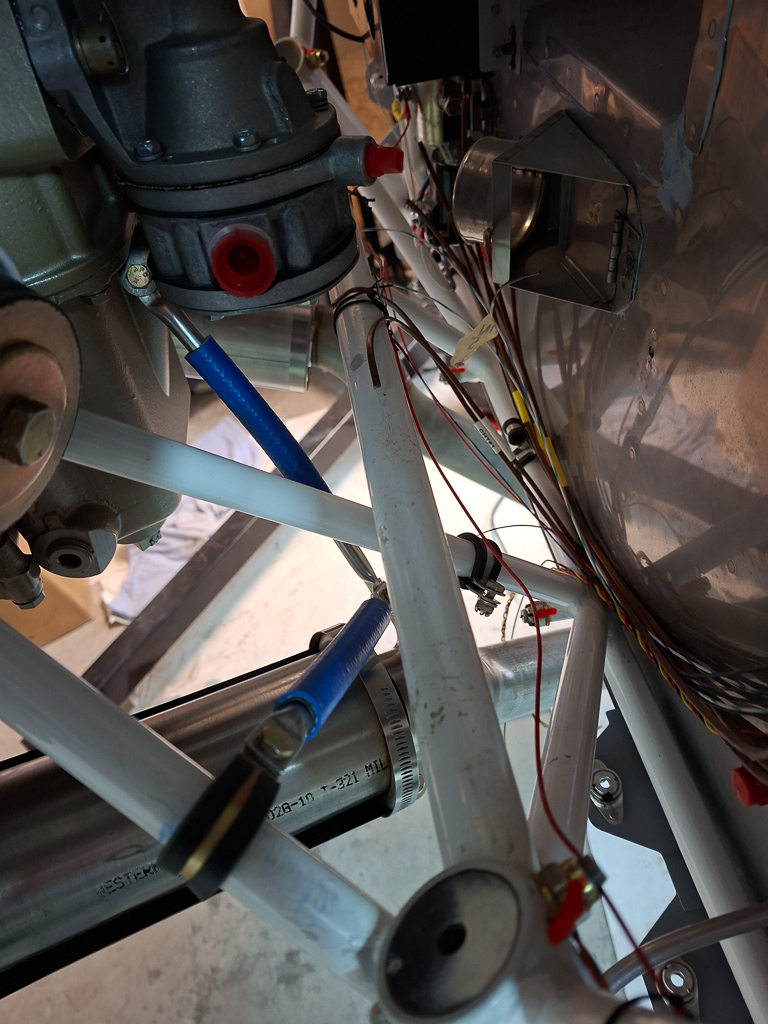
Look from the front in the attached location with the AN fittings installed in the transducer block.
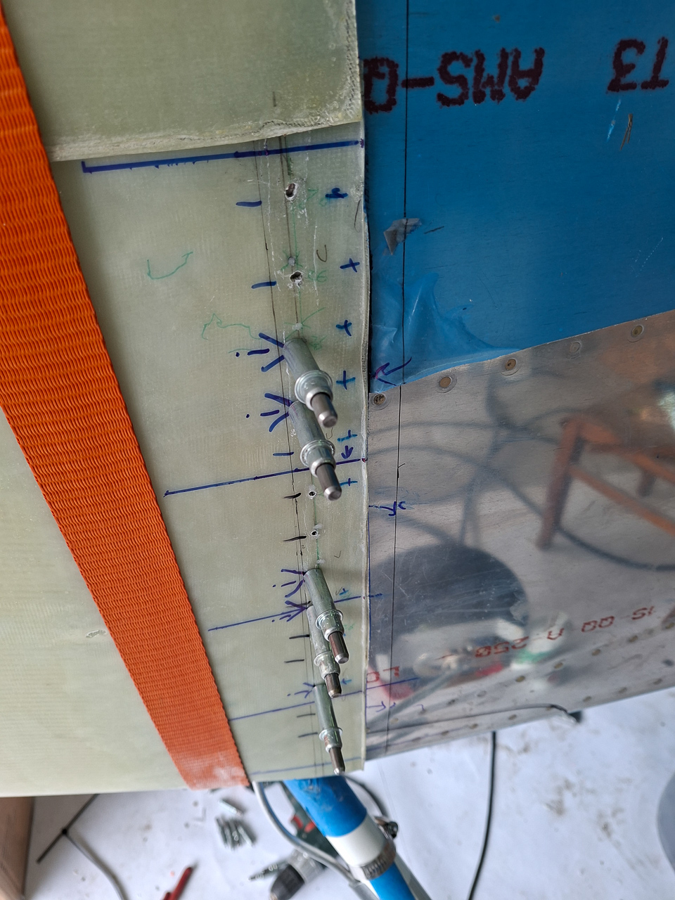
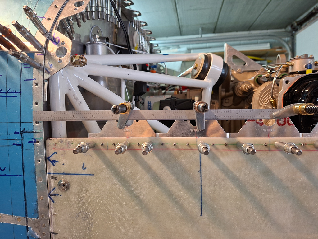
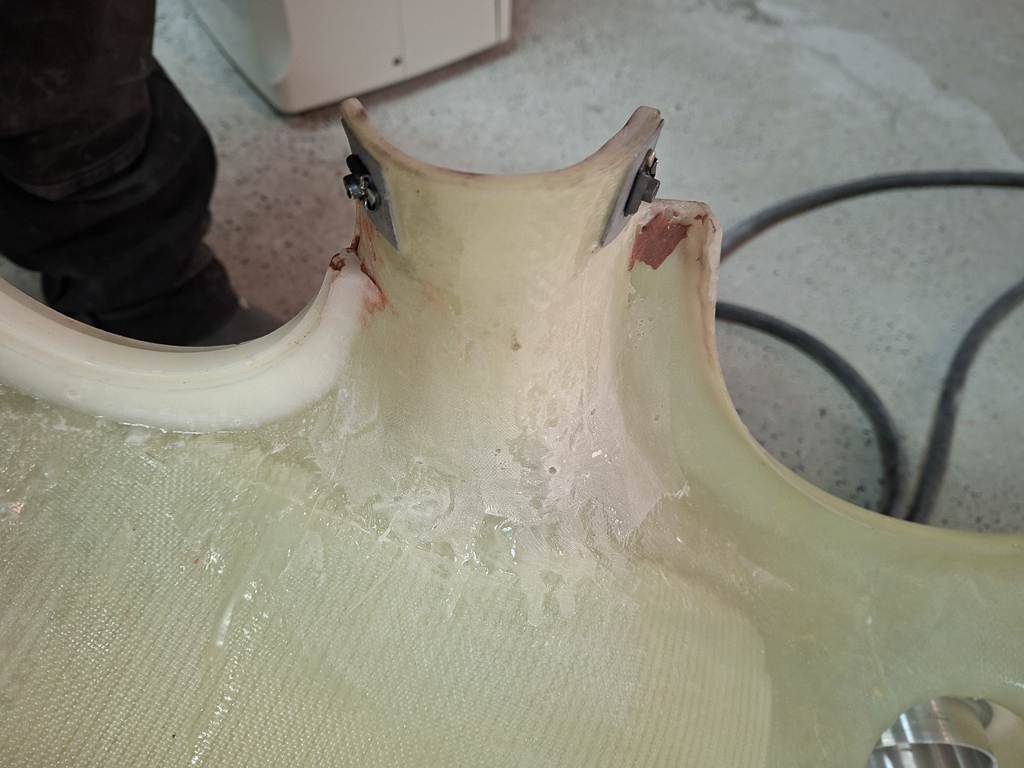
I had some bend aluminum tube in my scrap so i gave it a little test to see how this would run to the other side along the firewall. There will be 2 additional adel clamps where the oil pressure line is attached (top of the recess) which will hold this aluminum tubing.
19/07/25 - Firewall preparation / retorque gear leg and engine mount - 6h30
A lot of small tasks done in further preparation of the firewall to receive the engine.
As I was installing the fuel pass through doubler and rivetted the firewall recess, I had to remove the battery box and contactors. So first I reinstalled all those components.
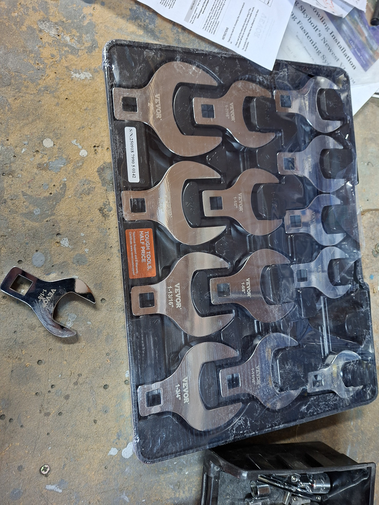
I recently have purchased 2 new top-of-the-bill digital torque wrenches from SNAP-ON. I had found that my old one (purchased at the beginning of the project was undertorquing) and I bought a new one from WERA but the snap through mechanism on that one just didn't give me the required confidence of precision. So when I went to PMM wingservice for assembling my engine, I saw Patrick using these SNAP-ON wrenches and was convinced that was the right tool to purchase.
So I bought the Snap-On TECH2FR100 and TECH1FR240. Expensive stuff... but so is the hardware are attaching so it's worth every penny.
Having those in the shop now, I retorqued the Engine mount castle nuts and the landing gear nuts.
The engine mount nuts are for AN6 bolts which require 160 - 190 inch/lbs torque. The technique for torqueing castle nuts is to torque to the minimum, so 160 in this case and then see where the opening lines up for the cotter pin. Don't just add torque until the alignment without checking the final applied torque. With the digital torque wrench, you can see how much you actually pulled and I was blown away how fast the torque grows on small amount of extra rotation. The one in the picture below was an example of that. After adding the required torque from minimum, I ended up with 220inch/lbs. In this case, remove the nut again and either use a different nut which might have different alignment or add an extra thin washer. This will change the position of the minimum torque and in the end allow you to get within the acceptable torque range.
All of the 6 engine mount bolts were close to 180 in/lbs on final install.
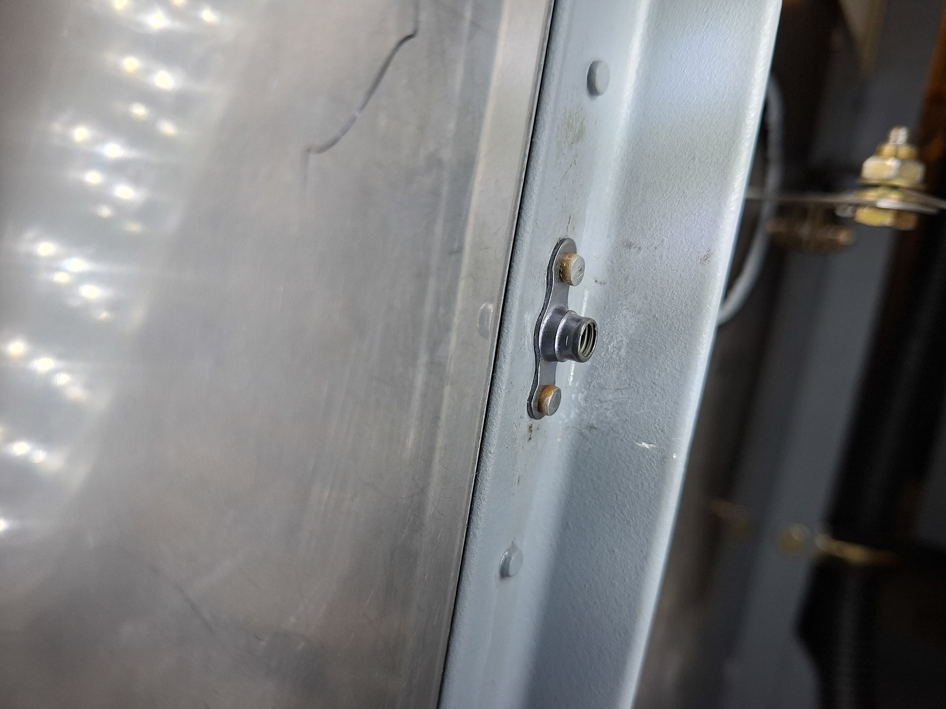
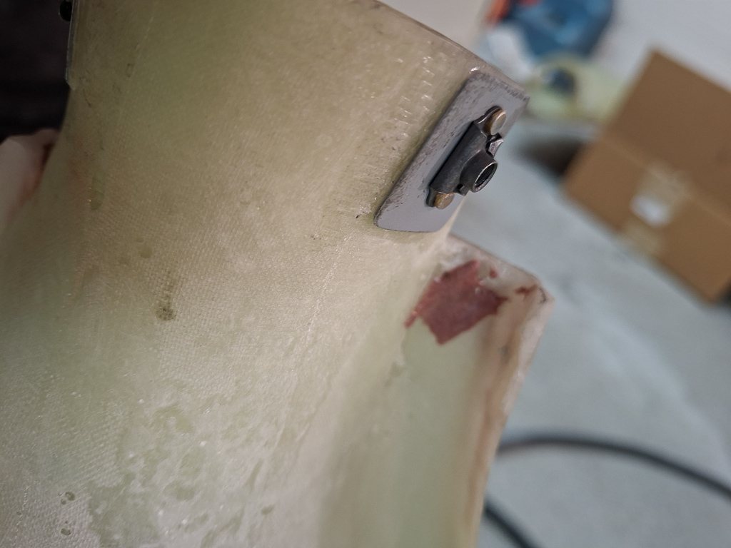
I had some time left and final installed an AN nut and 1/8 pipe plug on the top line of the transducer.
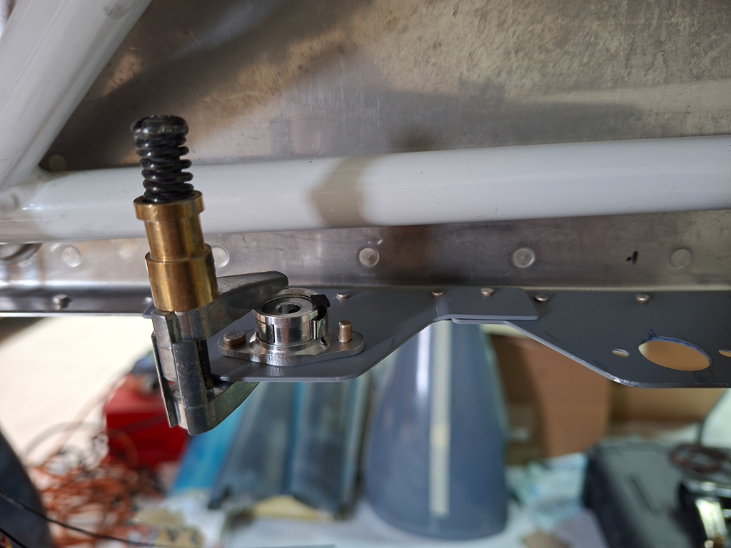
Next I torqued the brake cylinder in place on final install after having applied 3M fire barrier on the cylinder opening in the bottom.
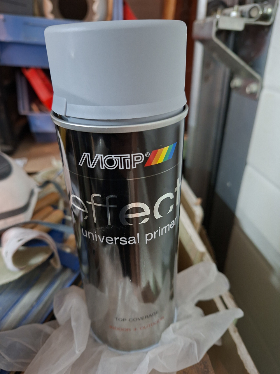
Some small flakes op coating came of of the engine mount near the landing gear nut so I scuffed this up, degreased and used a brush to apply some new primer.
It's a bit messy with a brush but it's a bit overkill to get the spray gun out for these small patches.
Finally re-installed the AN5 bolts and all metal nuts for the landing gear and torqued them. I smeared some Aeroshell 64 grease on the bolt once it was partly in, but not on the threads. AN5 need 100-140 inch/lbs and I torqued them at final value of 135.
Only one more thing to decide before I can hang the engine : the location of the external voltage regulator for the alternator.
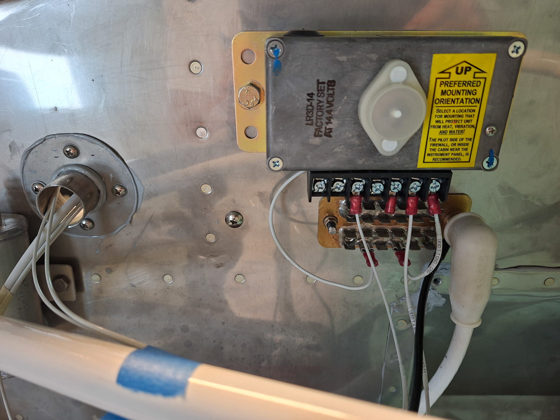
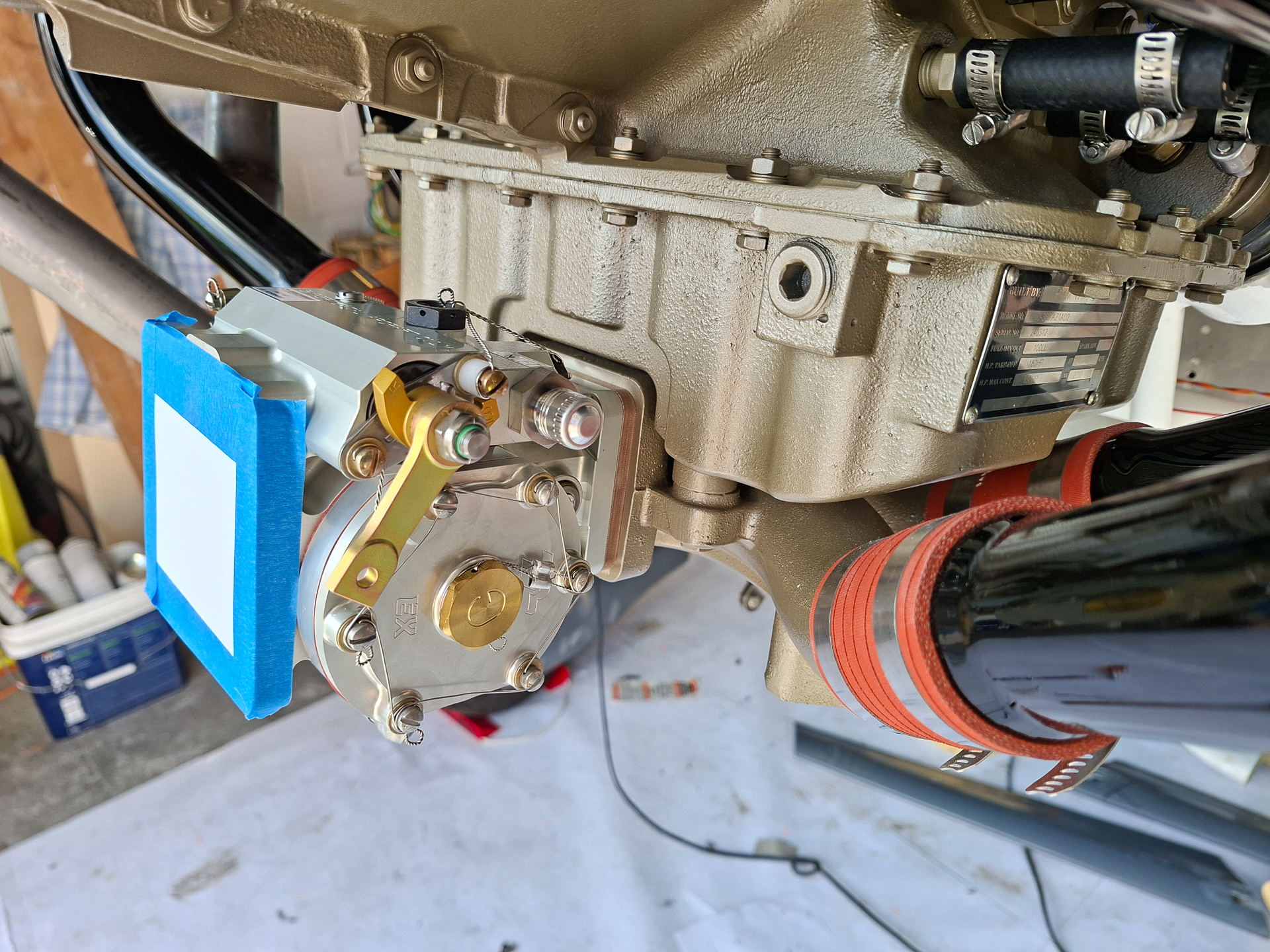
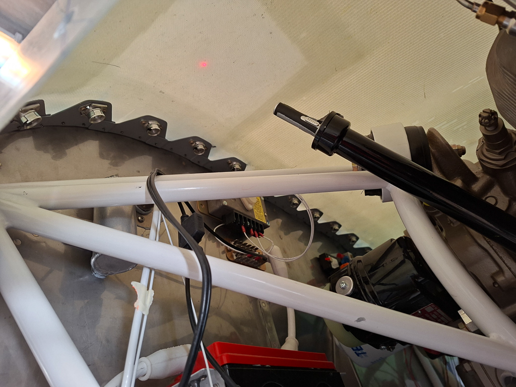
25/07/25 - B&C Voltage regulator installation - 6h
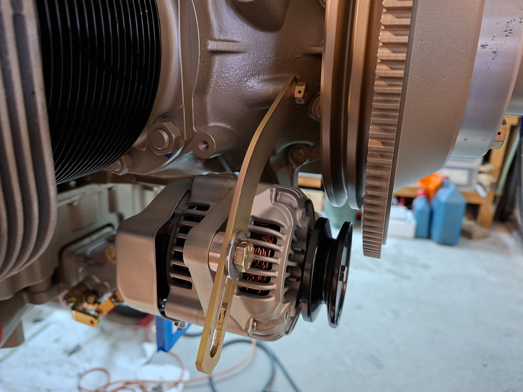
With the engine delivery came a B&C starter and alternator. The alternator delivered is a 60Amps alternator of type LX60 experimental.
The LX60 comes with an external voltager regulator of type LR3D. The voltage regulator constantly monitors the voltage on the main bus (through a VPX pin) and activates the Field line into the alternator. It is the field that dictates how much current the alternator will produce to feed the bus and battery.
As it's an external device, this also means that it needs a location somewhere in the plane. Many debates have been held on the location of this regulator and you basically have 2 choices : either on the firewall FFW side or behind the firewall inside the cockpit sub-panel area. I talked about this with multiple people. I finally decided to hang it on the firewall FFW side. I want it away from the exhaust tubes where the temperature is not too high and my optionally duct some cooling air onto it. My mechanic who will perform my final inspection told me I should not worry about cooling the voltage regulator and that it is probably better to think about cooling the mechanical fuel pump to prevent vapor lock.
My initial thinking was to hang it next to the contactors, below the battery. But the location is not easily accessible in the lower cowl compartment and probably too close to my exhaust tubes.
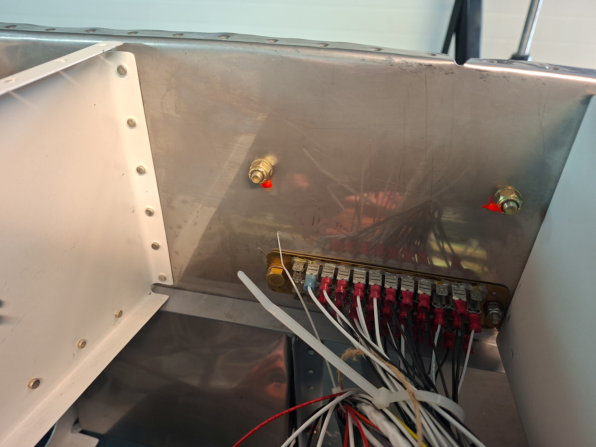
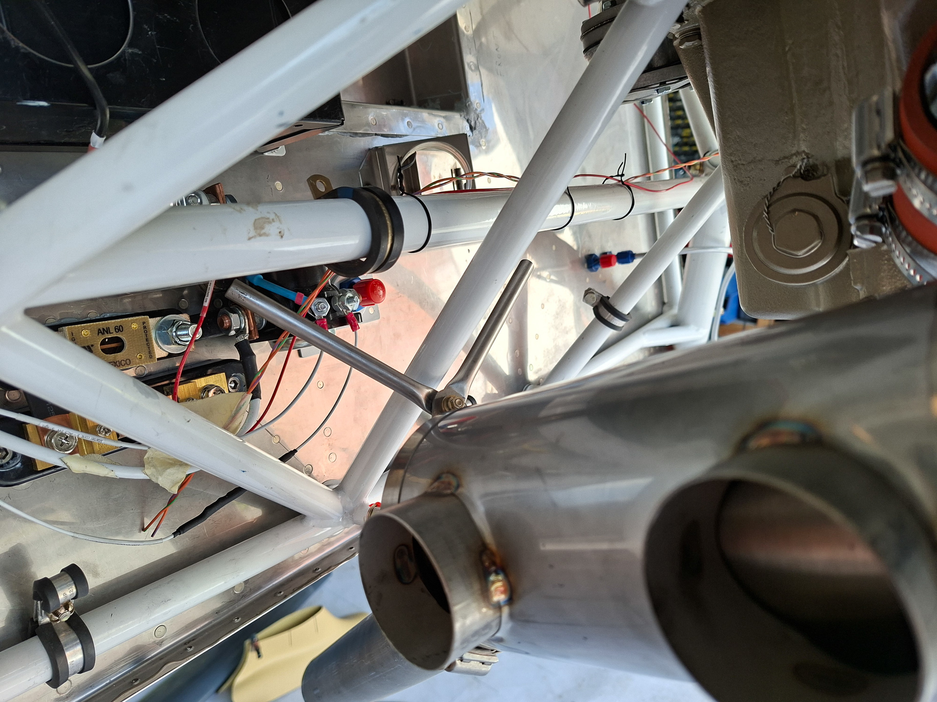
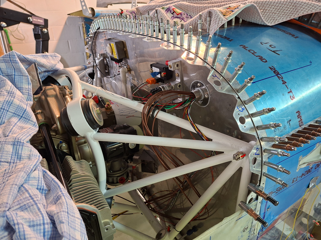
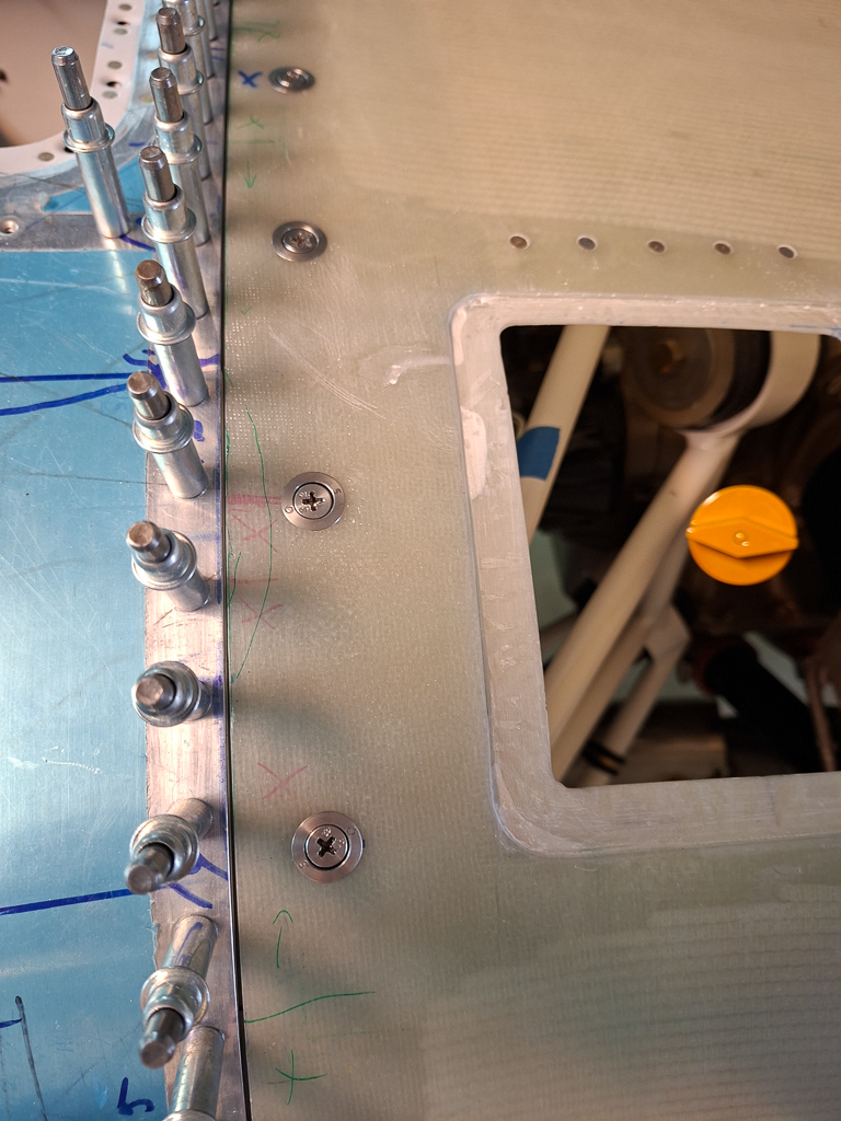
So the next option I see where it wouldn't bother other stuff would be near the top of the firewall above the ground tab block.
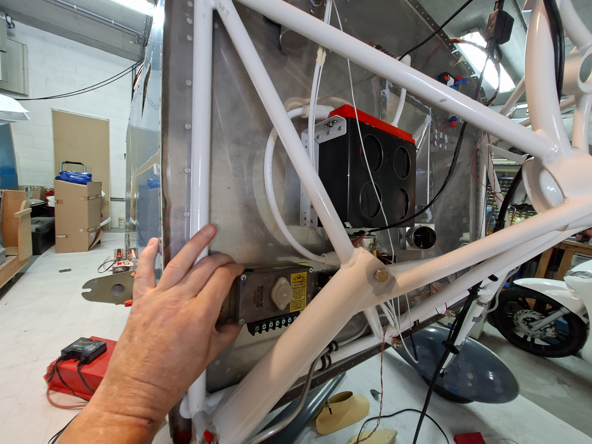
In the picture below, I drilled the holes and installed the bolts. The attach tabs for wiring on the regulator are far enough forward from the ground tabs so there is no interference.
On the inside the bolts are high enough not to chafe anything and I torqued them to spec.
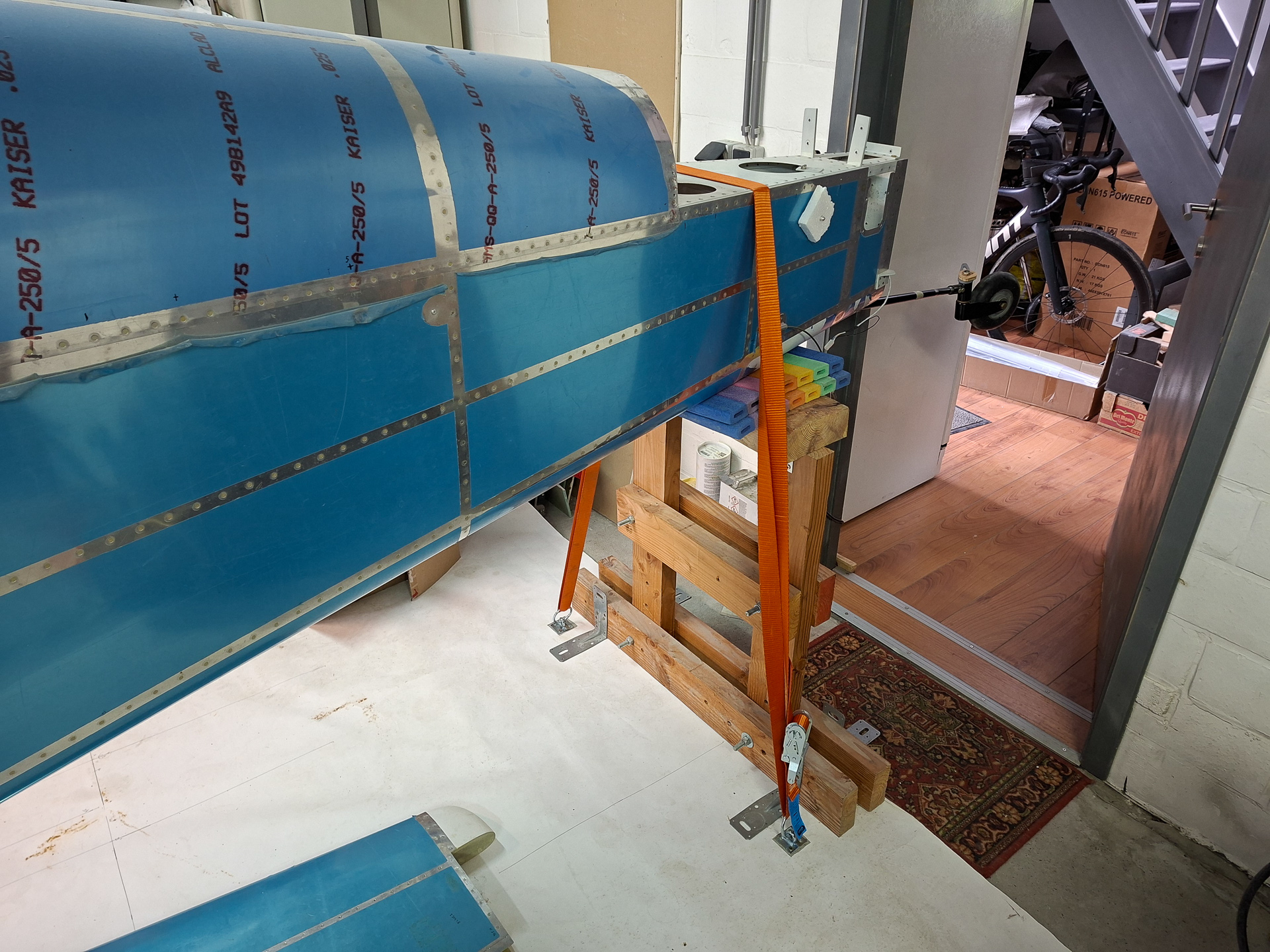
I am planning to hang then engine soon so I took some time to install hooks in the garage ground so that I can safely hold the back of the airplane down when the heavy weight is added to the nose.
Next I started wiring couple of wires on the regulator. Installed the 2 GND wires (one on pin 7 and one from the regulator case stud).
Then ran a wire from the ALT field pin on the VPX to the pin 6 "Bus Field Supply input" on the voltager regulator. On the VPX, this is a dedicated pin J12-11 with 5 Amp breaker. It is switched on when the "ALT field" switch is switched "on" on the panel. The other wire is the Voltage Sense input wire at pin 3. This measures voltage on the main bus at the VPX input pin (in my case J12-8 protected by a 2 Amp breaker) .
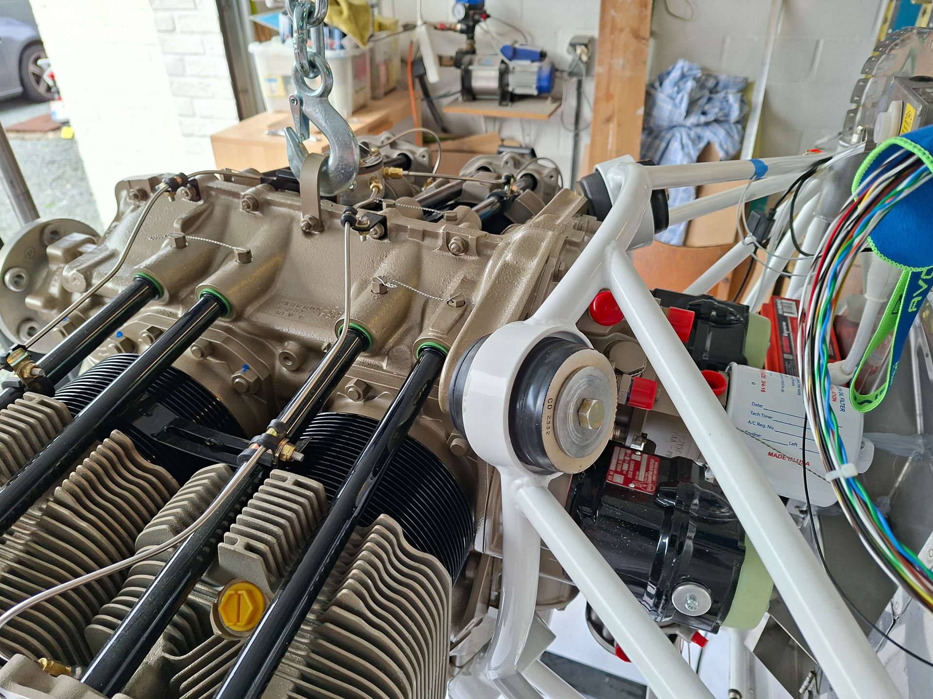
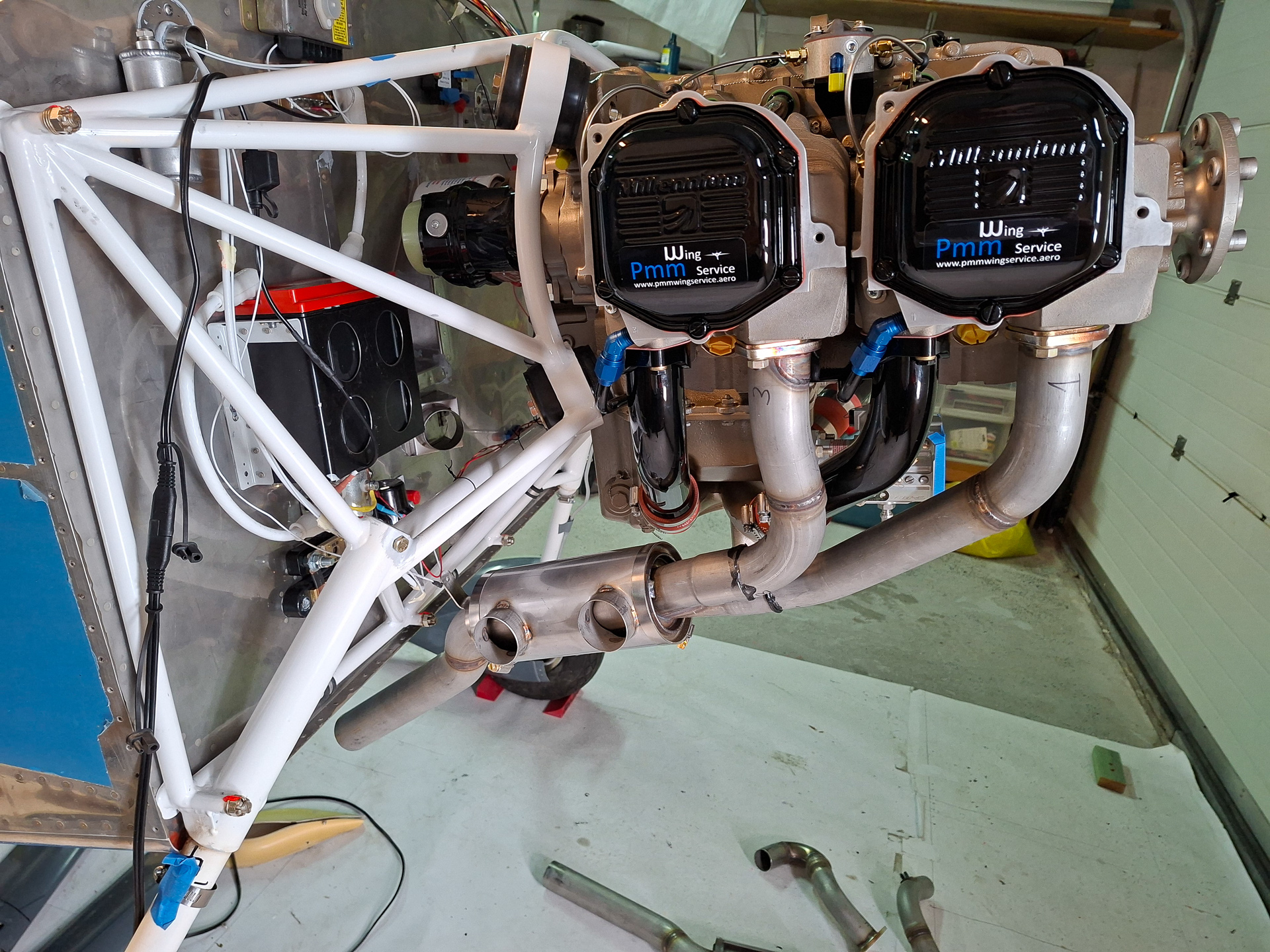
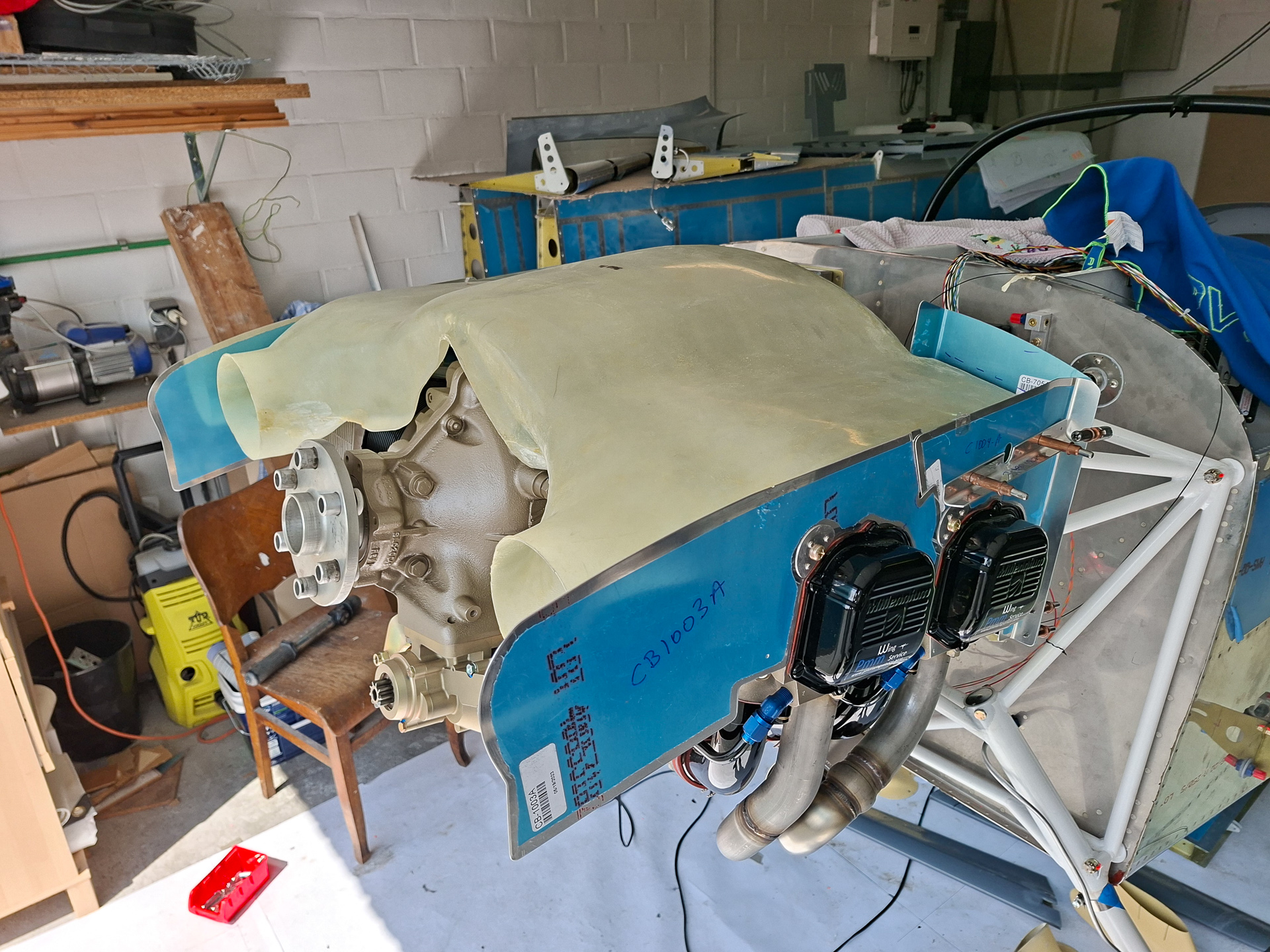
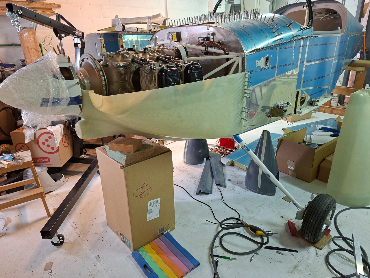
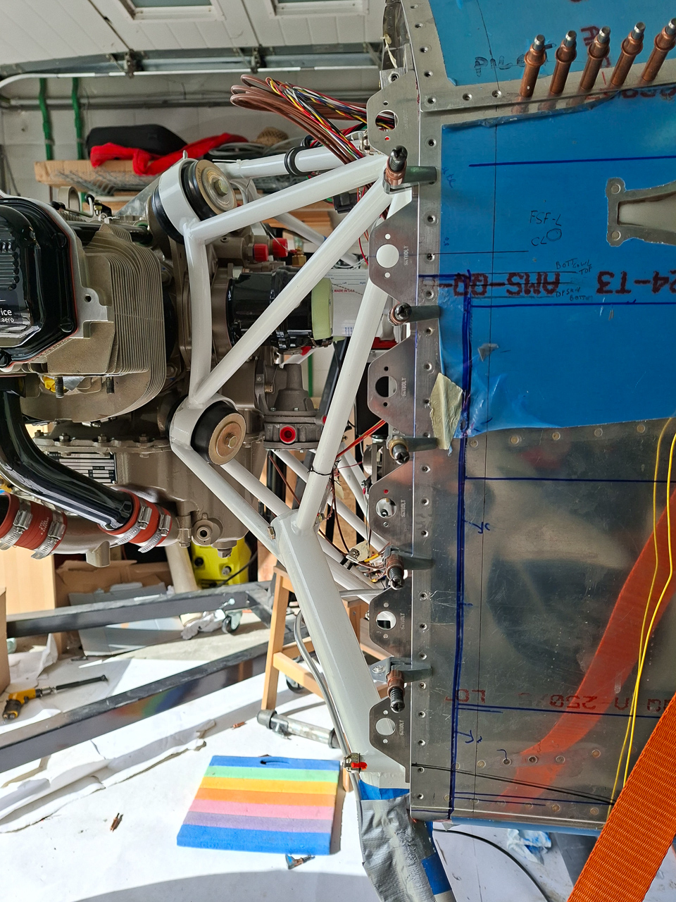
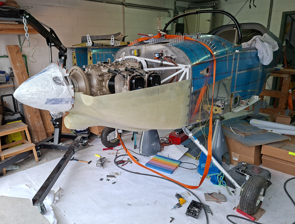
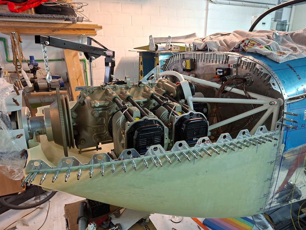
28/07/25 - Hung the engine ! - 6h
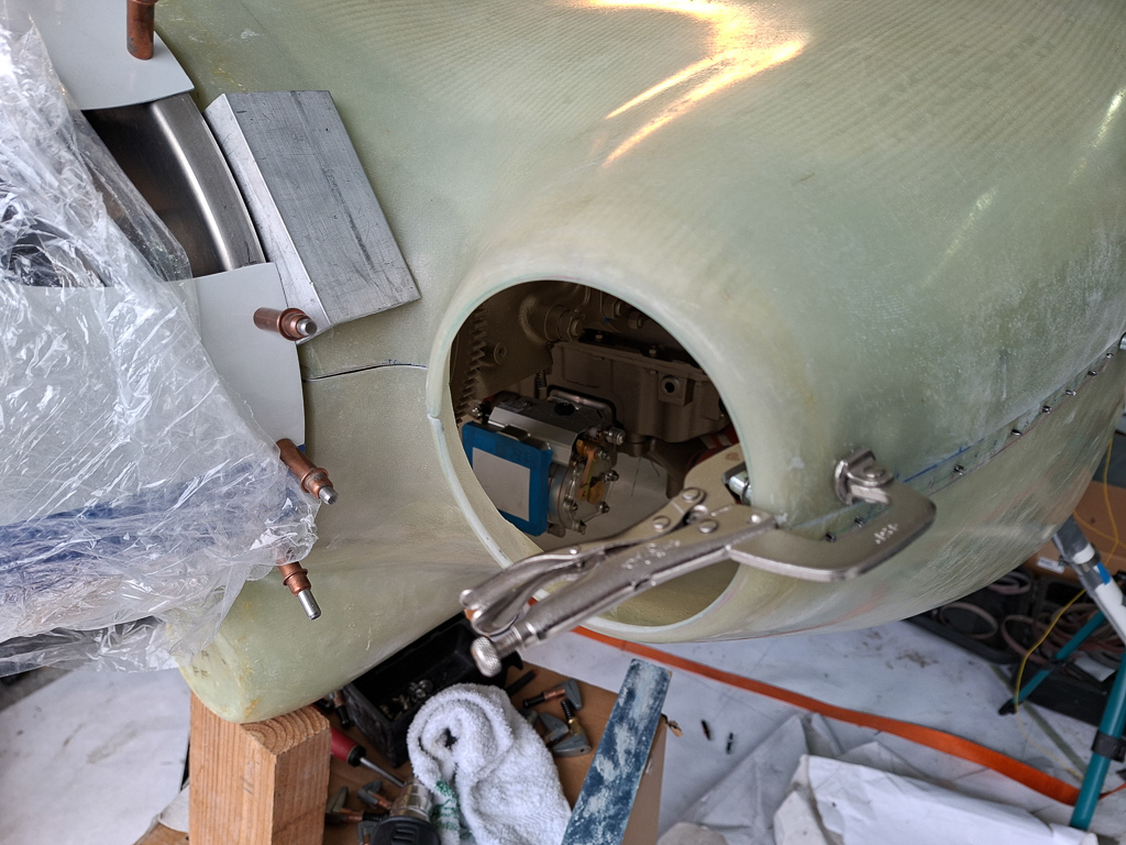
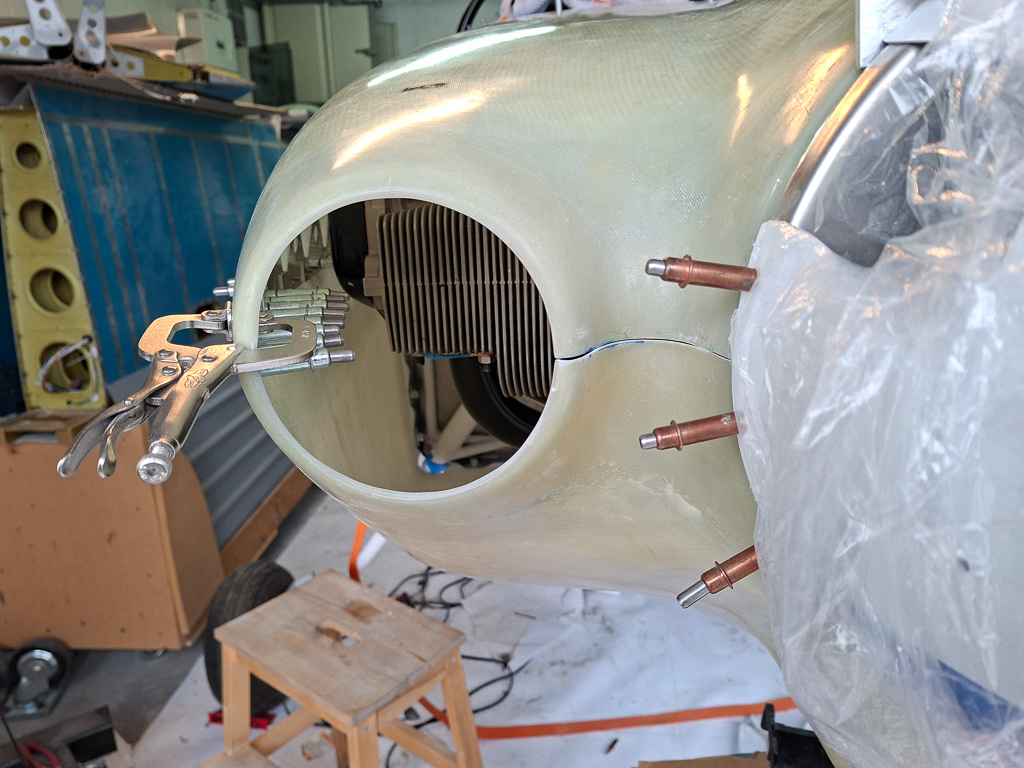
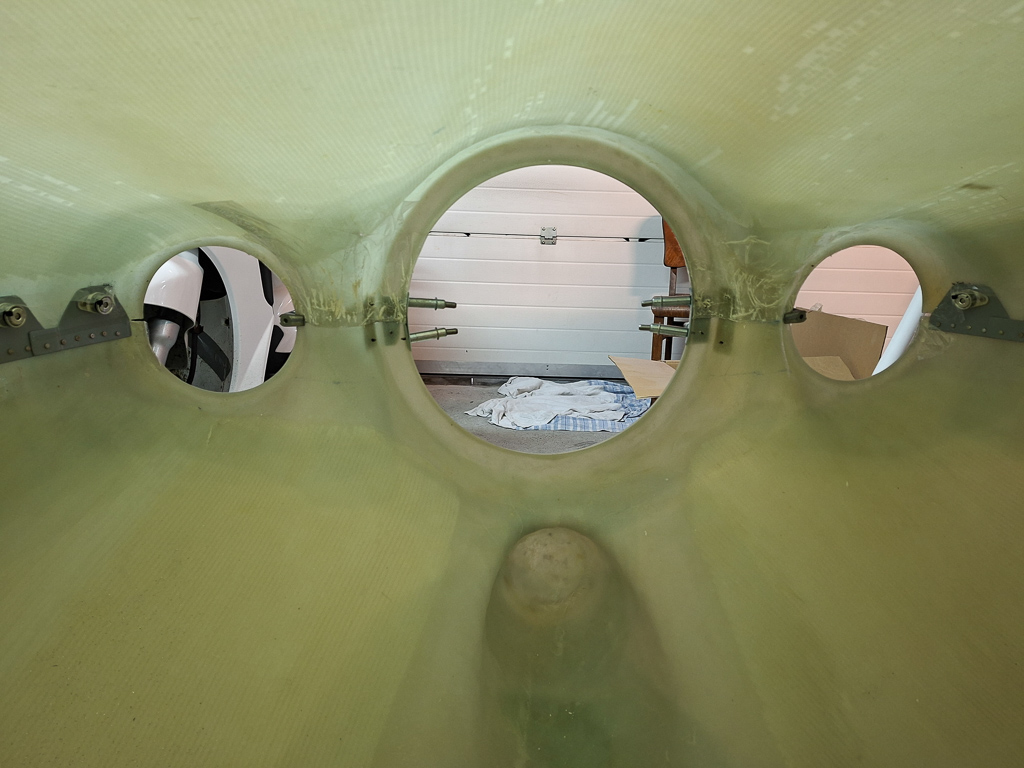
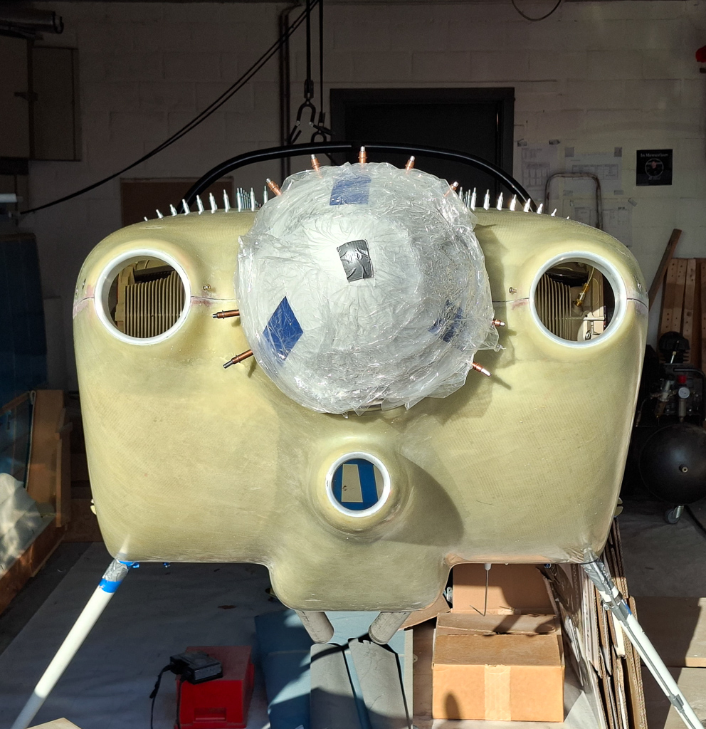
Milestone day ! This is one of those days that you know mark the timeline of building your airplane. The moment you hang the engine in the engine mount. After many days of thinking about missing any things on the firewall, I came to the conclusion that this is the right moment to hang the engine and move on to the firewall forward work. There are some more things I need to do on the firewall, but it's not possible to be sure about the exact location to drill large holes in the firewall until I can actually evaluate the position with the engine in place. i'm thinking of the mixture and throttle cable and alternate air cable. Other than those, I'm pretty sure everything on the firewall is in place.
The same thinking goes for the rear of the engine case. Make sure the 45° restrictor fitting for the oil pressure is mounted in the engine case prior to hanging the engine. It's almost impossible to install this once the engine is on the engine mount. Mine was already installed by PMM during engine assembly. While you are at it, also install the other oil cooler fittings in the engine case (in and out). These can also be done later but it's easier now.
First step was to remove the safety straps that held the engine to the wood pallet that was used for transport. I want to keep track of how this was done as this engine is a brand new engine that has not yet been on the test bench. When all is ready, I will need to unhook the engine and bring it to PMM Wingservice to have it running on the test bench for a first time. This has the disadvantage of extra work on removing the engine and all connections again and having to do it again after it has been run. On the other hand, the major advantage is that I do not have to worry about corrosion and idle time of the engine as it has not yet been running. The cylinders are as if they would be in a stock location on a bench waiting for an engine. There has been no movement of the cylinder heads on the cylinder walls and everything has an oil film on it as delivered from Superior Air Parts. Whether building takes me another 3 years or just 1, it won't matter. I'm gladly willing to take that extra work knowing there is no pressure.
The engine was protected well on the front and rear crankcase and supported in the front under the front with some wood block supports. I'll have to keep all this in stock so that I can re use it in the same way when I bring the engine back to PMM.
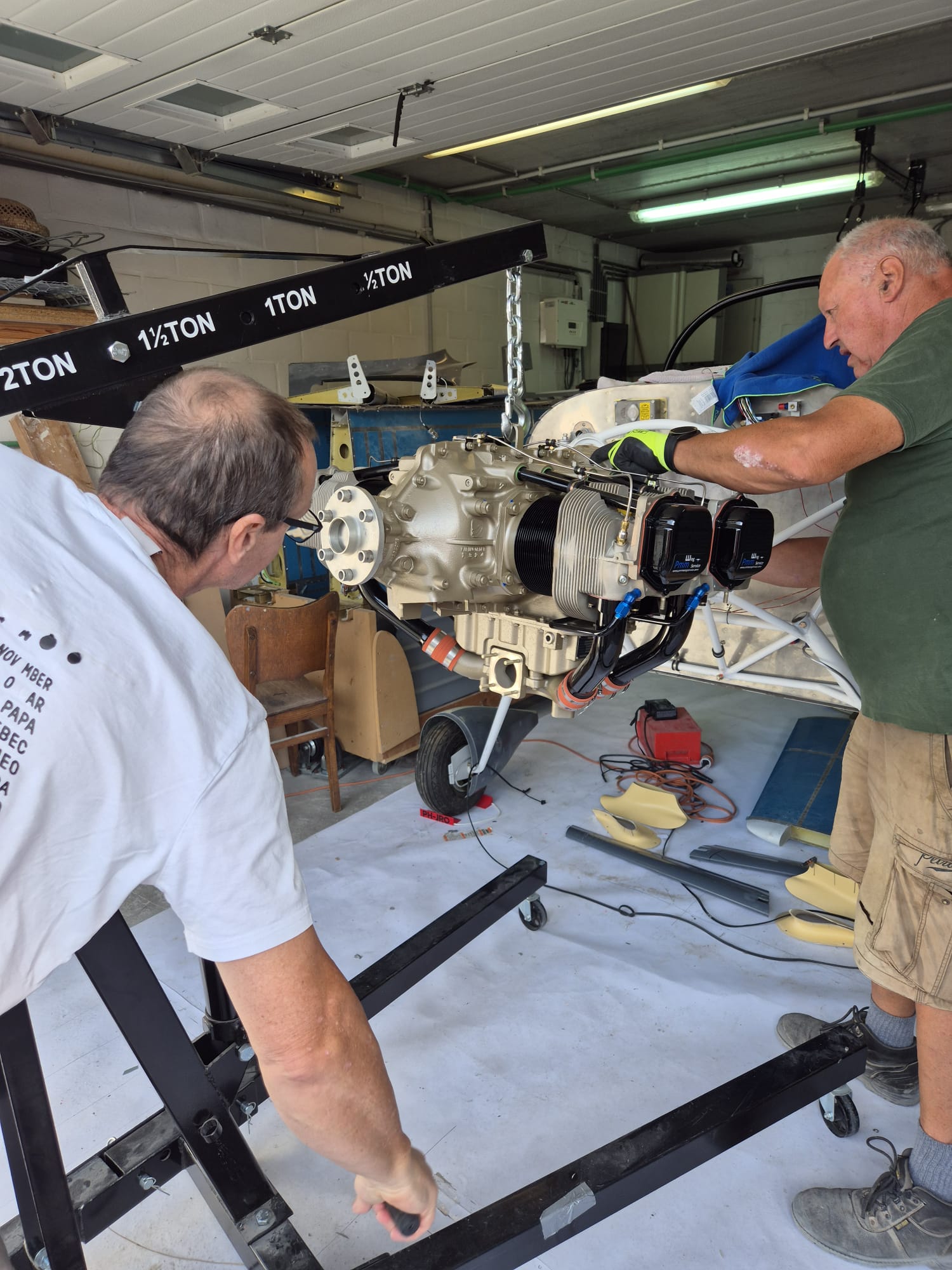
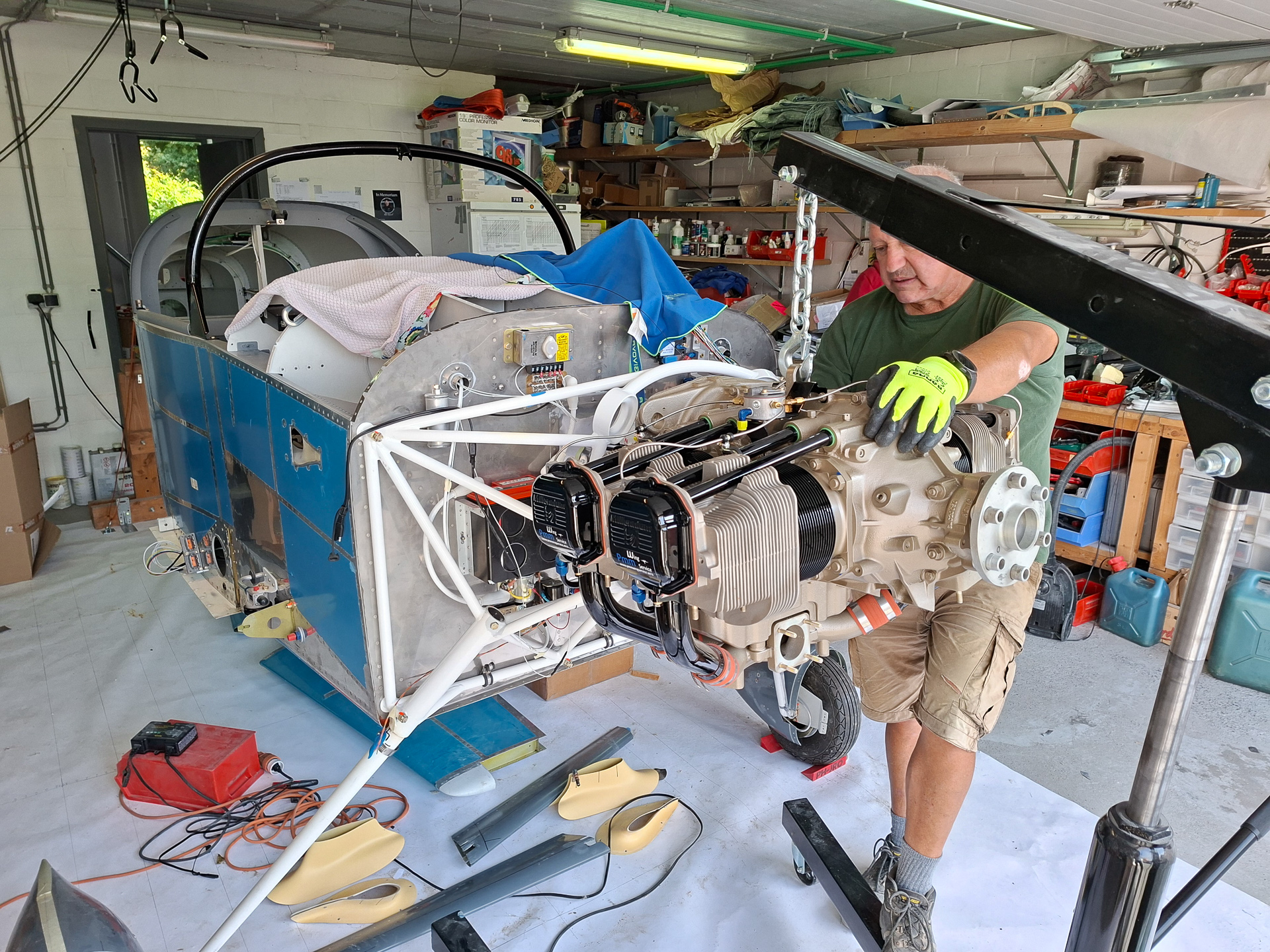
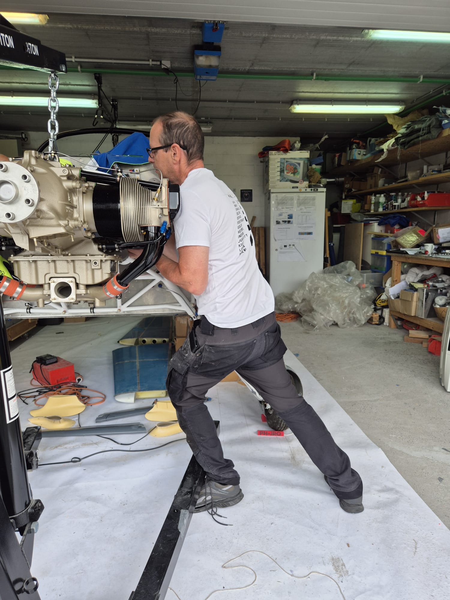
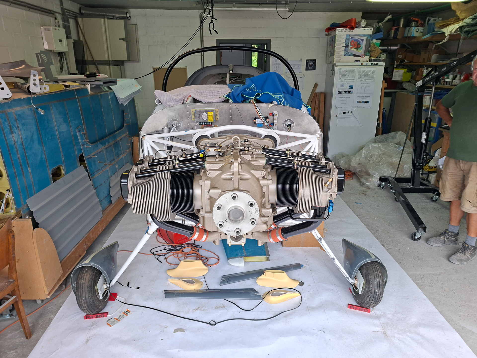
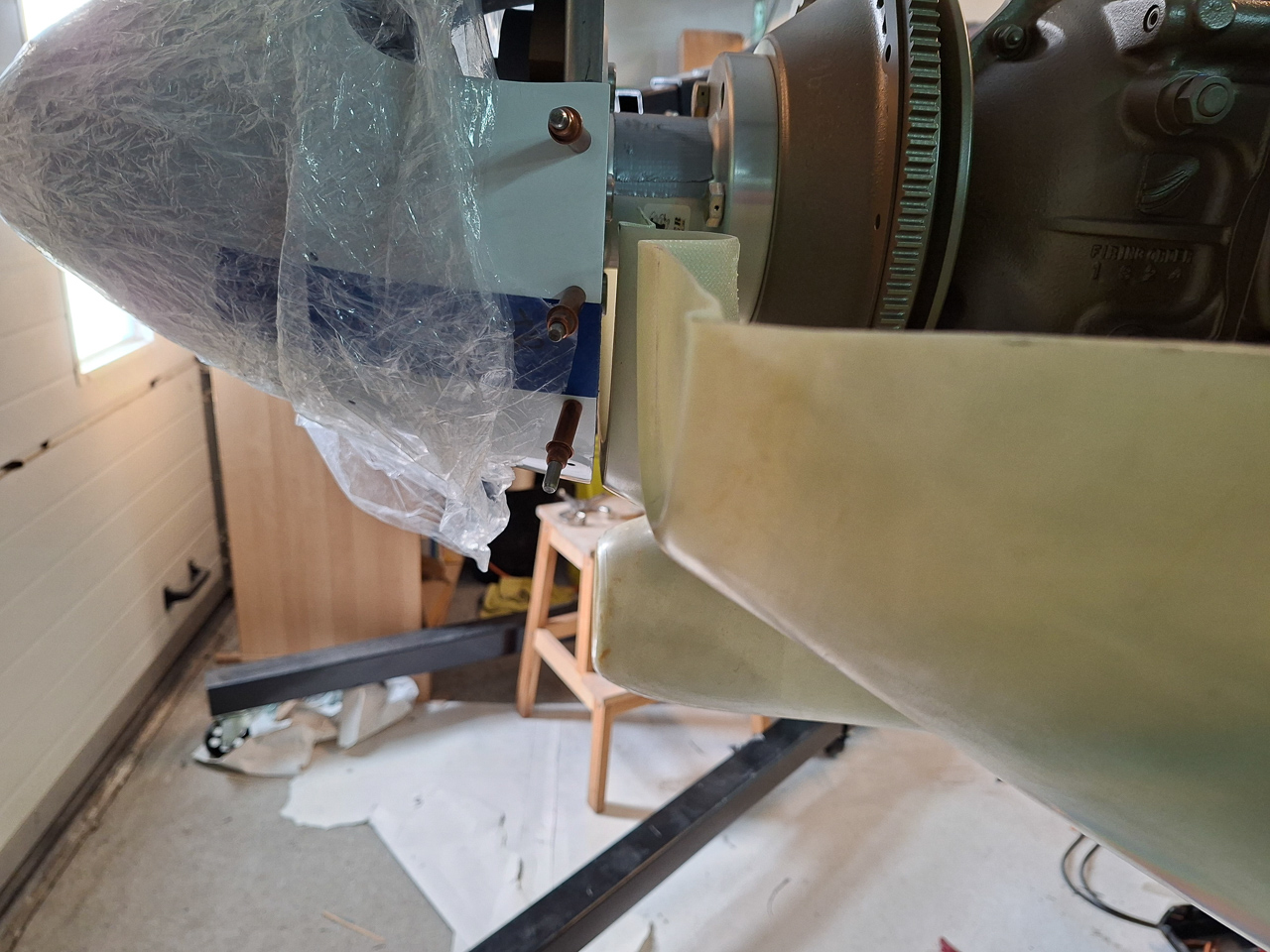
Using the engine hoist, we pulled it up, removed the pallet and moved it over to the front of the airplane. Alain helped me on this task to keep the engine in position. It's best having some extra hands around when you do this as the engine is heavy and the bolts are not always willing to go in as easy as you think it would.
The last part of the moving is the most critical as you don't want your magneto's or fuel pump to bump into the engine mount. Having one person moving and another one guiding the engine is no luxury.
Also notice I leveled the airplane in flight mode. This is much easier to position the engine than if it would be sitting on all tyres which would require you to position the engine at an angle. This leveled way makes it much easier.
I found some documentation online from someone who did this before and described the process. I studied this carefully and upfront, had a close look at the barry mounts and dyna bolt set. You can read it following this link https://www.myrv14.com/buildlog/20150917/Engine_Hanging.pdf. Vans Aircraft also has some drawings available which are not part of the standard plan set that you receive with the kit.
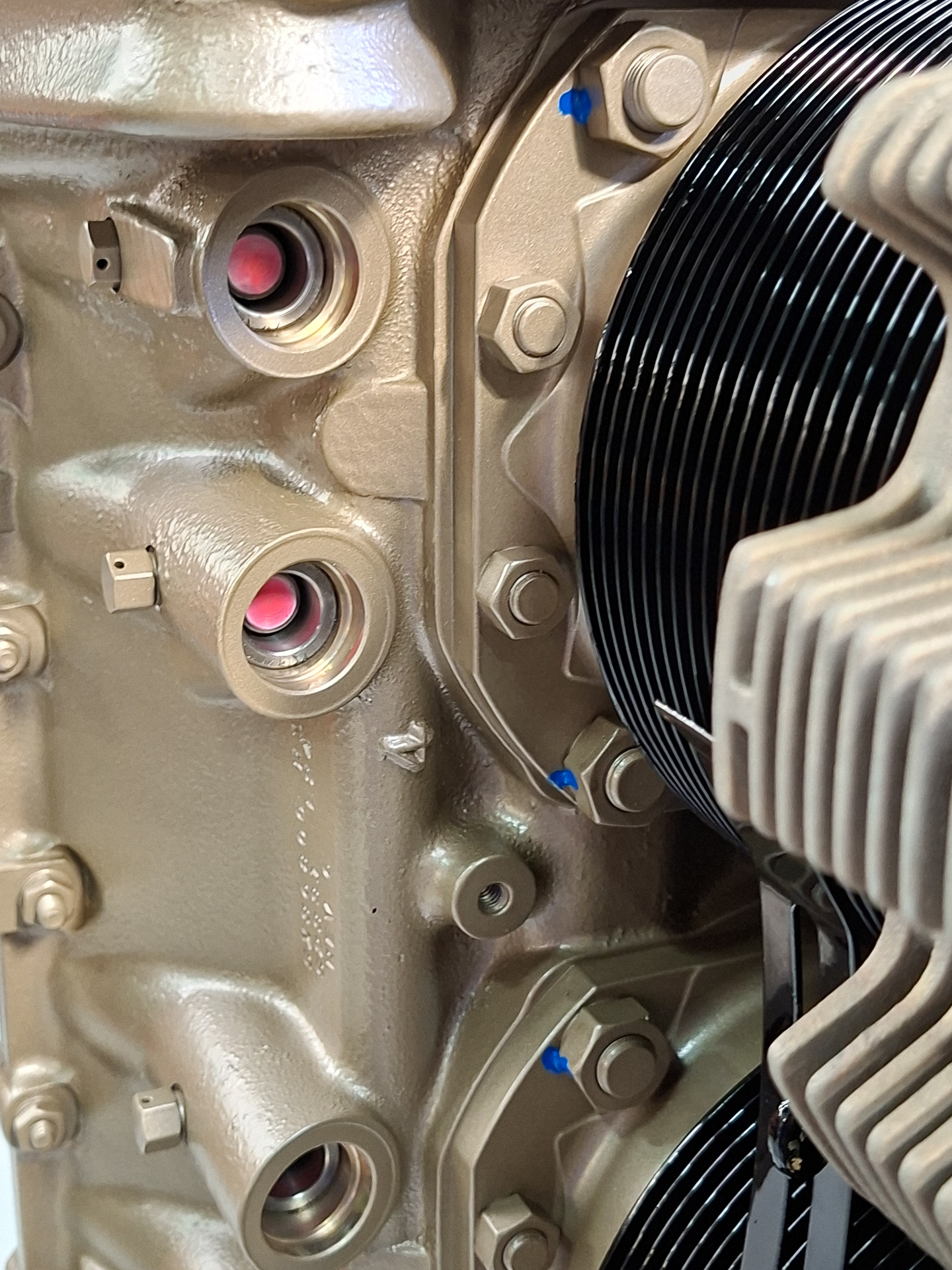
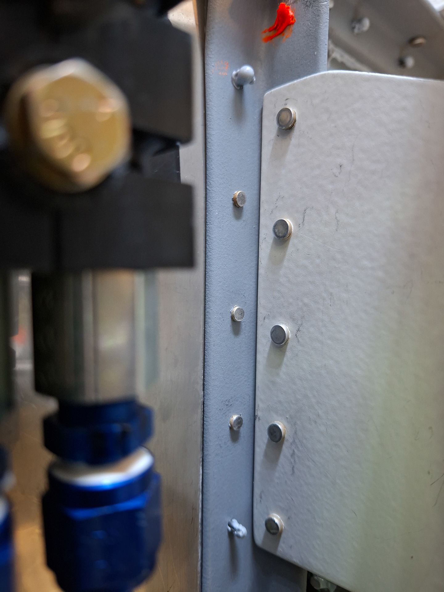
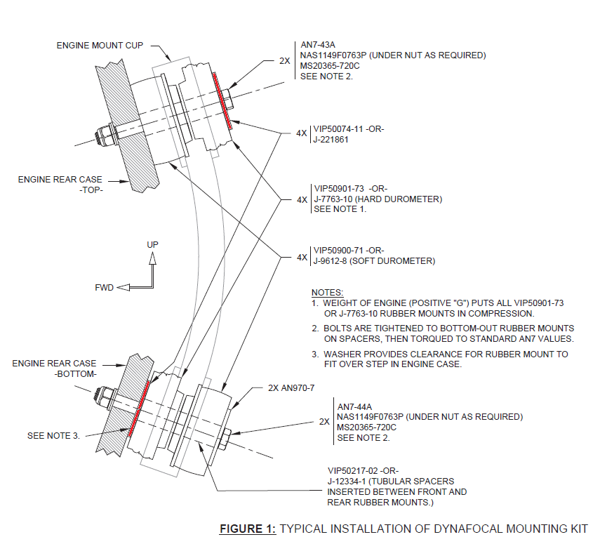
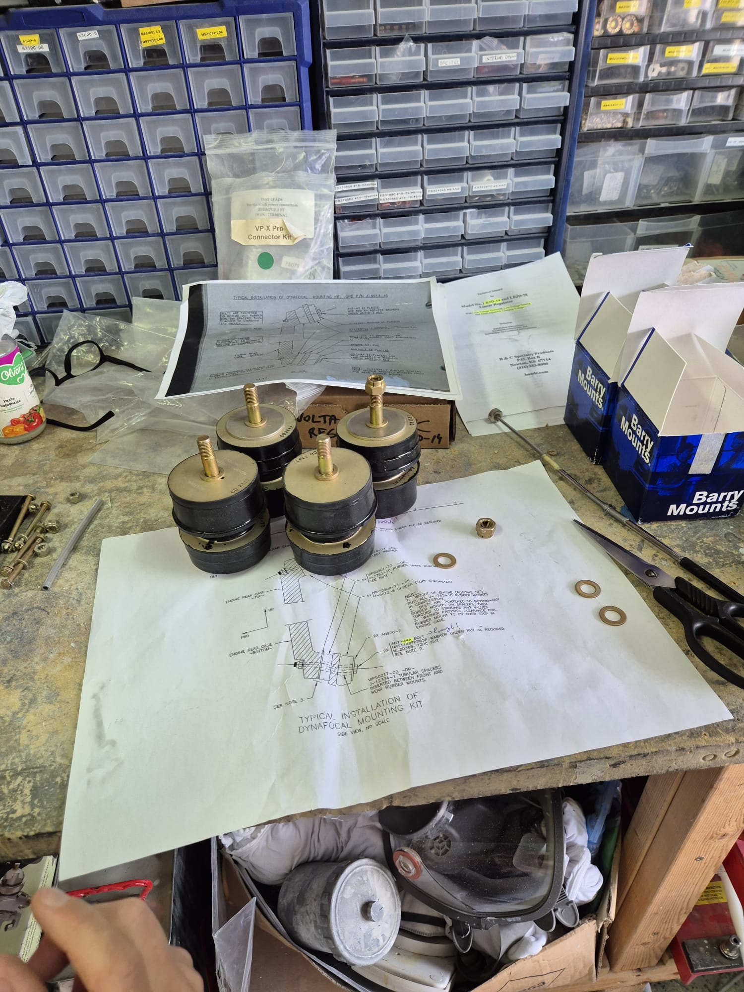
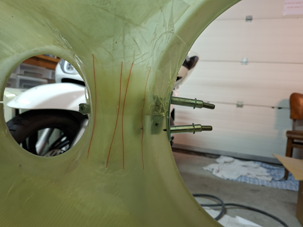
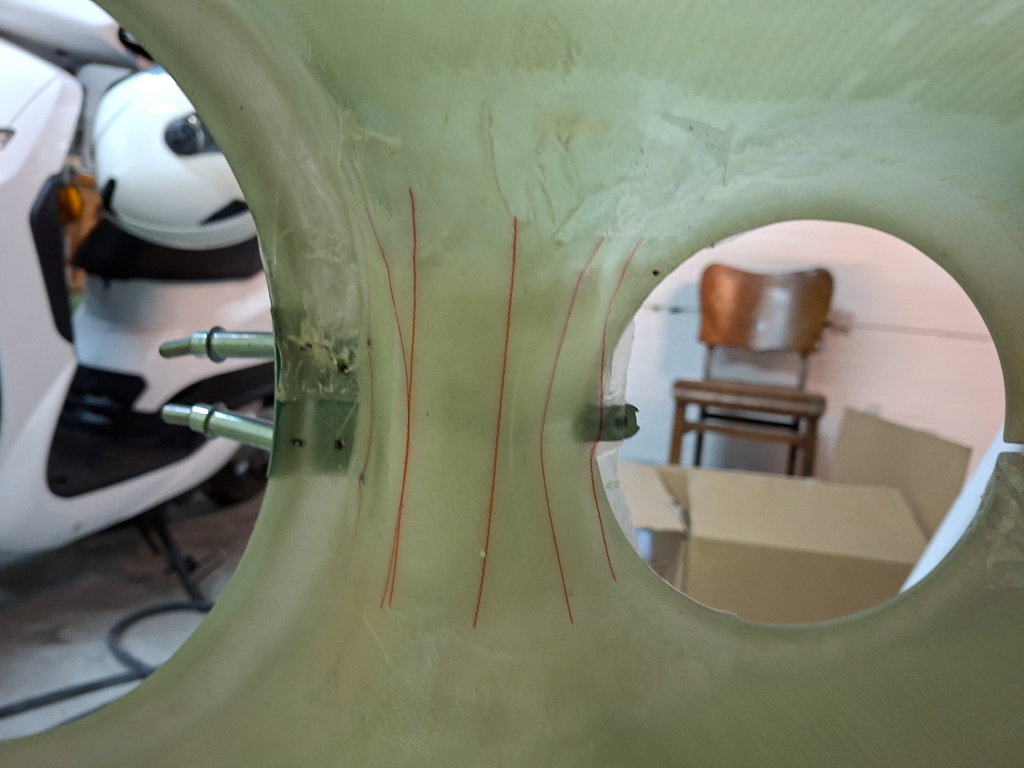
Study the plans carefully, the barry mounts have to be positioned so that the engine rests on the compression side in the bottom and the compression side in the back on the top mounts. The compression barry mounts are the ones that have a step in the rubber. The non compression ones don't have the ribble on it and look like plain rubber. If I remember well, the non compression ones also are a little larger. Also take care that the washers are in the correct locations. The barry mounts come with one big washer in the box. It's good to assemble the order of all this before starting to move the engine and have thing prepared well. I colored the position of the large washer red in the picture above.
There are 2 lengths in the dyna bolt kit. 2 x AN7-43A and 2 x AN7-44A. The longer ones go on the bottom side, the shorter ones go on the top. The difference is not much more than the length of one of the washers.
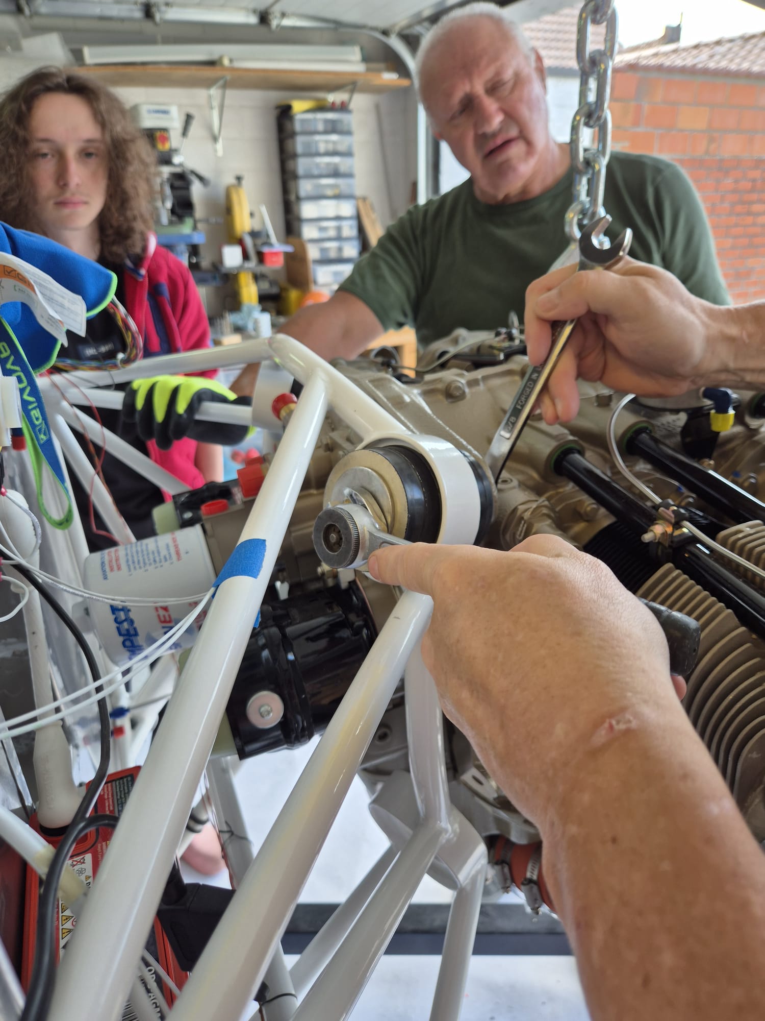
Start with the 2 top bolts. The first one is very easy... tighten the bolt but don't torque it yet, you'll probably have to loosen them again working on the bottom bolts. You do need to tighten the first so that the barry mounts compress allowing the other hole to come in line with the engine case. Remember this is a dynafocal mount, the bolts point inwards. If the bolt is not tightened enough on one side, it's impossible to insert the second one. As you tighten the bolts, the barry mounts compress and also position themselves in the engine mount. That's important.
What I found very annoying is that you can't put a socket on the bolt head as the engine mount is in the way. I used an extension on the wrench but that didn't make it easier.
The engine sometimes needs a bit of persuasion to get it in position :) Although I don't think this did much. Found out later it's more important to tigthen the other side and use the engine hoist to lower or lift the engine a bit in order to get a bolt in.
The large washer goes between the compression mount and the crankcase as a spacer for the bottom mounts. On the top mounts, I have put that washer on the compression mounts under the bolt head as you can see in the image below. The image has both top bolts in place and tightened.
From there on, things went less smooth and it took about an hour or 2 before I got the last bolt in so I did not take any more pictures until it was done.
I'll try to describe the further process I took.
As both top bolts were tightened, I lifted the engine a bit using the engine hoist. This allowed me to slip the barry mounts between the case and the engine mount. Don't forget the large washer between the barry cookie and the engine case. Don't forget the compression side of the barry mounts is against the engine for the bottom mounts. Then I lowered the engine again and after some wiggling I was able to put the 3rd bolt in. I did have to loosen the top bolts a bit though.
The fourth bolt is the most difficult one. Looking with a mirror through the hole there was no way the bolt would go in. After a lot of moving up and down, I finally discovered my problem : the washer between the barry mount and the engine case was not aligned and the pressure on it is high enough that it makes it hard to move it. After lifting the engine a bit and tapping on it, I could get it more or less into place. A second trick I used was to take an old bolt which was smaller in size and grind down into a guide pin. Once I could slide that smaller bolt in, I was able to wiggle it around in order to get that washer and the engine hole into alignment. I put some grease on the final bolt shank and finally was able to put it in with only very light tapping of a rubber hammer.
I was feeling relieved as I bolted the final nut on that fourth bolt.
As final step, I torqued the bolts. These are AN7 which take 450 - 500 inch/lbs. I used the middle value of 480 inch/lbs. The engine will still need to come off as mentioned earlier but the position of the engine is very important when installing the cowling so I torqued it to the final value.
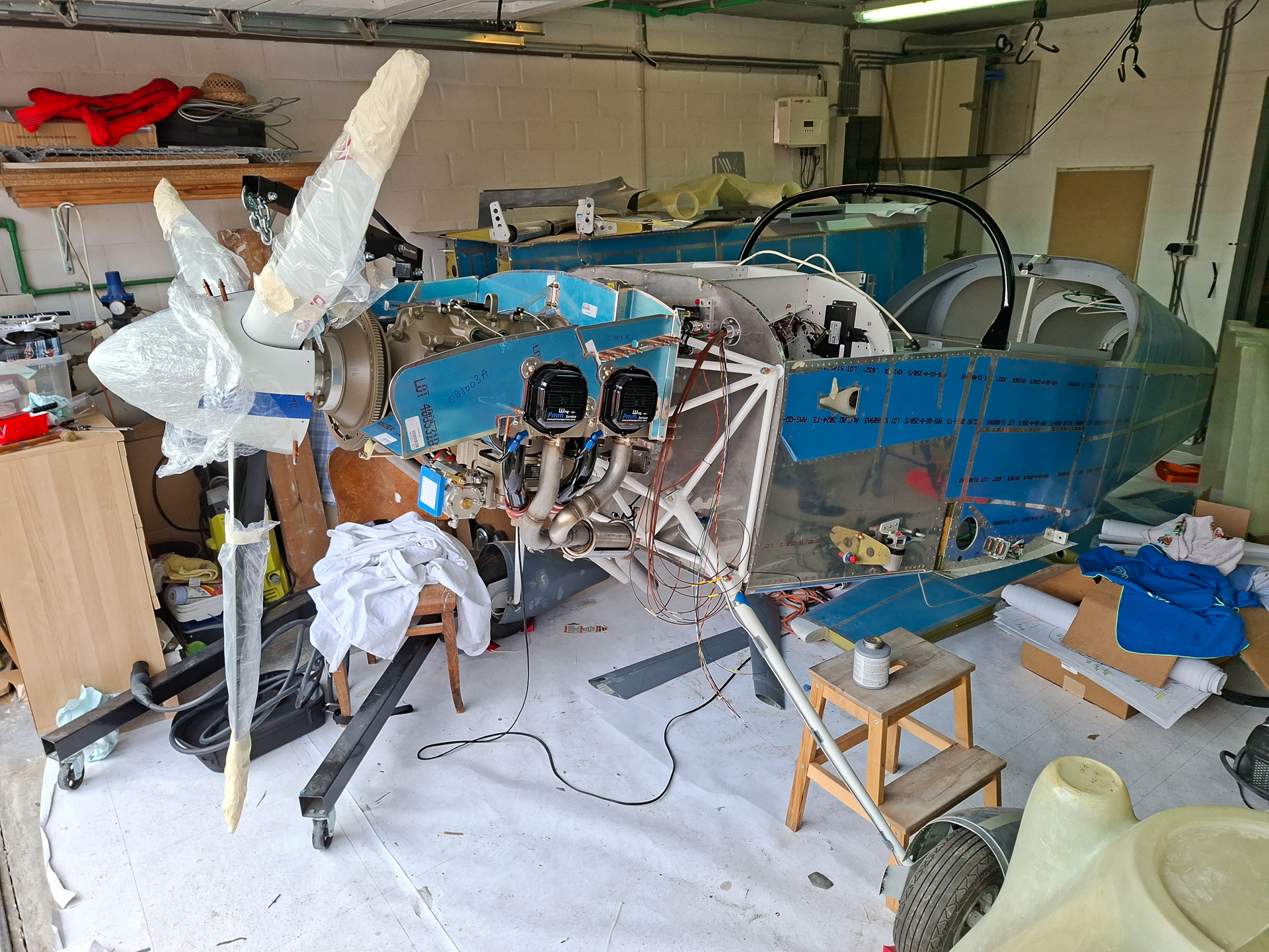
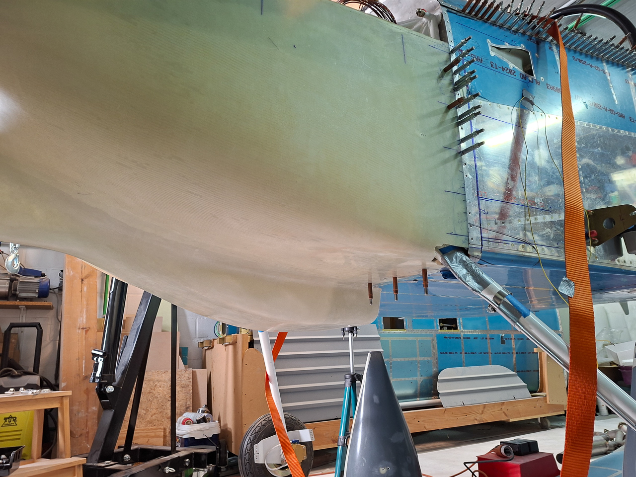
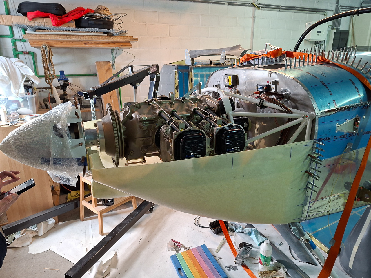
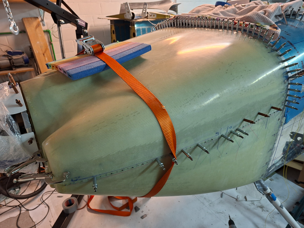
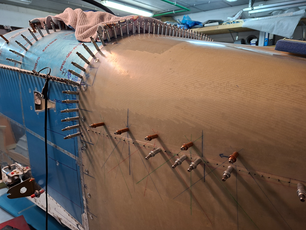
Took some pictures of the plane with the engine in place. This surely is a big milestone and is a "feel good" moment during the build.
Happy camper...
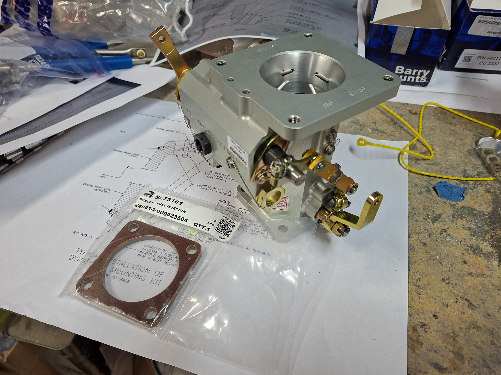
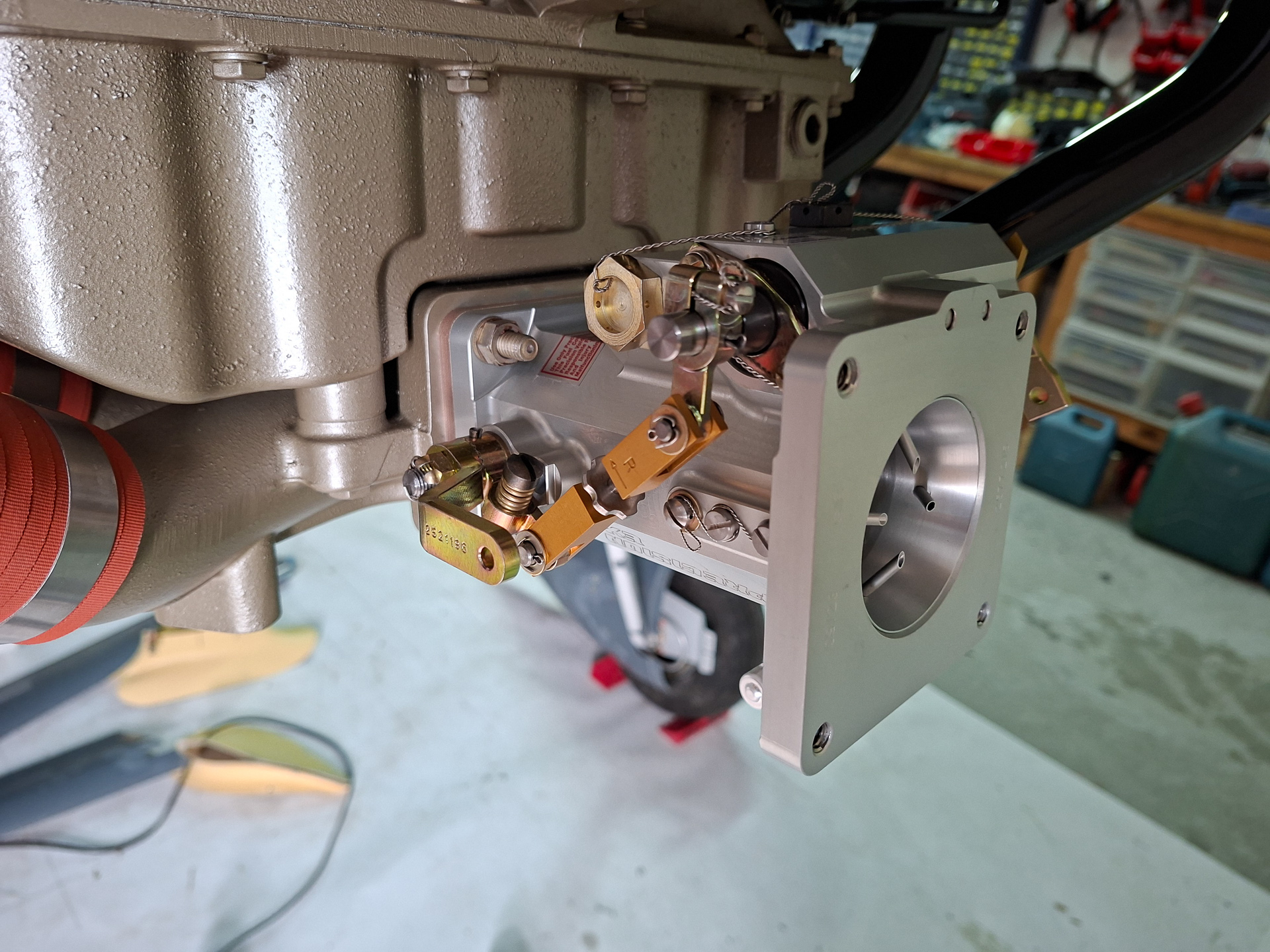
As I had some time left, I took out the fuel throttle body. This comes with a plastic spacer.
The orientation of the throttle body was a bit of a mystery at first but soon figured out what side was the throttle lever and which side the mixture. In the image below I installed it on the forward horizontal induction air intake at the cold sump of the engine. In the image below, the throttle lever is the gold colored arm.
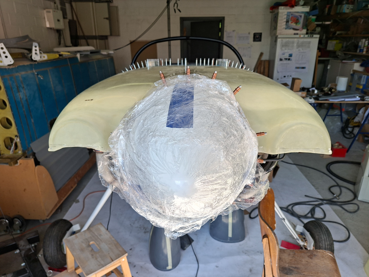
Finally I covered the intake with some paper and masking tape in order not to get foreign objects entering the engine.
End of a productive day was off course celebrated with Alain with a good strong Belgian HQ beer.
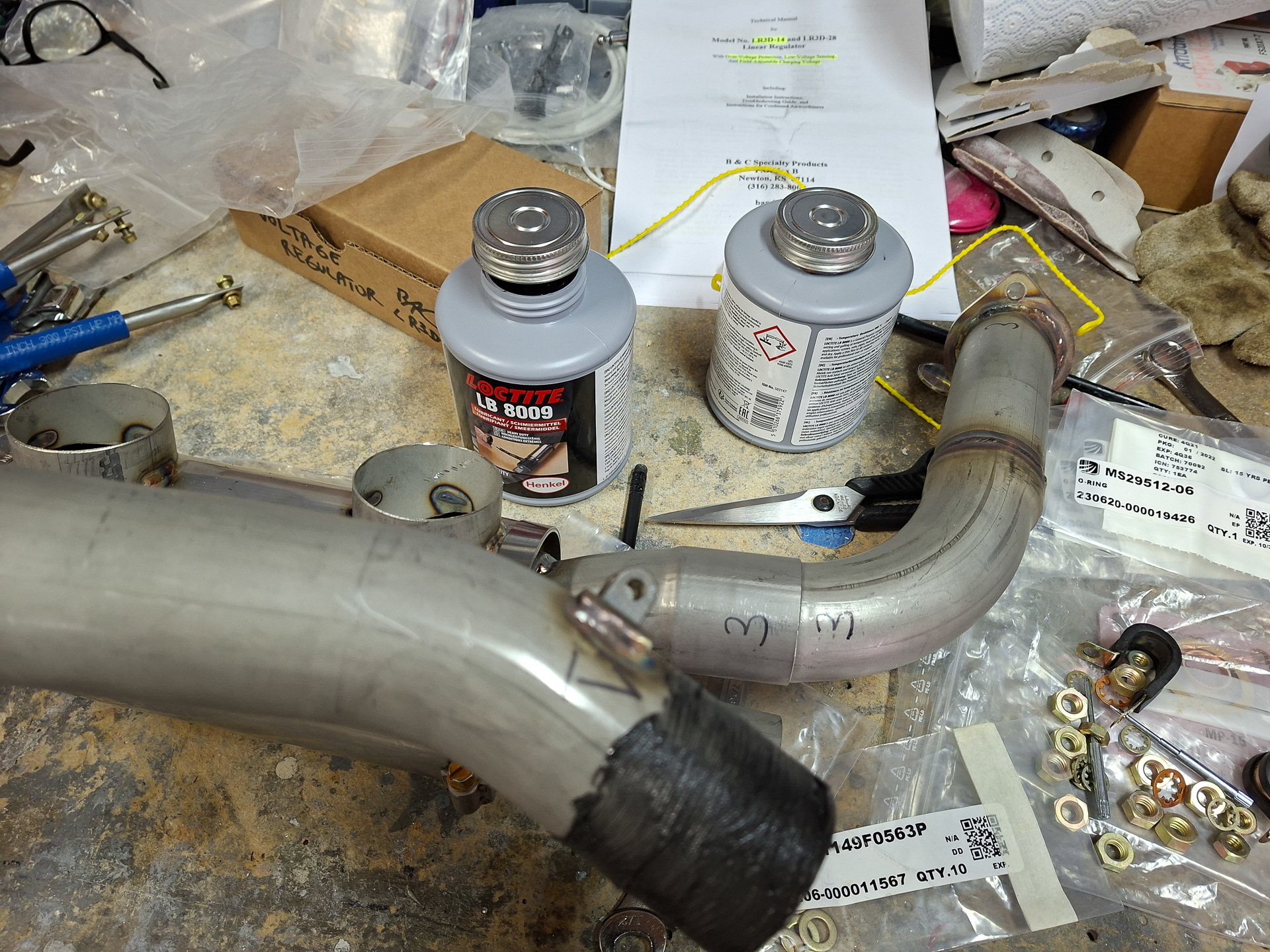
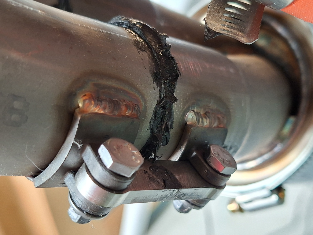
30/07/25 - Exhaust test fitting - 3h00
Next day after hanging the engine, I took out my brand new 2 in 1 Vetterman Exhaust pipes and puzzled them together.
I have chosen for the 2 in 1 side by side system including dual mufflers. I had a long conversation with Clint from Vetterman as he first mentioned that the dual muffler system with a Superior engine would not fit inside the Sam James cowling. This is actually correct but I visited an NVAV meeting in Breda earlier in this year and talked to Joop St Jago who also has the same engine and did install it in a Sam James cowl. He had to cut out two rectangular shapes from the cowl and made some custom extension for it. A small bulge that is hardly visible and has little or no impact on performance. In Europe, noise abatement is a big issue in many airports. Although an RV7 is not required to have a noise certificate (aerobatic) , it's probably not a good idea to rely on that. It won't help a lot if you are taxed on every airport at the highest noise cost (yes in Europe you pay more if you make more noise ***sick*** ). And it also will not help if sensitive airports don't allow you in because you don't have a certificate (the airport I fly now does not allow airplanes without noise reduction system/mufflers). So for all this, I decided it's better to ask for the dual muffler system and cut up my nice Sam James cowl.
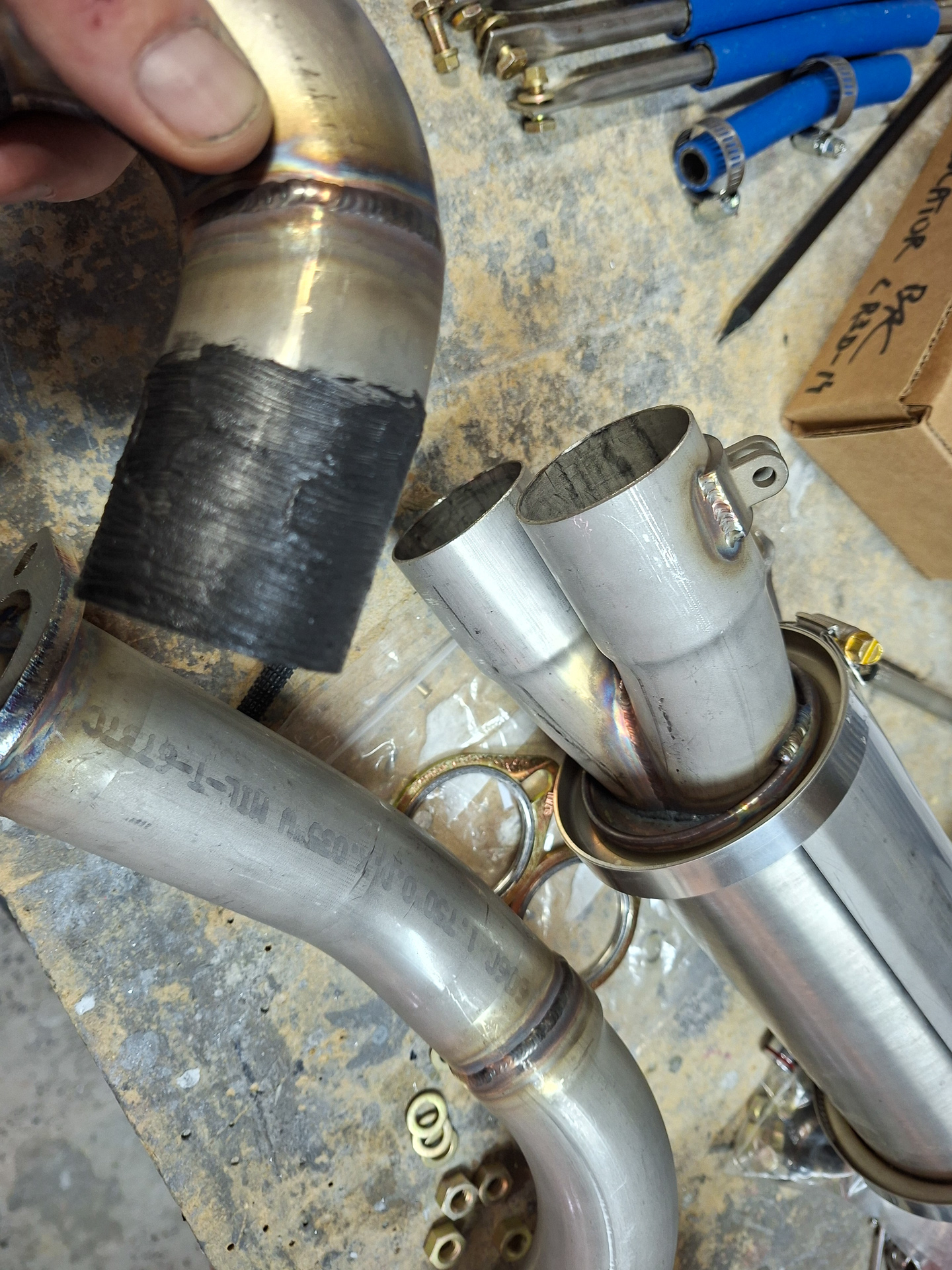
The installation itself is quite self explanatory on how these go together. Clint has marked numbers on the pipes so it's just a matter of sliding them into eachother. I used nickel based anti seize (Loctite LB 8009) on the slip joint of the pipes. Don't use copper based as this corrodes stainless steel. There are some clamping tabs which hold top and bottom pipe together with some bolts and a connecting stud. This will ensure that the pipes don't loosen up with engine vibration.
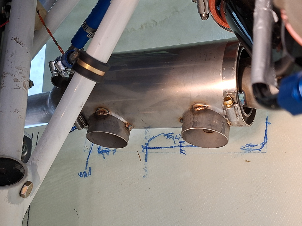
Made a test fit on the airplane and temporarily fastened the nuts with a lock washer on the cylinder studs. I should not have used the lock washer as you can only use these once and as I mentioned earlier, my engine will need to come off again when it goes on the test bench. I learned this later on so I'll have to buy a bag of new ones with my next spruce order. The nuts used here are 5/16” and the Superior overhaul and install manual tell you in appendix C that 5/16" (Nut & Cap Screws) are torqued to 200 inch/lbs.
Then put together the pilot side exhaust and did the same. Don't forget the gaskets between the pipes and the cylinder head. These can be reused so no issue to put these on.
More nickle based anti seize and install it.
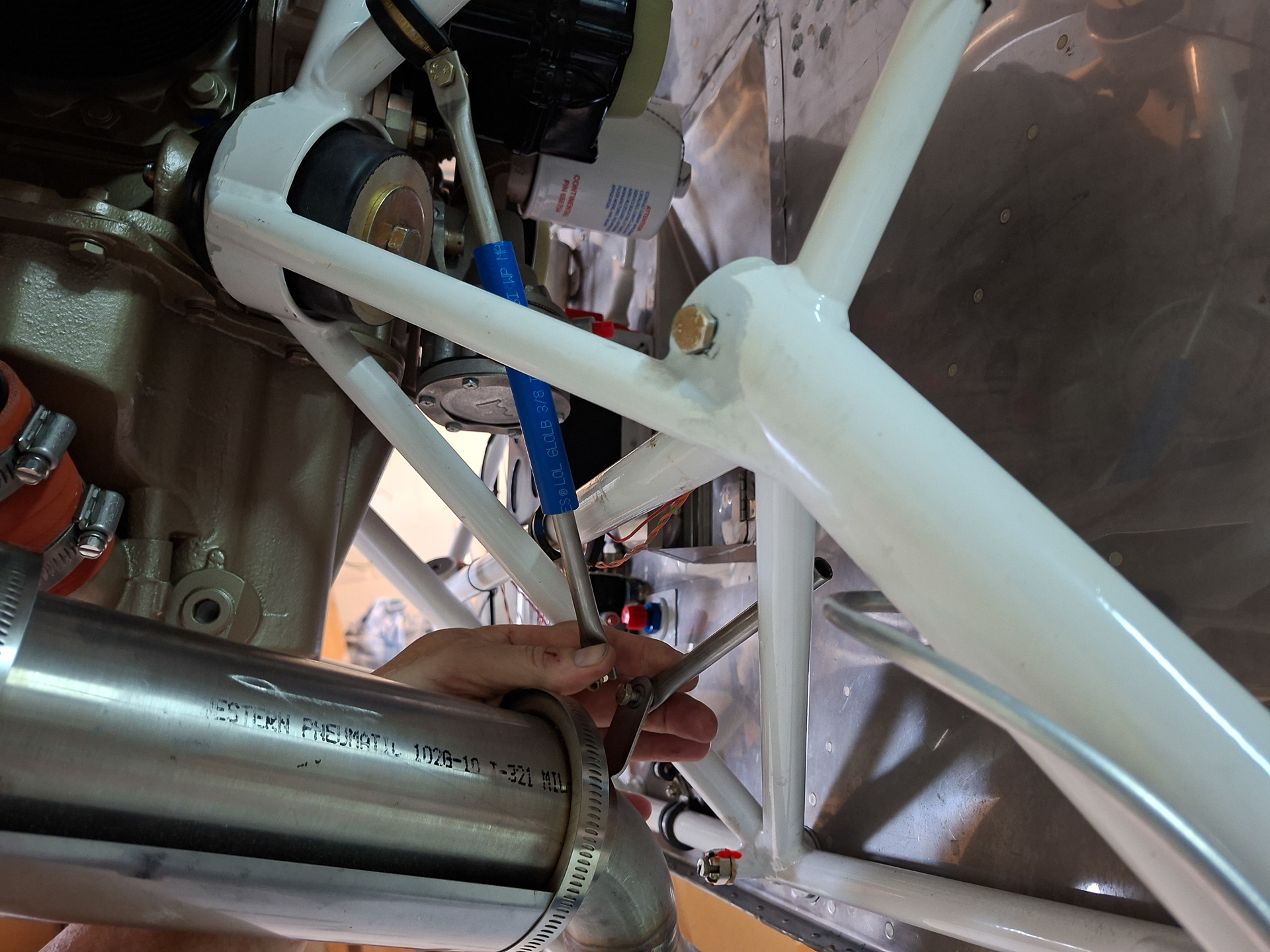
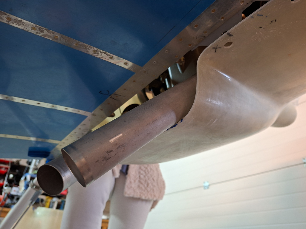
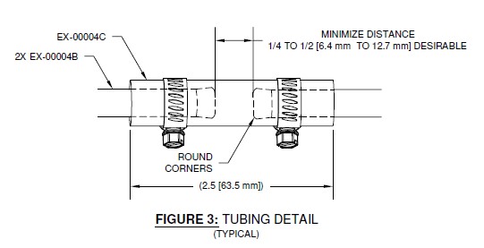
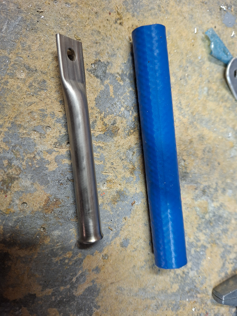
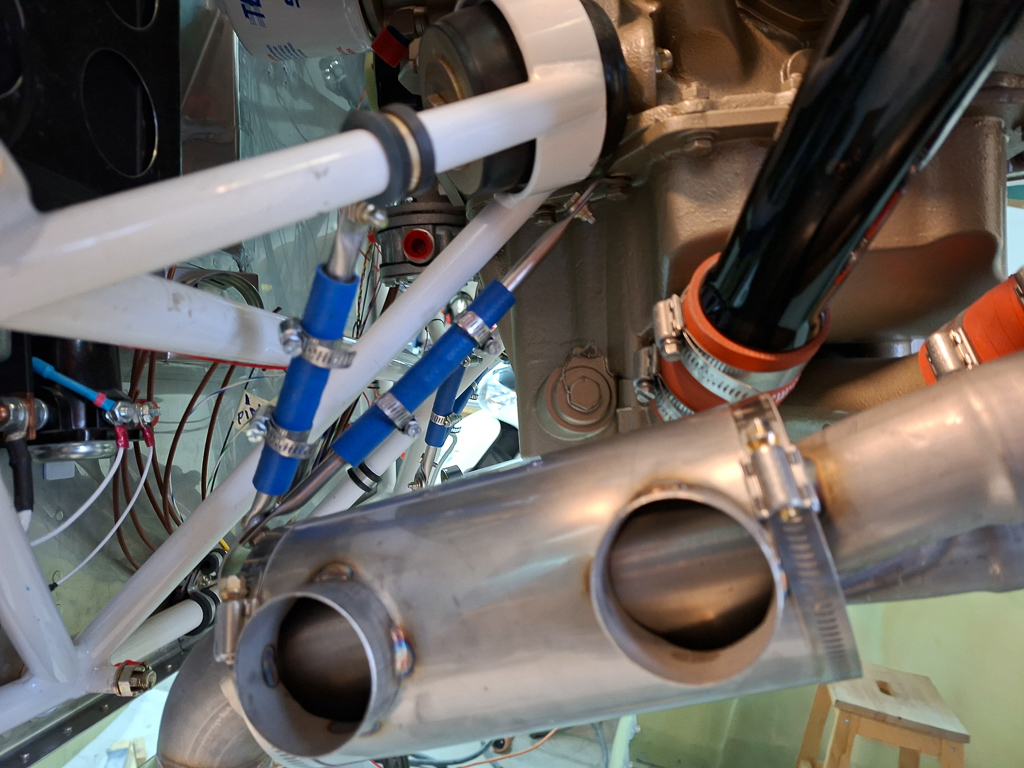
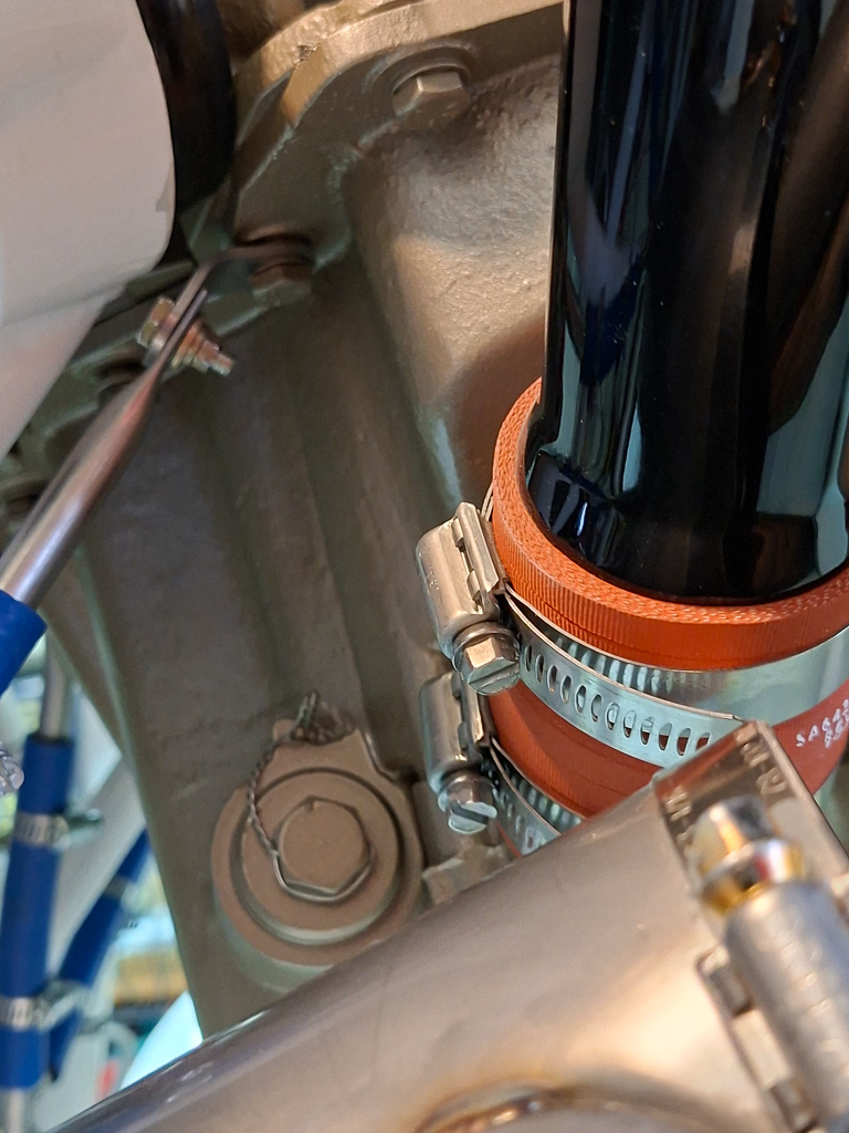
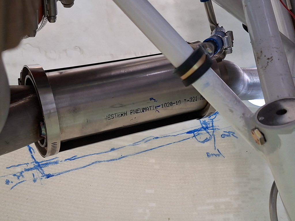
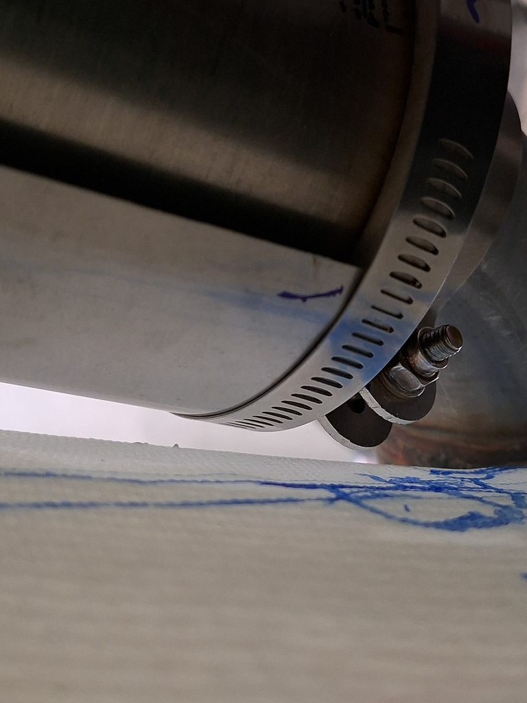
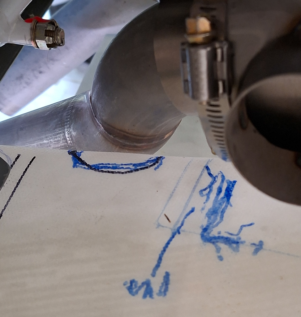
So far things were easy... now for the real problem... I have literally no idea yet on how I'm going to hang the exhaust pipes. Vetterman has supplied 2 clamps and some support parts that go together with a rubber connection piece (the blue part in the image). The drawing that came with the exhaust is not applicable for me. The muffler is in the way.
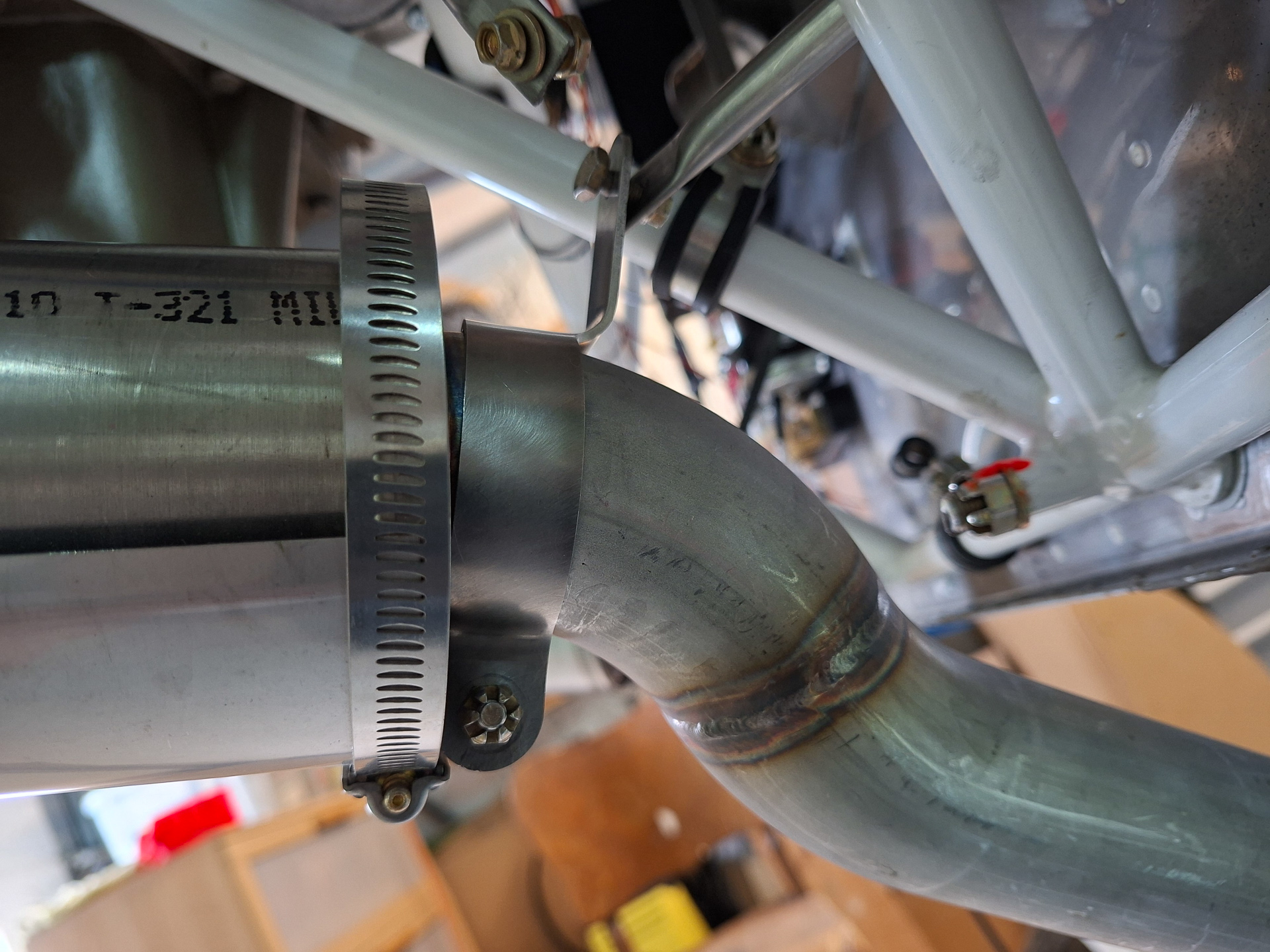
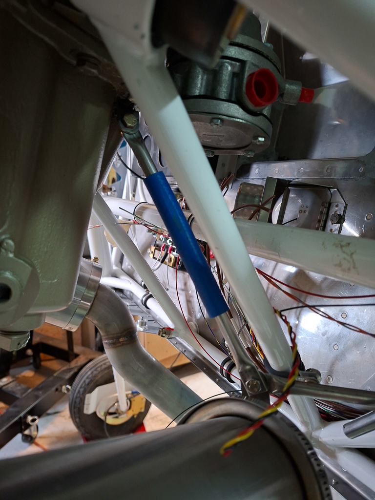
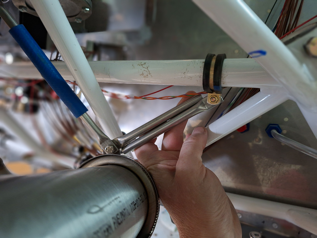
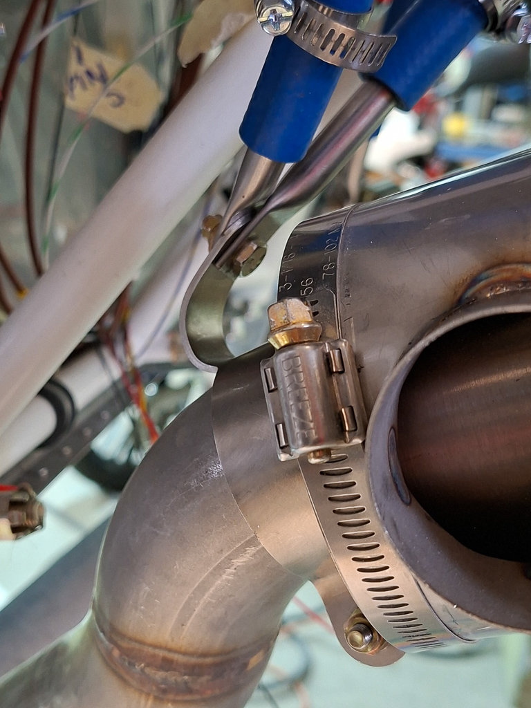
I can either install the clamp next to the muffler or move the clamp lower on the exhaust pipe. The position near the muffler is not ideal. As you can see in the image below, the clamp is too wide to fit nicely over the pipe and I'm afraid it will nick the bend of the pipe. On the other side it also interferes with the weldings from the muffler on the pipe.
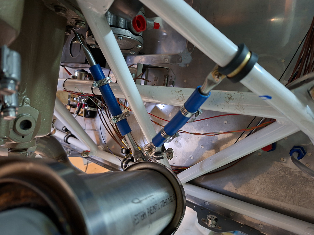
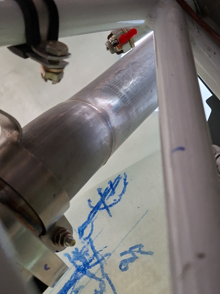
The other option is to move the clamp down as in the image below. The distance do the cold air sump is too long so I probably won't be able to hange the exhaust pipes to the engine. Another option is to hang them from the engine mount. That's not ideal as the engine vibrates and the engine mount is static.
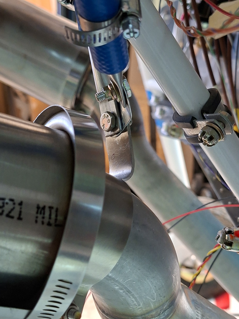
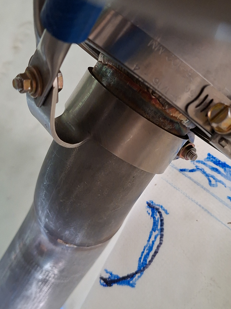
Here is another variation of hanging from the top position.
At this point, i'm going to let this rest for a while and try to do more lookup work in how others have also done this. I have seen an image on the Vetterman site where he hangs the pipes using an angular support from the bottom engine mount tube. I have also seen a builder hanging the exhaust of a piece of rubber (as used for sealing the cowl) from the bottom of the firewall. We will see how this turns out at a later stage.
30/07/25 - Starter fitting - 1h
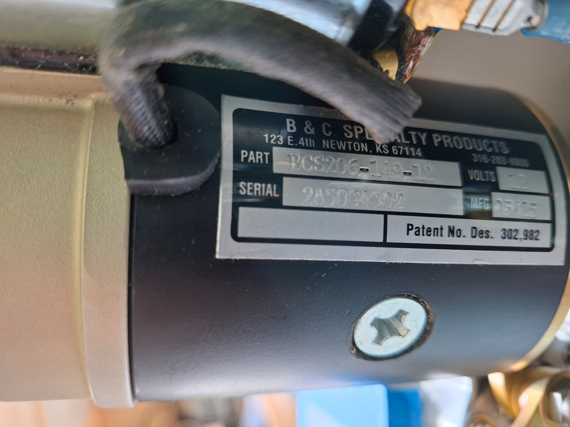
My starter motor is a B&C specialty products BCS206 experimental starter. The full name plate is shown below.
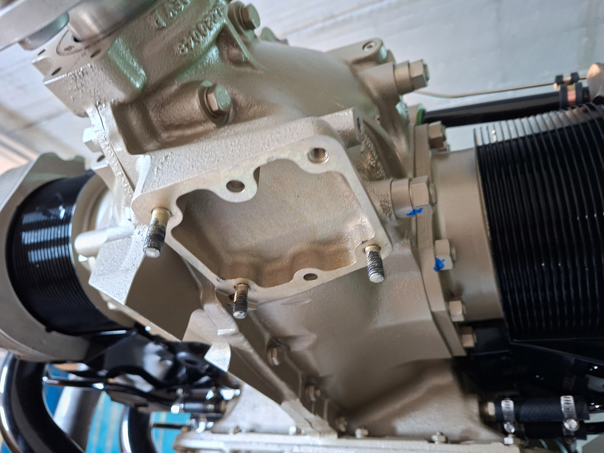
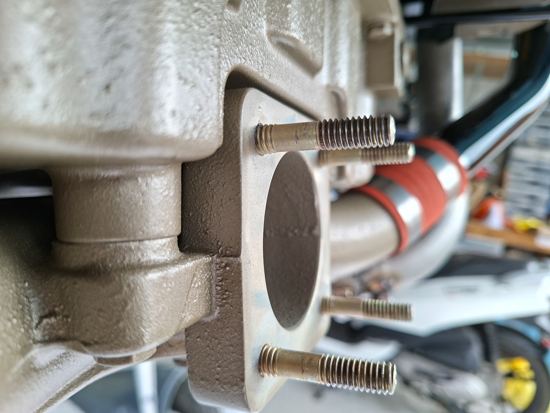
It mounts at the front right side. There are 3 studs in the engine case, the 4th one is a bolt. I put some anti seize on the studs and test fitted the starter on the studs.
This sounded easier than it would be in reality... The starter is too long and interferes with the fuel throttle body. With the spacer in place on the fuel throttle body, the starter can't go on. So first I had to remove the fuel throttle body and take out the spacer so the throttle body would move backwards. With that done, the starter could be put on the studs.
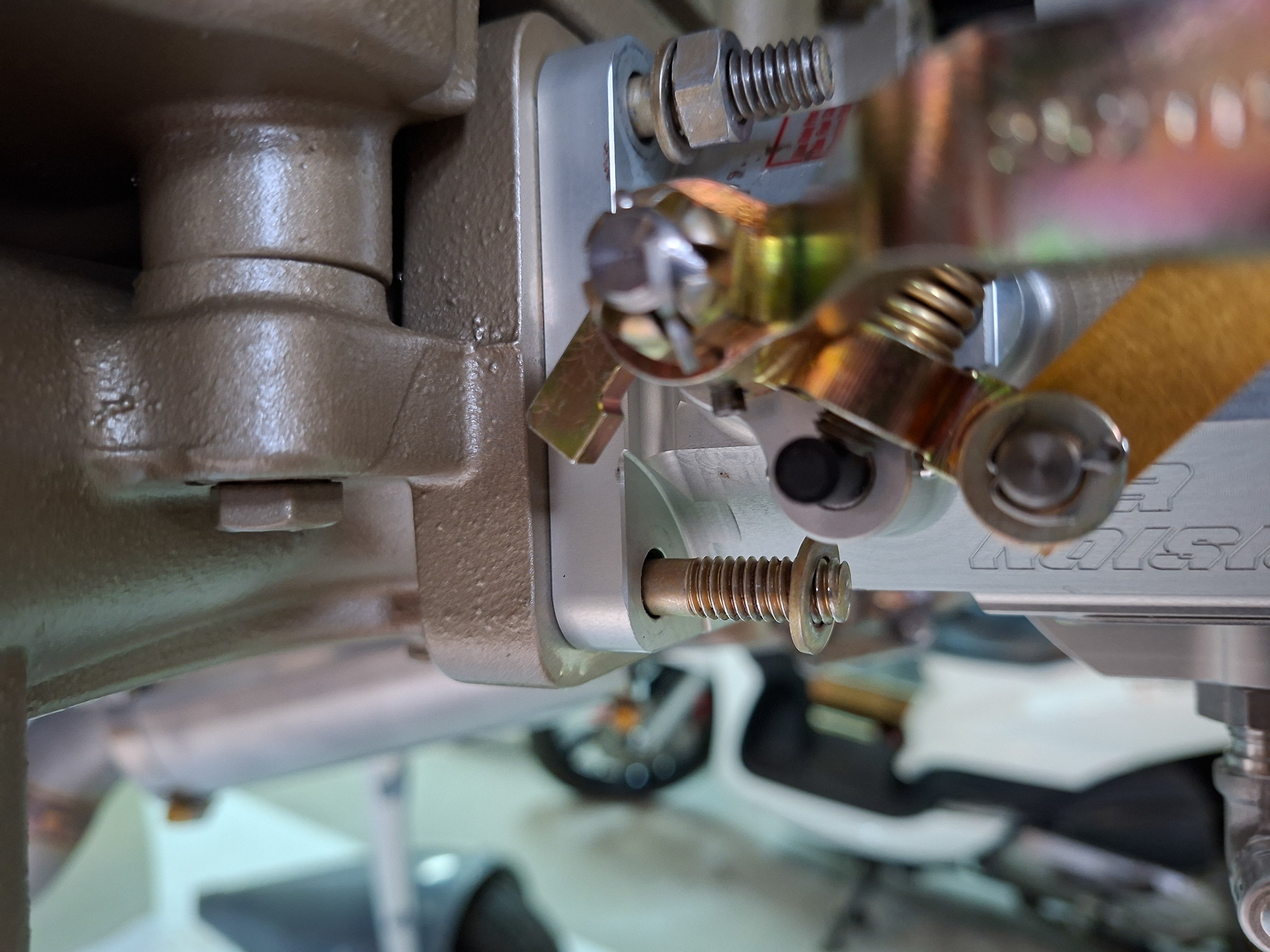
This gives me the next problem. The studs on the throttle body are placed in to count for the spacer. As you see image below, there is no thread on the stud if the body moves closer to the engine case. I either have to use a lot of washers here (4) or try to screw the studs more into the case. Werner who build an RV8 and had the same engine told me he was able to invert the studs in the case and that this solved the problem for him. I tried locking the stud with 2 nuts and tried to get them loose but no way they were moving. I'm afraid of breaking them and having an even bigger problem so I'll consult with PMM (my engine supplier) to see what I can do here as I don't like the 4 washer idea either.
As you can see, the spacing is really really tight here. The lever in the picture is the mixture control. You can adjust the orientation of this lever so this will normally not be an issue.
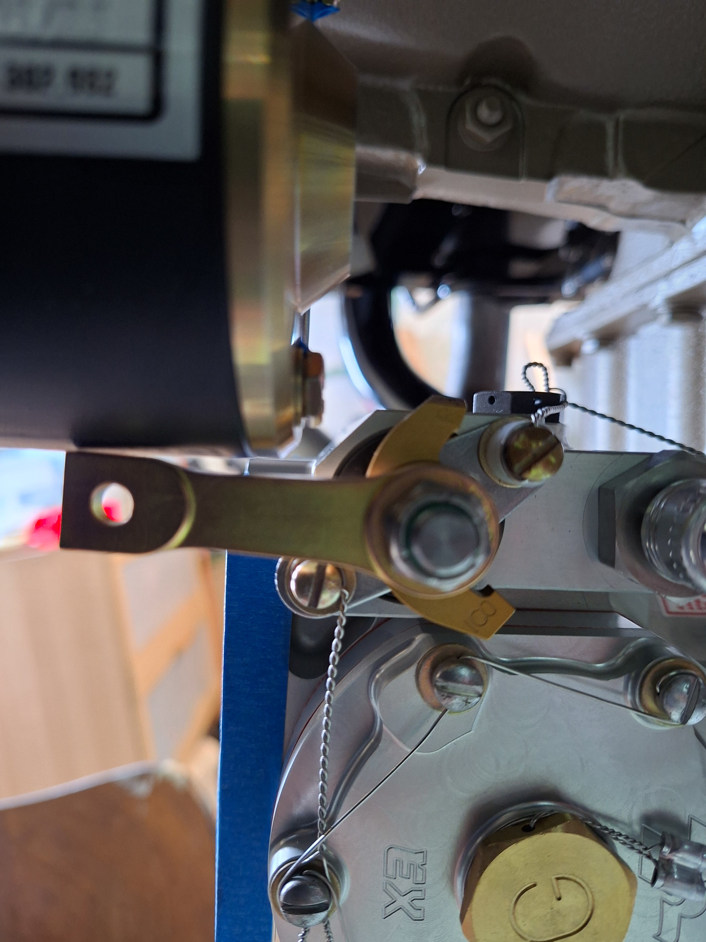
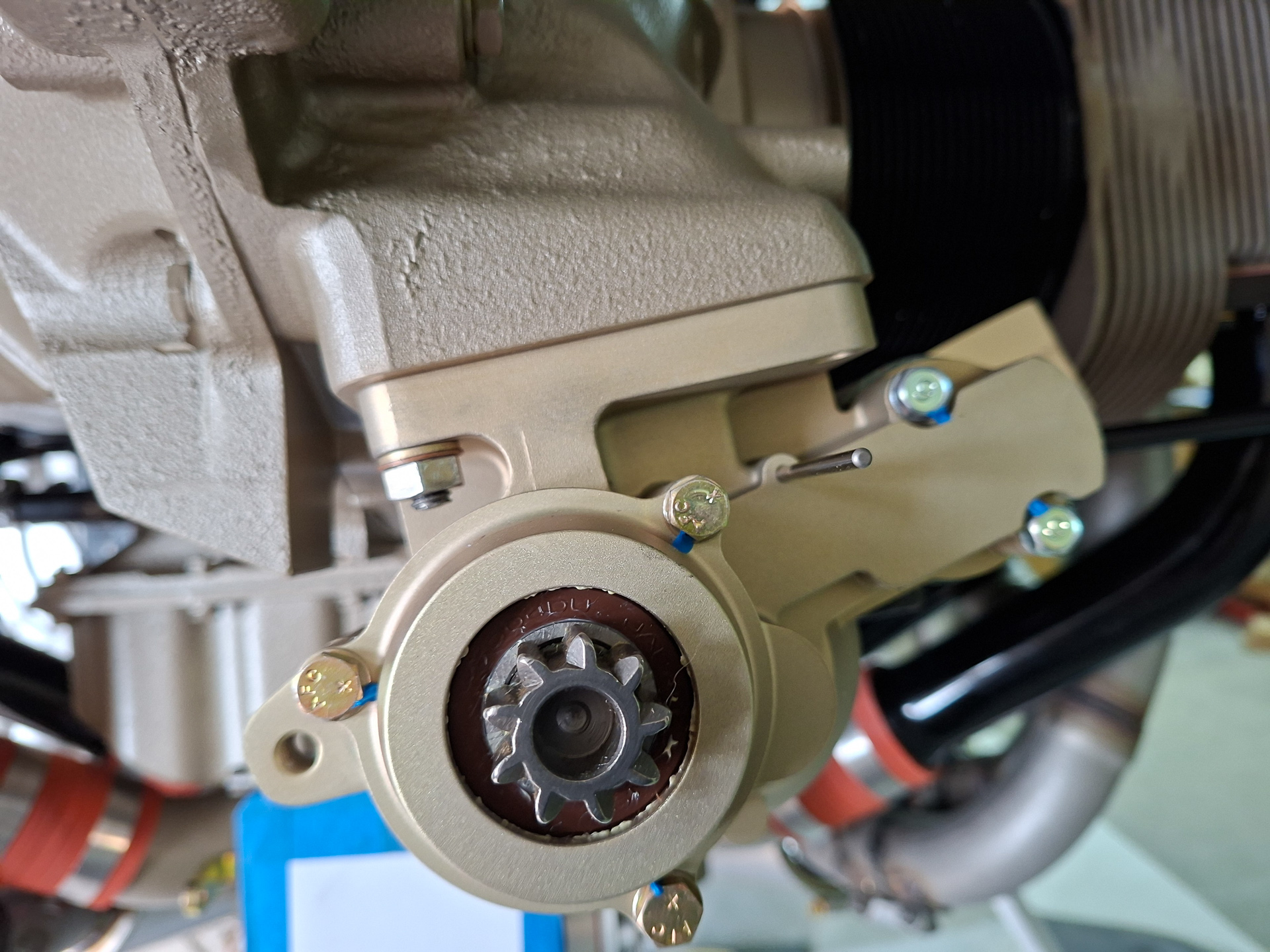
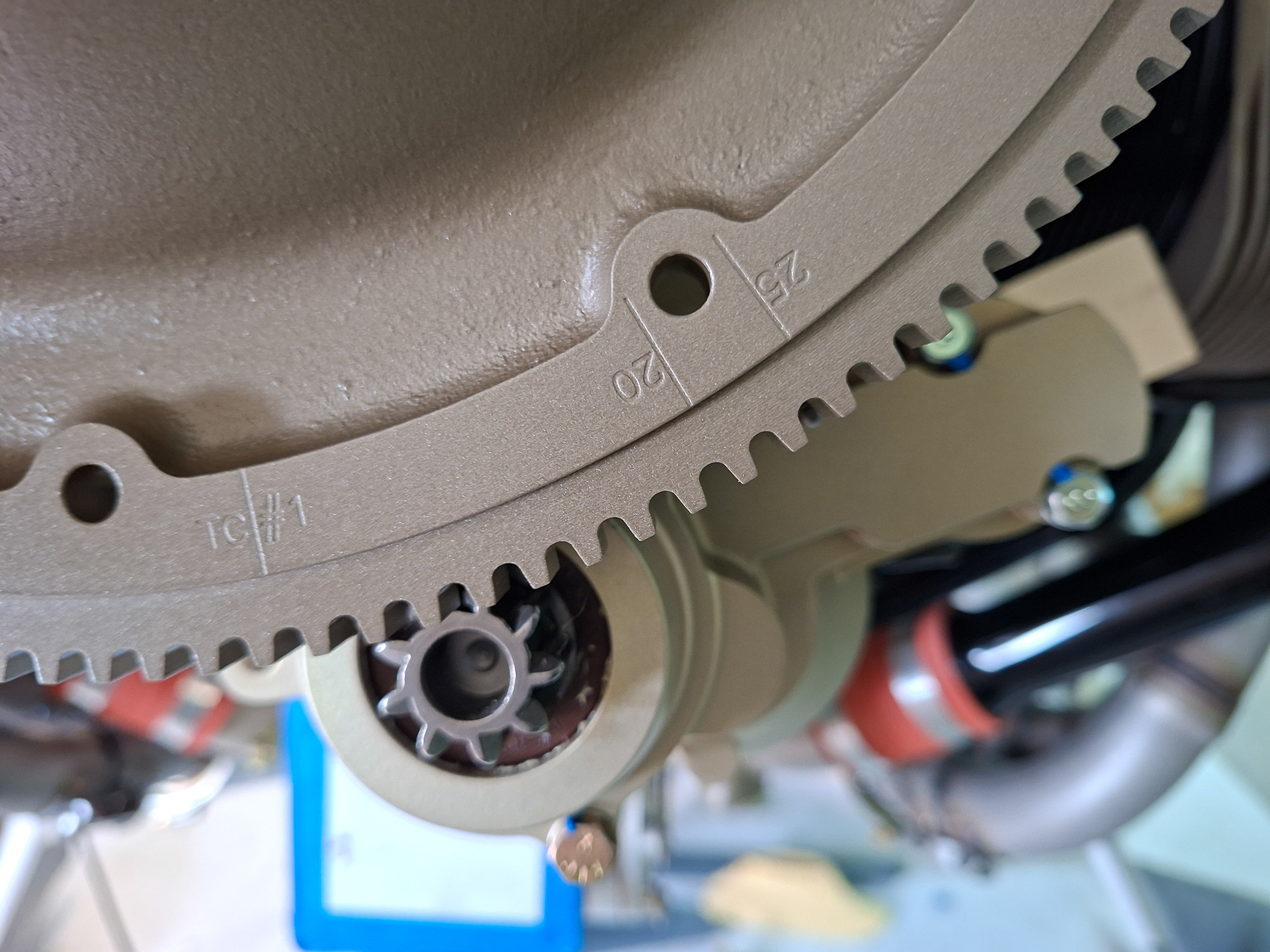
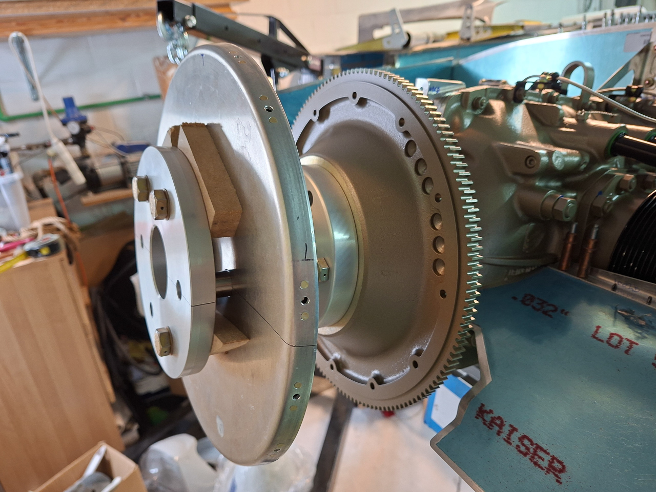
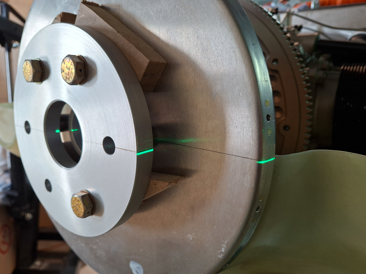
The starter motor is delivered with a pin. This pin is installed in this picture in a dedicated hole. The pin is used to align the cylinder position on the starter ring.
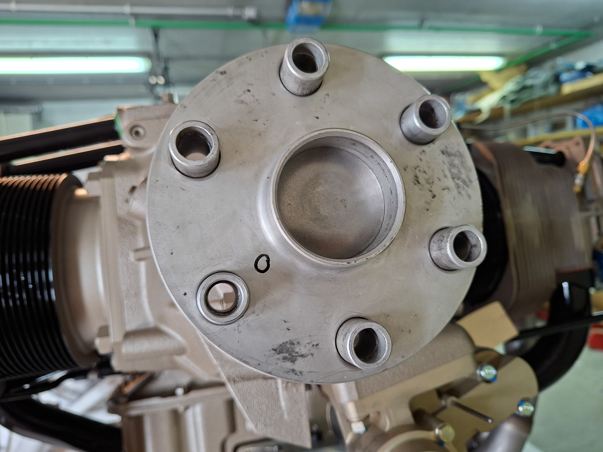
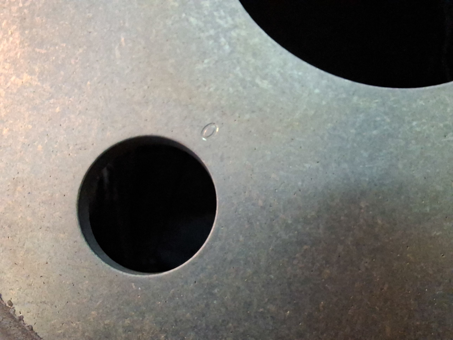
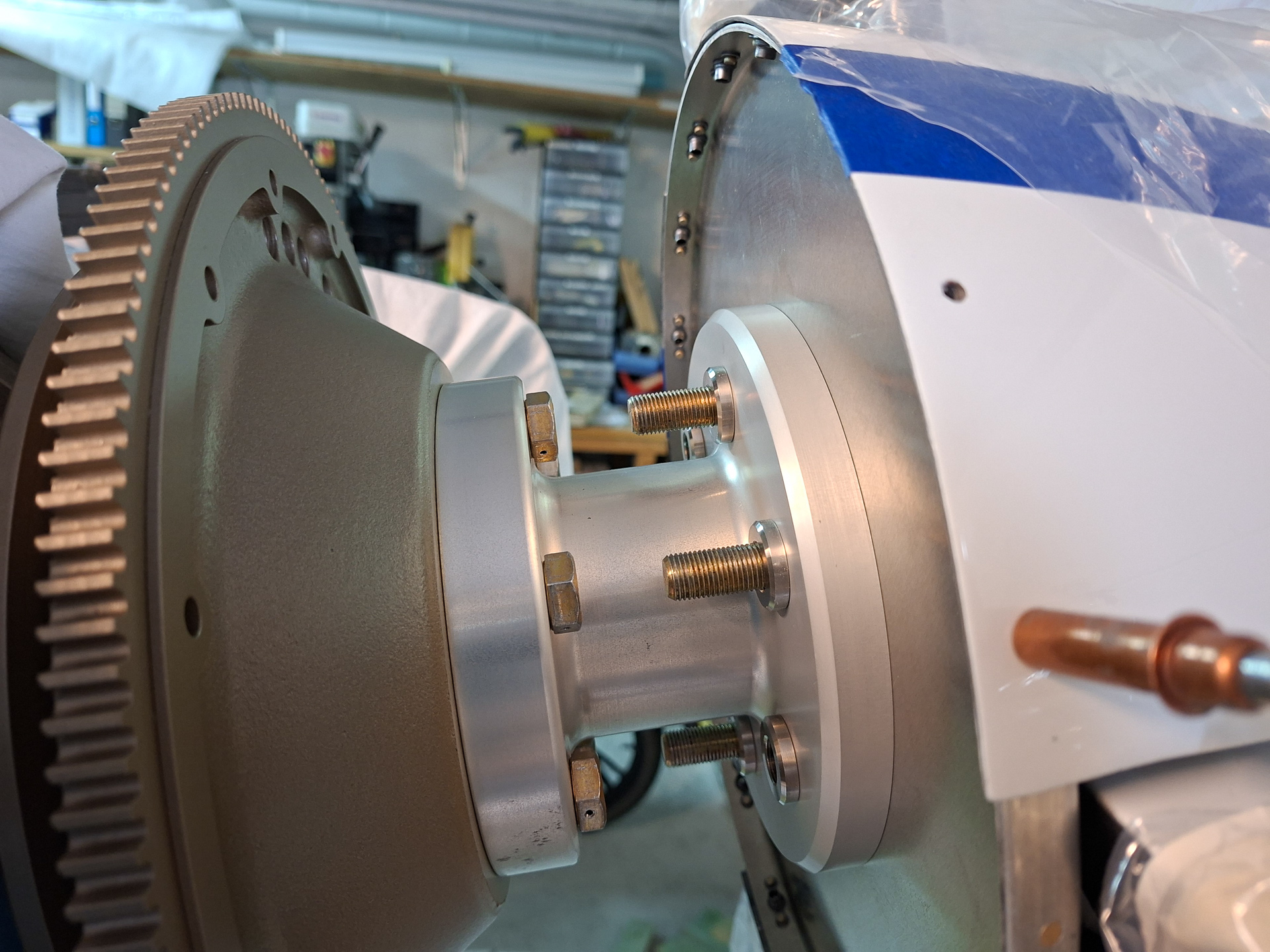
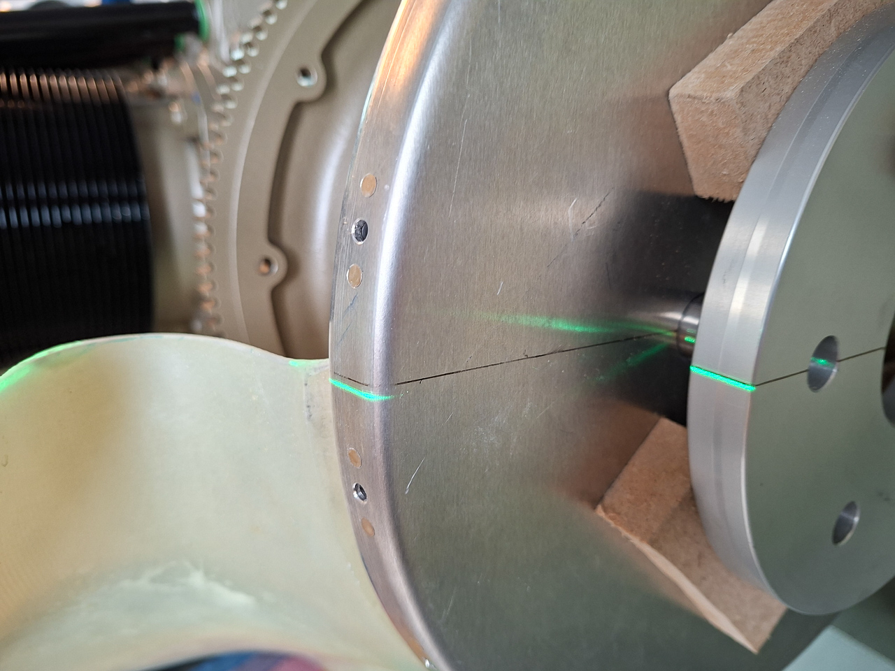
My prop hub has a marking "O" on one of the studs, made by PMM.
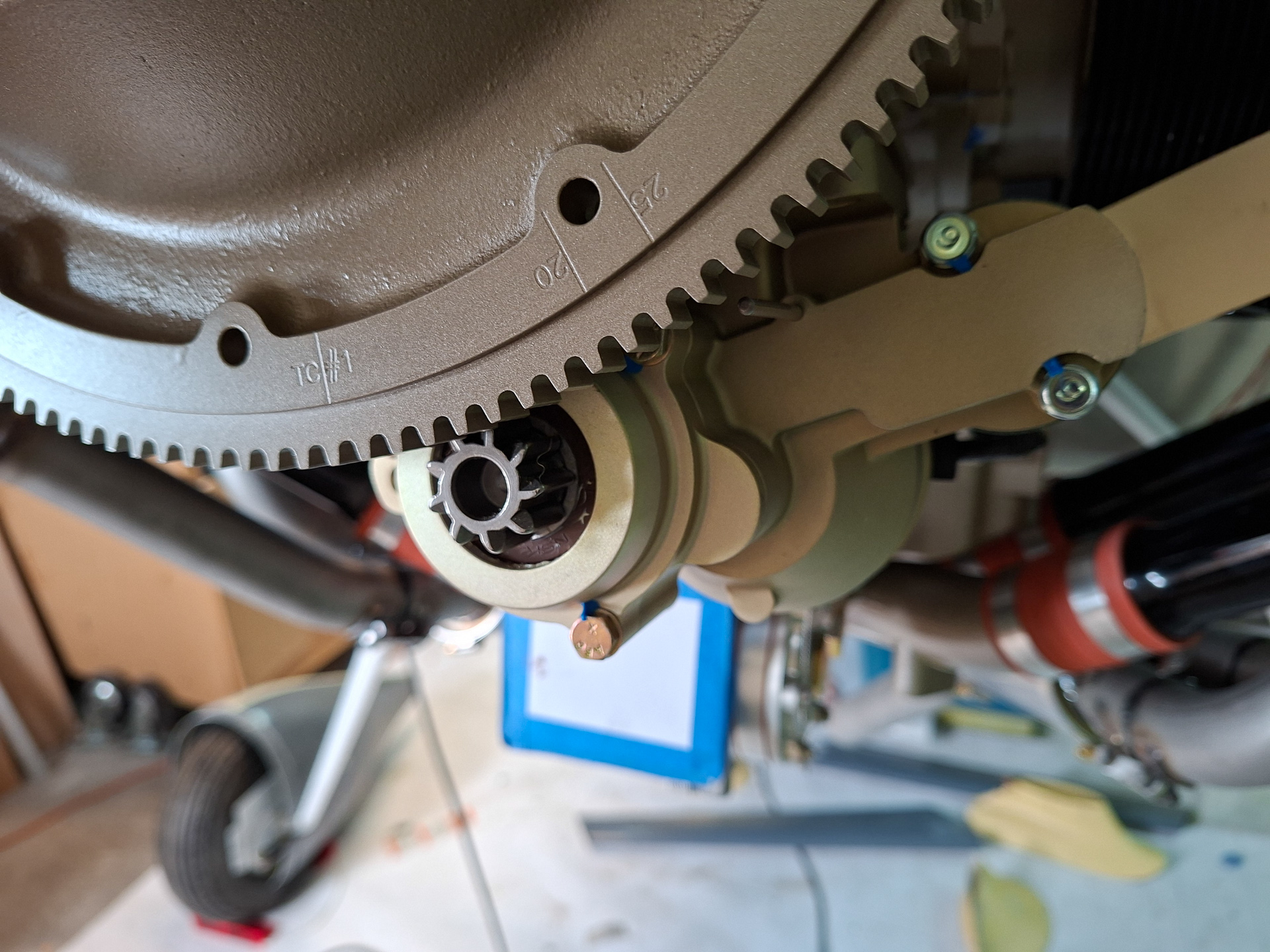
The starter flywheel ring itself also has a marking in it showing a "O"
These marks the right position of my flywheel on the prop hub. When installed, you can see that the pin points to a position on the ring.
Difficult to see in this picture but the pin points to the 25 degrees spot on the flywheel.
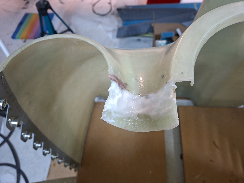
30/07/25 - Starting Baffles - 3h30
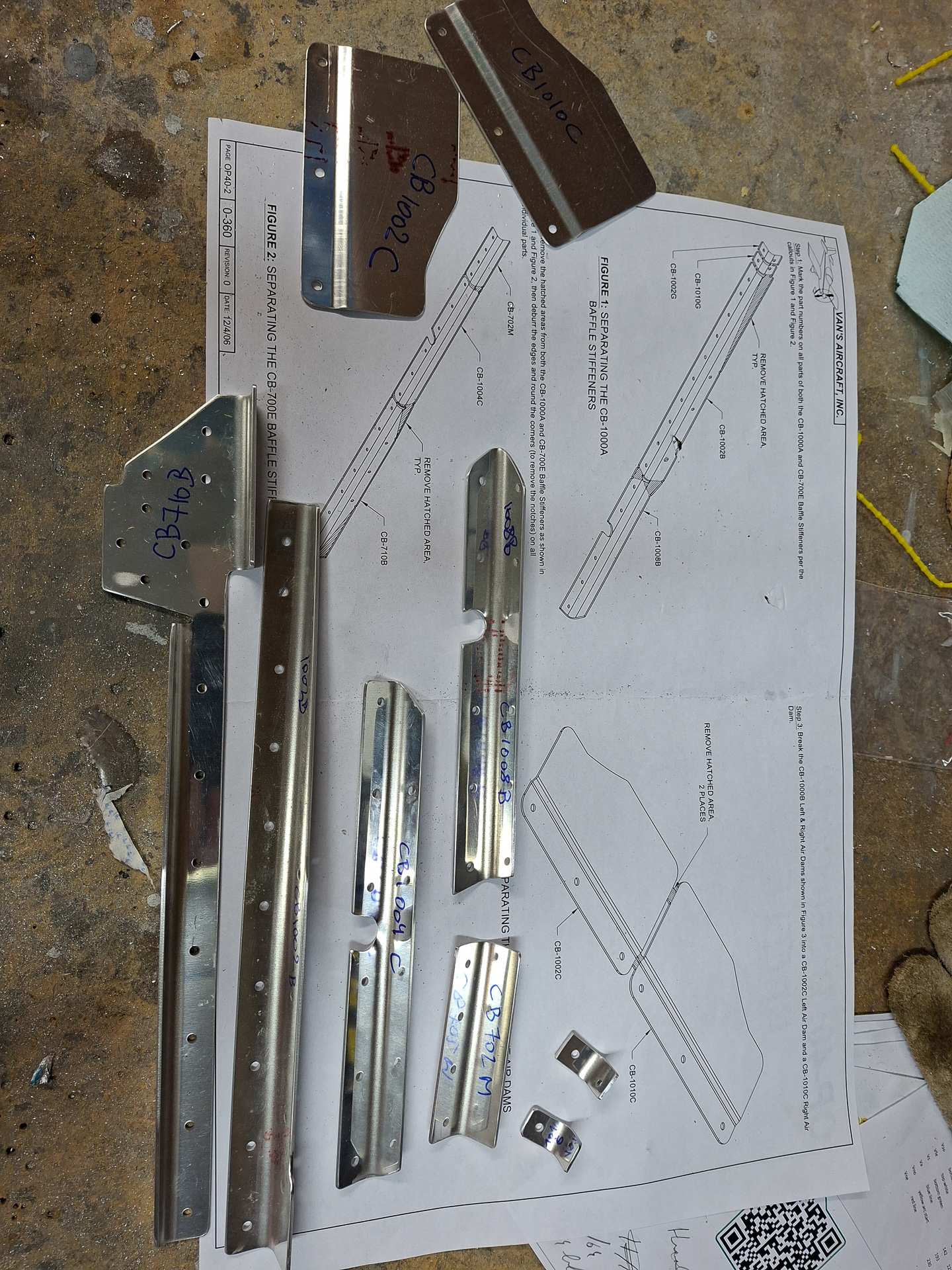
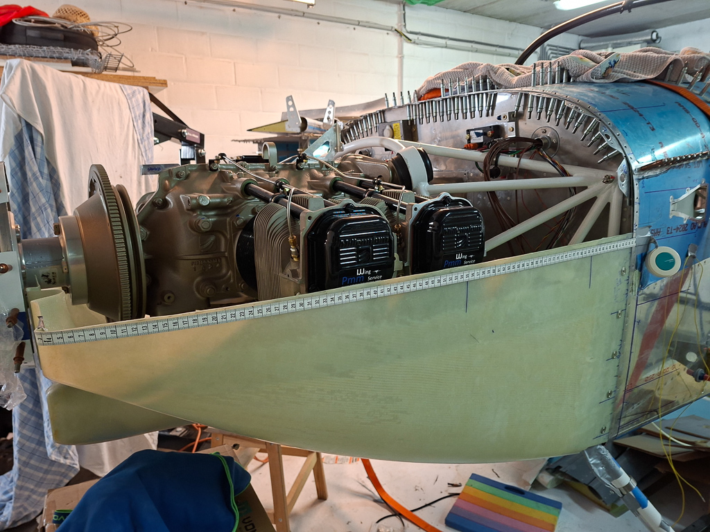
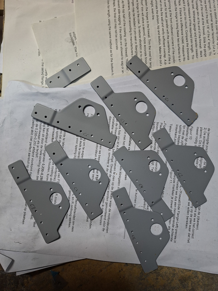
Starting engine baffling. I purchased the Vans Aircraft IO360 baffle kit. The Sam James manual also gives cut out plans for baffles but it's much more convenient I think to use the Vans kit and adapt it. I cannot fully install it as is because I'm using the Sam James plenum. This plenum lays much lower on the engine and creates a high pressure air chamber above the engine. The Vans baffle kit is using flexible rubber sealing against the top cowling. The plenum does not require this and is a much nicer solution but it means that the top of the baffle kit will have to be shortened quite a bit in order to fit nicely with the plenum. I couldn't think of anything other to start with for now so I'll take this as far as I can for now by following the baffle kit plans until I hit the forward side of the kit where the differences become too large.
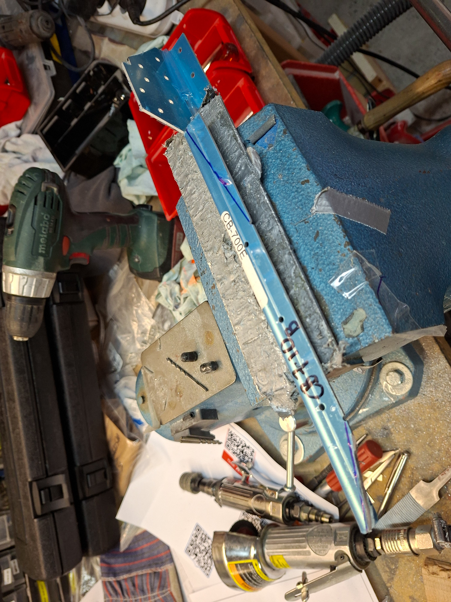
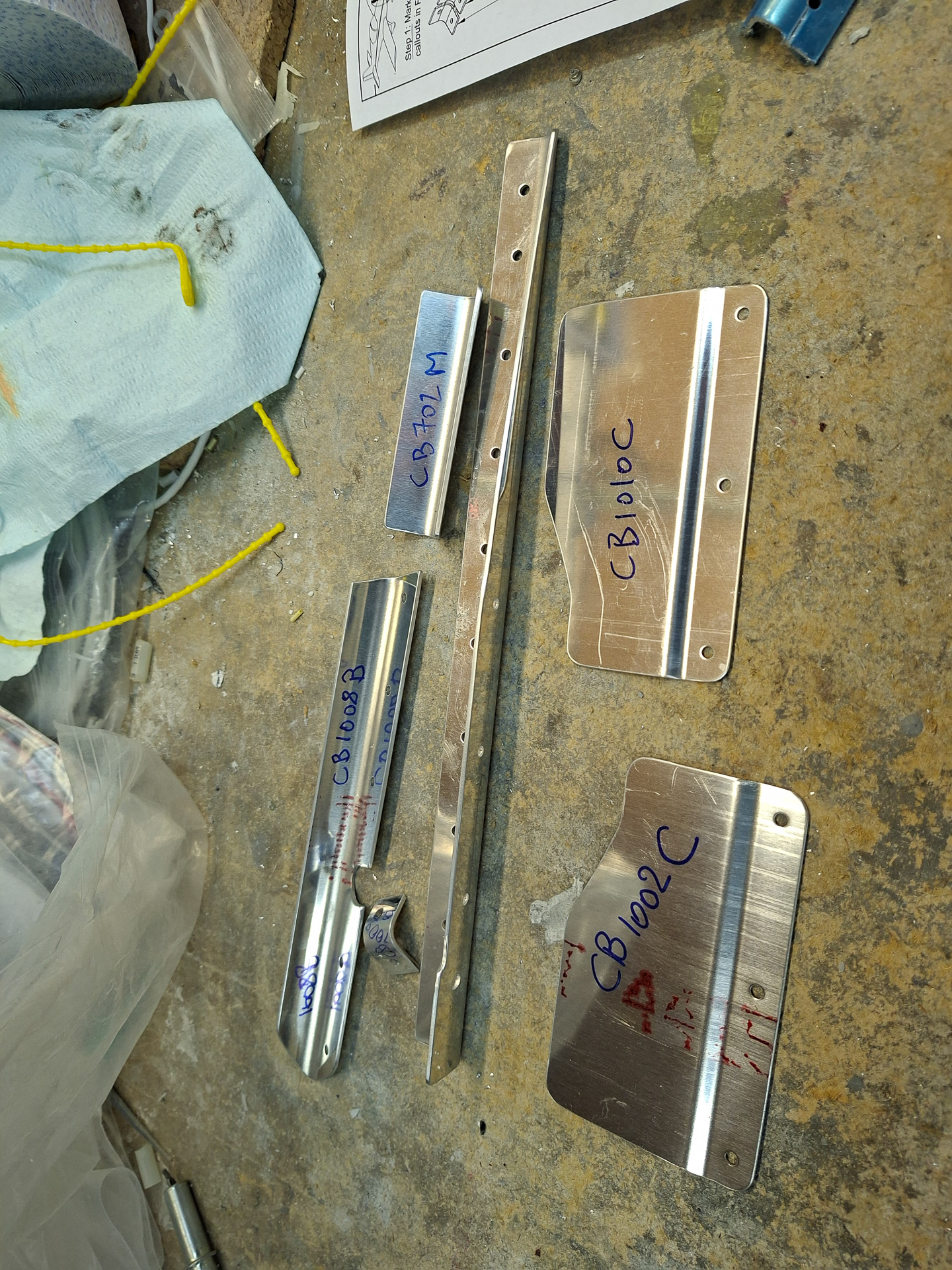
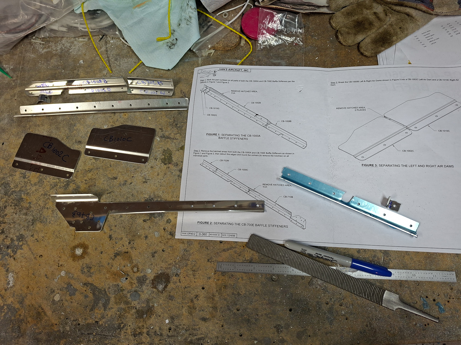
Started by making cleaning and deburing a lot of the small parts described in the first parts of the manual.
I forgot how much time it takes to clean edges, 3M polish edges and sand the parts.
In the end of the session I got at least some of them ready. At least I'll know what to do in the next days. There are plenty of pieces.
31/07/25 - Baffles continued (part 2) - 8h
Day 2 of working on the baffle kit. Continued today with deburring and cleaning up of the small pieces as described in the beginning of the plans.
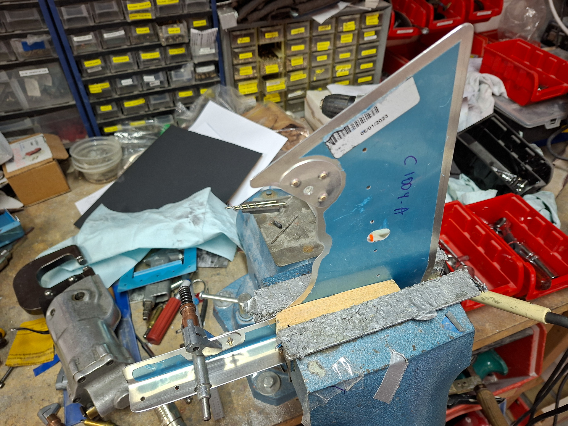
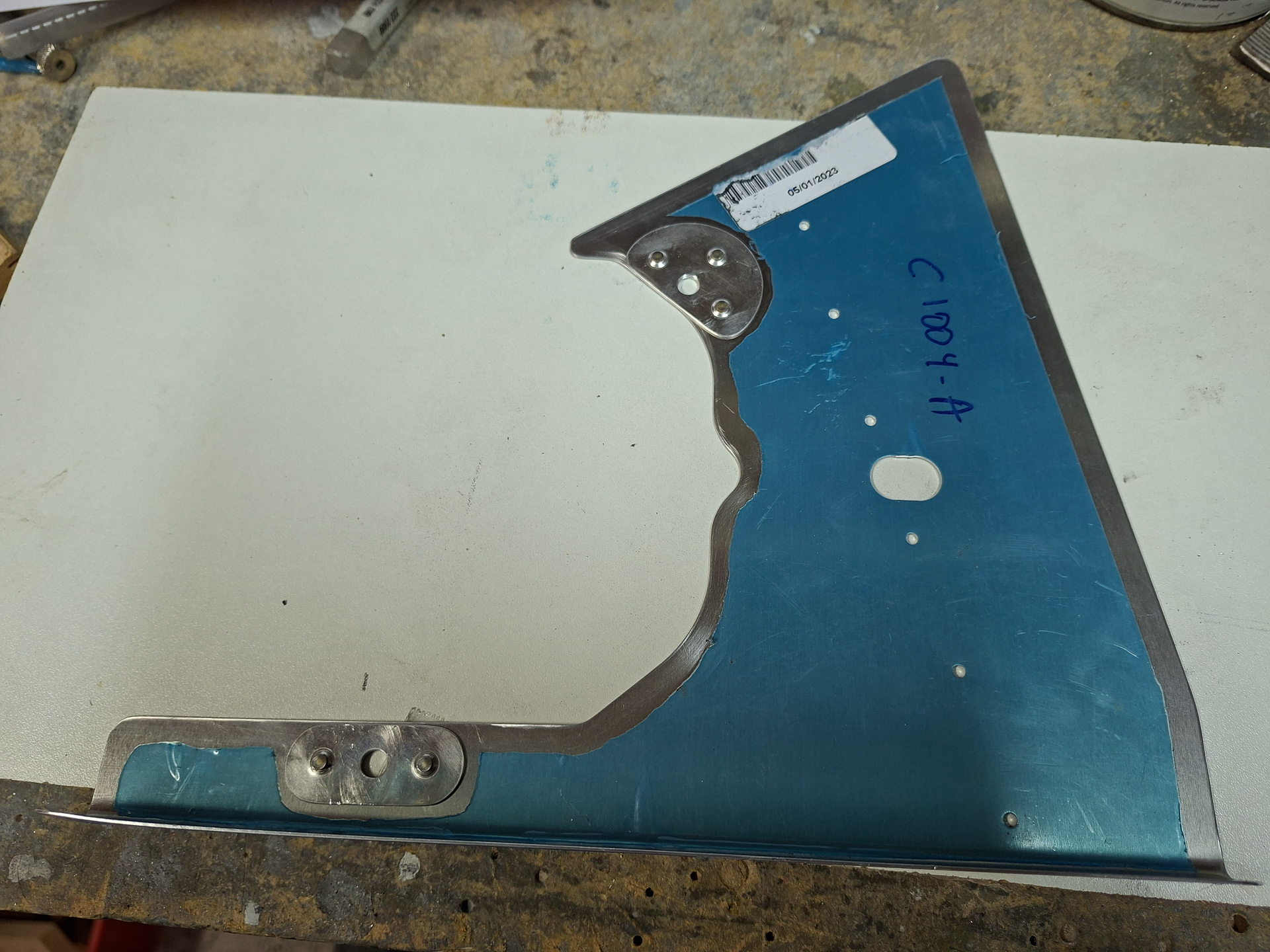
Next, worked on the pilot side rear side panel. These are very funky shapes and it takes a lot of work to get them in place. The picture below shows the CB-1004A piece that sits over the cylinder head (rear-left). The shape of the cylinder cover is cut out by Vans but it's an initial guideline and has to be further adapted to fit your engine. The rubber gasket between the cylinder cover and the cylinder body is also not taken into account for so you may need to cut out more to give room. You also don't want to cut too much as the fit between the baffle and the cylinder head needs to be tight so no air escapes. The whole deal of baffles is to create a high pressure chamber on top of the engine and every leak you have here will reduce the cooling capabilities for the engine.
2 doublers are installed which reinforce the area where the screws are holding the baffle to the cylinder. The cylinder head had predrilled tapped holes that align perfectly with these holes in the baffle.
Next also deburred the rear left baffle. This is where the oil cooler will be mounted. The plans have you work on this and cut out pieces now but as I'm using the Sam James plenum, I can't really do that now. I need to know the exact height of the plenum before I can do any cutting. At this point, I started to realize that in order to know the position of the plenum, I need to have the exact position of the inlet holes of the Sam James cowling. Which means, I need to work on positioning the cowling real soon as all the rest is defined by that. In order to install the cowl, I'm wondering if I have to rivet my top forward fuselage skin... I really don't want to do that as there is some electrical wiring work left for P-leads, sensors, organizing wiring,... too much to think about...
Moved on to the next part of the plans, working on the passenger side rear and rear side baffles. The circular shaped metal in the top are the fins that will be place underneath the cylinder and which guide the cooling air. They are annoying as you have to be careful while you are temporary fitting this that you don't ruin the paint on the cylinders
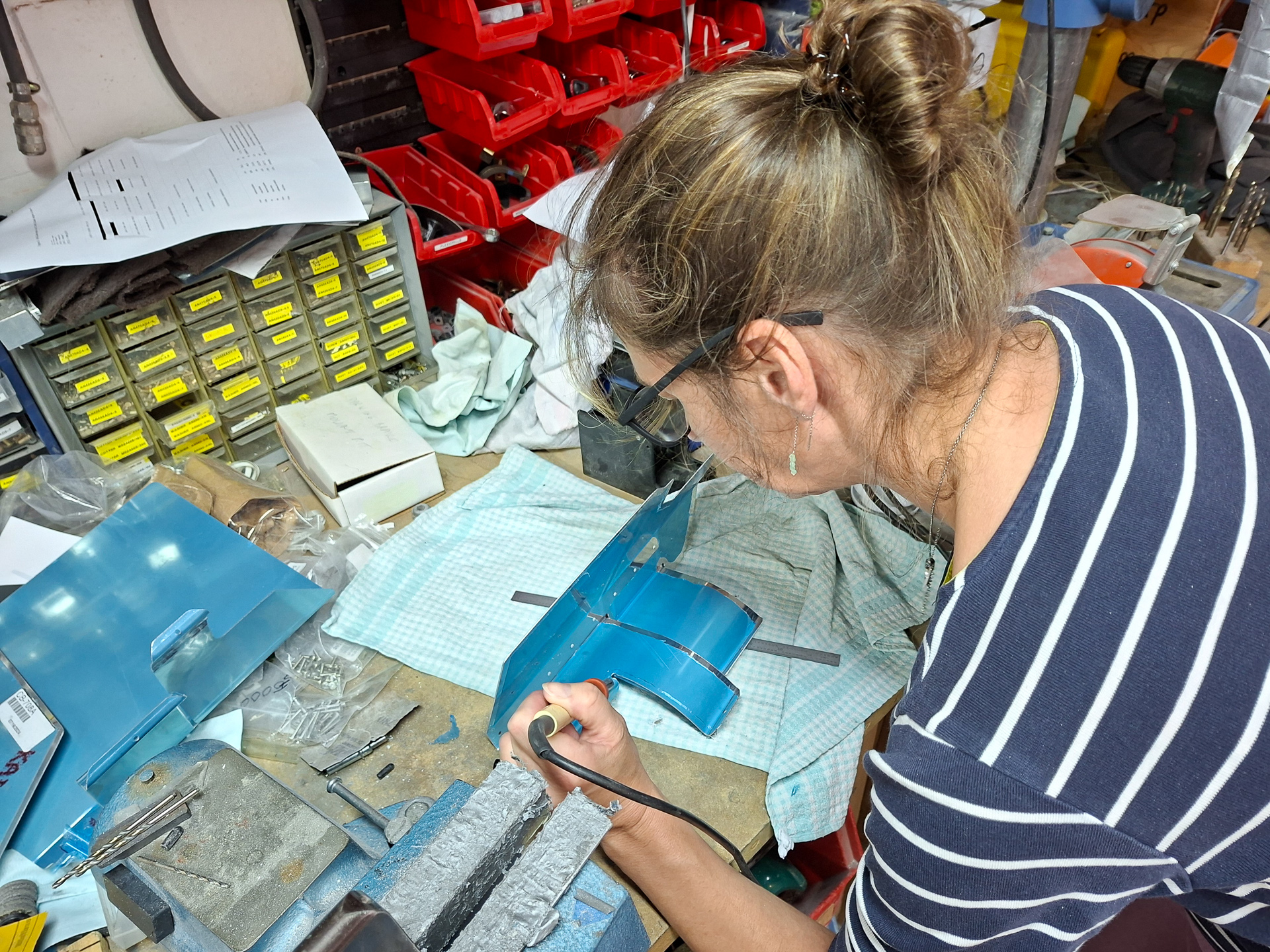
As I have been doing since the start of the project, I try to leave the blue protective cover on the aluminum as long as possible. This does give you some extra work with a soldering iron to free the edges that you will deburr. Fortunatly my wife Cindy gave me a hand here and saved me a lot of time.
2 more parts done and doublers rivetted on.
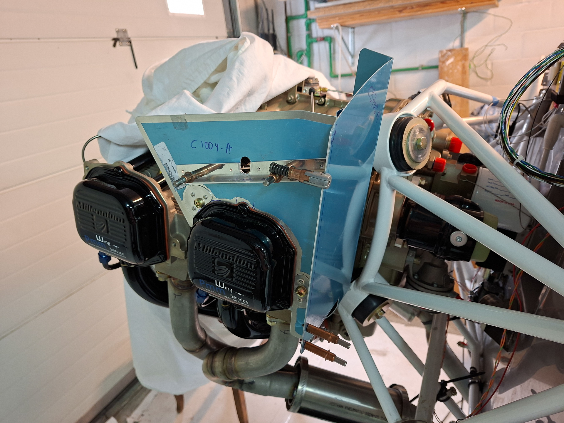
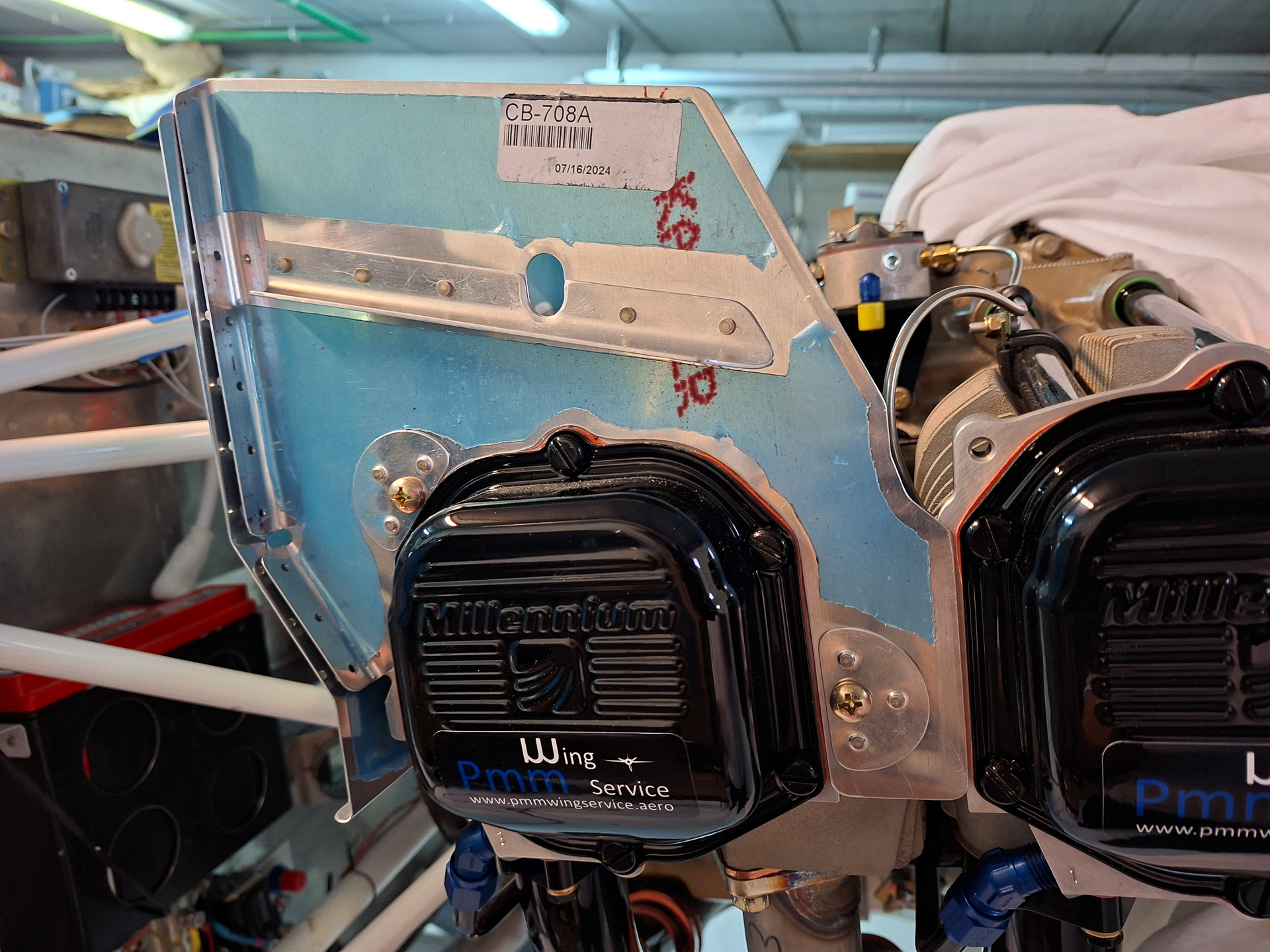
Installed it on the engine. Some people have reported a gap needing a shim between the two parts but as I rivetted them together, they looked pretty close and I couldn't see the need for any shimming here..
Top view of the same parts.
I needed to remove some extra material on right bottom side as the baffle was interfering with the engine case.
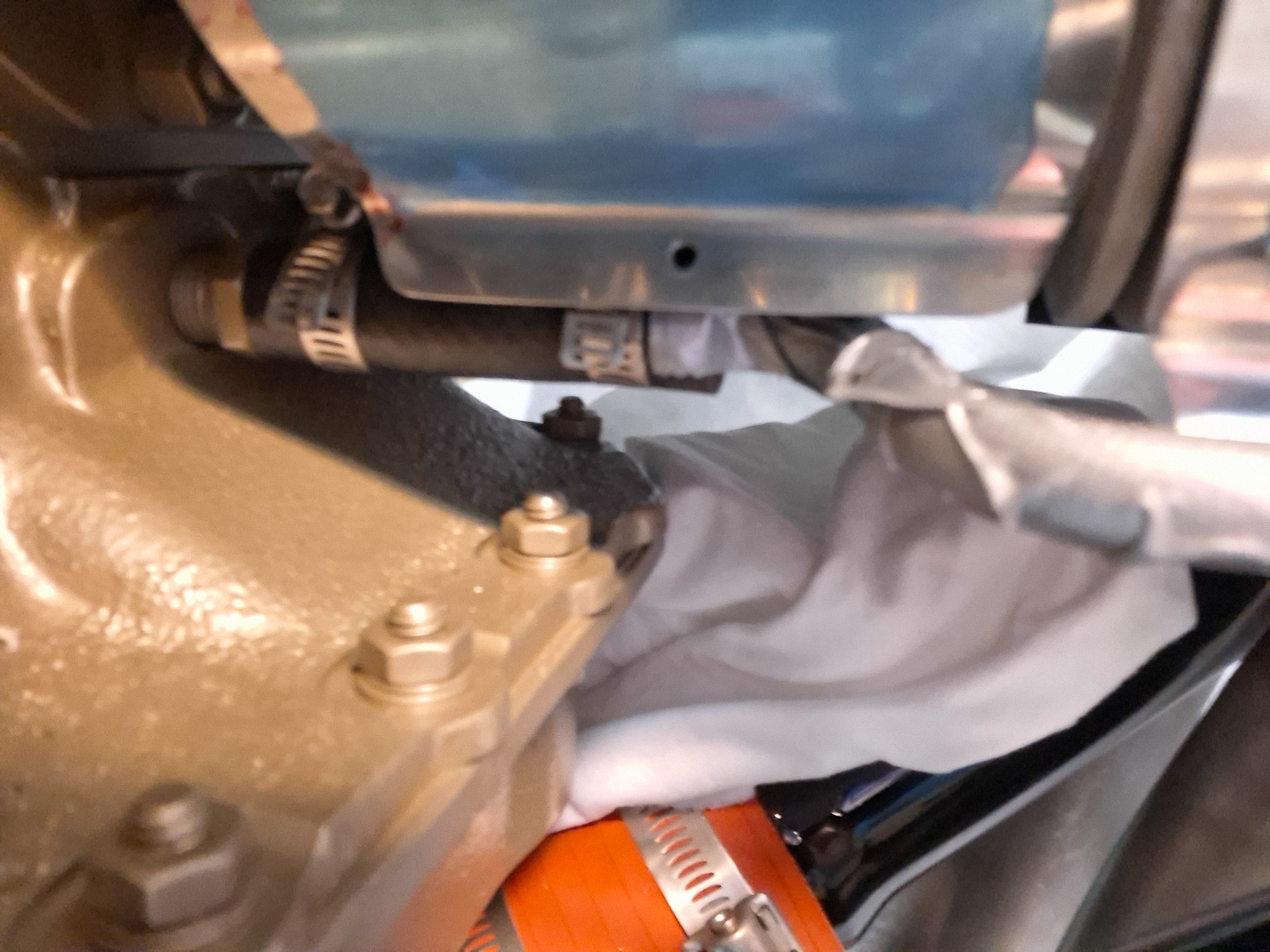
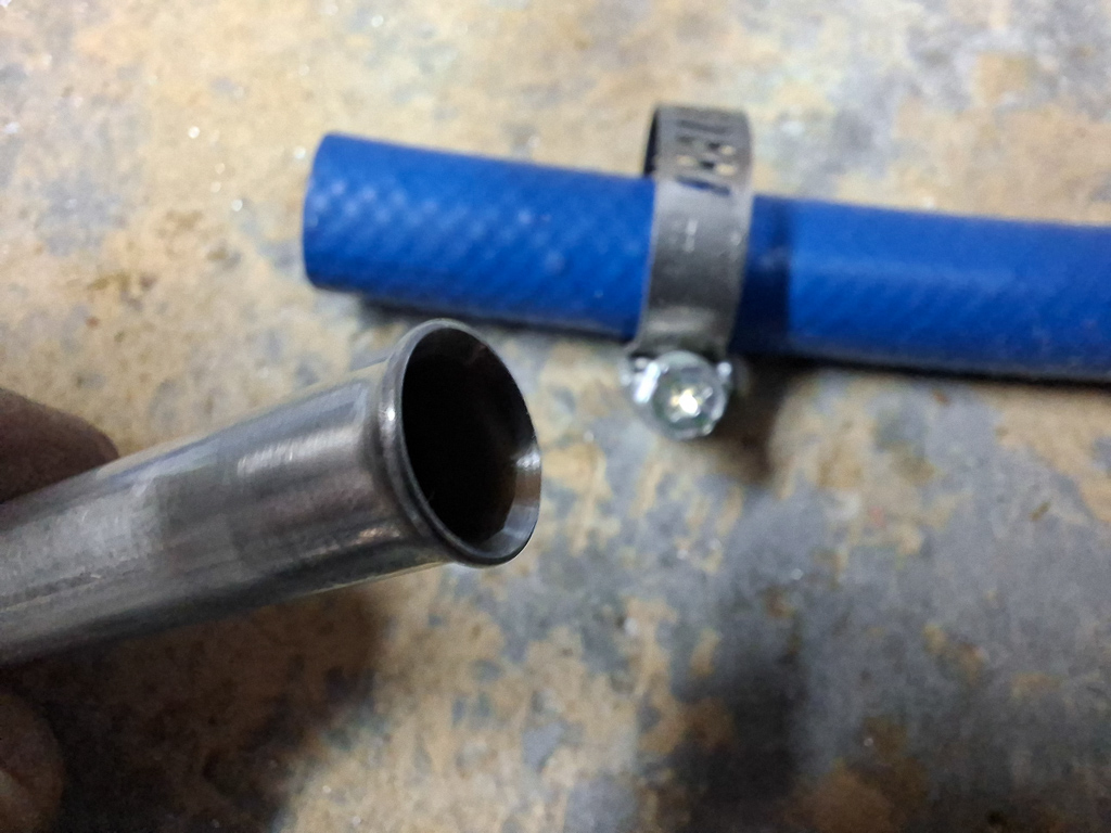
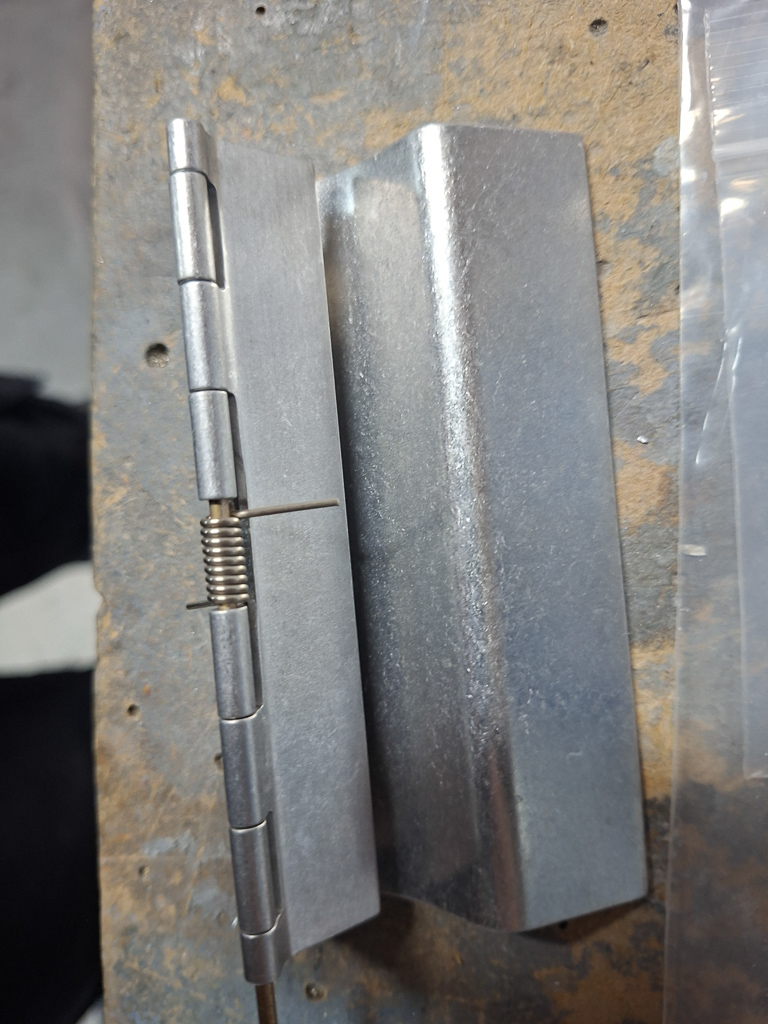
I had a lot of issues getting the circular bottom cylinder cover over the cylinder and trying to get the part on and off. Finally, after a couple of iterations I realised the hardware steel clamp over the black rubber hose was preventing the baffle to move over it. I could simply fix this by loosening the hardware clamp and reorienting the locking part by rotating it 180° towards the bottom. Now the baffle can slide nicely over the rubber. In the image below you see the problem before it was solved. the clamp had the same position as the one you see on the left where you can also see the locking part sitting high over the rubber hose.
01/08/25 - Baffles continued (part 3) - 9h
Day 3 on the baffle project. Work continues on the front side walls of the baffle cage. Most of the work and time is lost in deburring and cleaning the parts. The interesting part of fitting the piece and rivetting the doubler parts on it is too short to compensate for the dull work of cleaning up the metal.
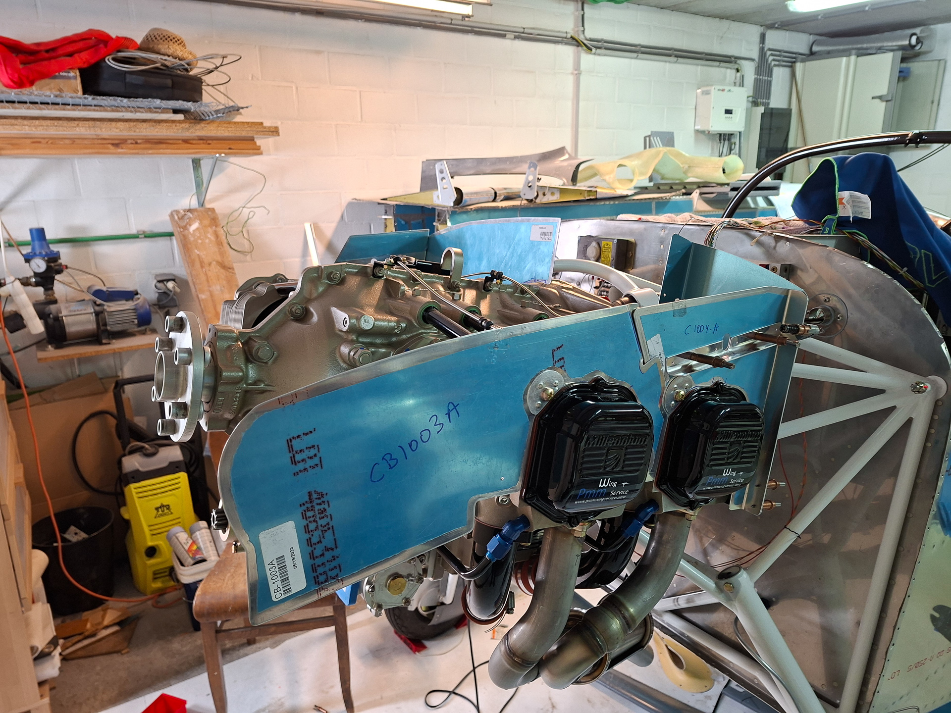
Installed the left pilot side front baffle CB1003-A
Then move on the the same piece on the other side called CB1009-A. More cleaning, more philing away material around the cylinder covers, 50 time on and off before finally being happy with the final fit.
Then installing the doublers on the 2 fastener locations.
With the 2 front baffles in place, I was curious how it would look like with the plenum on.
It's clear right away that the plenum will rest much lower and that this will seriously affect the position of the oil cooler in the back. A significant amount of aluminum will be removed from the upper side of the baffles. This is only an estimate but it will be at least this amount, possibly even more.
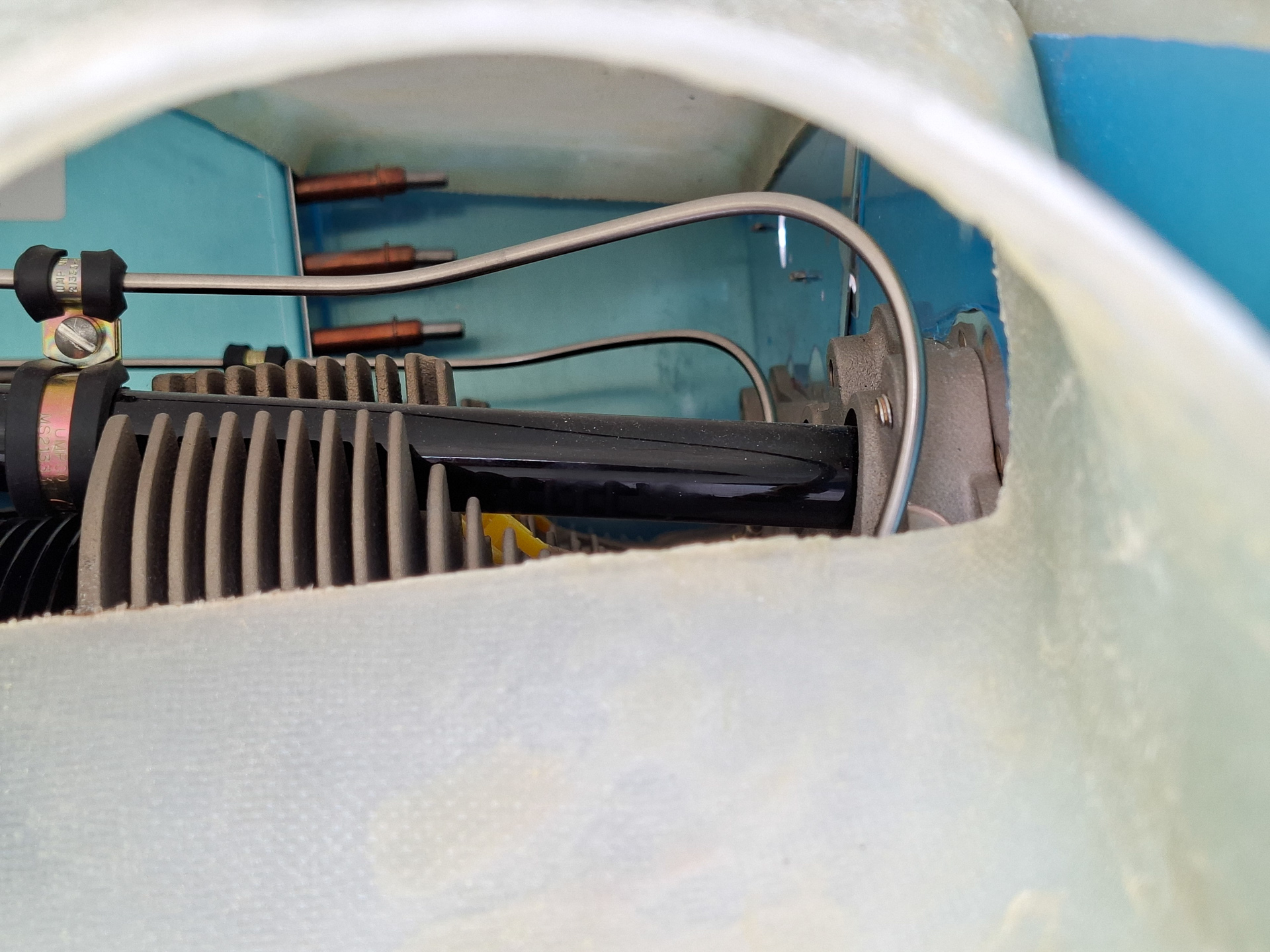
The picture below show a picture through the front air inlets. This will be even lower and it' s now clear that the clearance between the fuel lines to the nozzles and the ignition harness on the spark plugs in relation to the plenum will be very close. I read somewhere that it's recommended to used shorter spark plugs. I have to dig into that but will do that once I know if it's really necessary and the plenum height is defined.
Continuing on the forward air inlet baffles
The part on the left of the spinner. I'm sure this will have to be modified later on as Sam James has it's own air inlet and the ramps won't be required. It's unclear at this point which parts of the baffle kit from the front will be used and which are not used. At this point I may keep the vertical walls around the spinner and adjust the plenum accordingly but I'll have to discuss this with my DAR first.
Couldn't resist positioning the top cowl over the plenum to see how deep the plenum would have to sink to align with the top cowling. The top cowl is uncut and just resting on the crankshaft. I'll need to cut out the blue marked circle to see the actual fit. But it's clear it will still go lower.
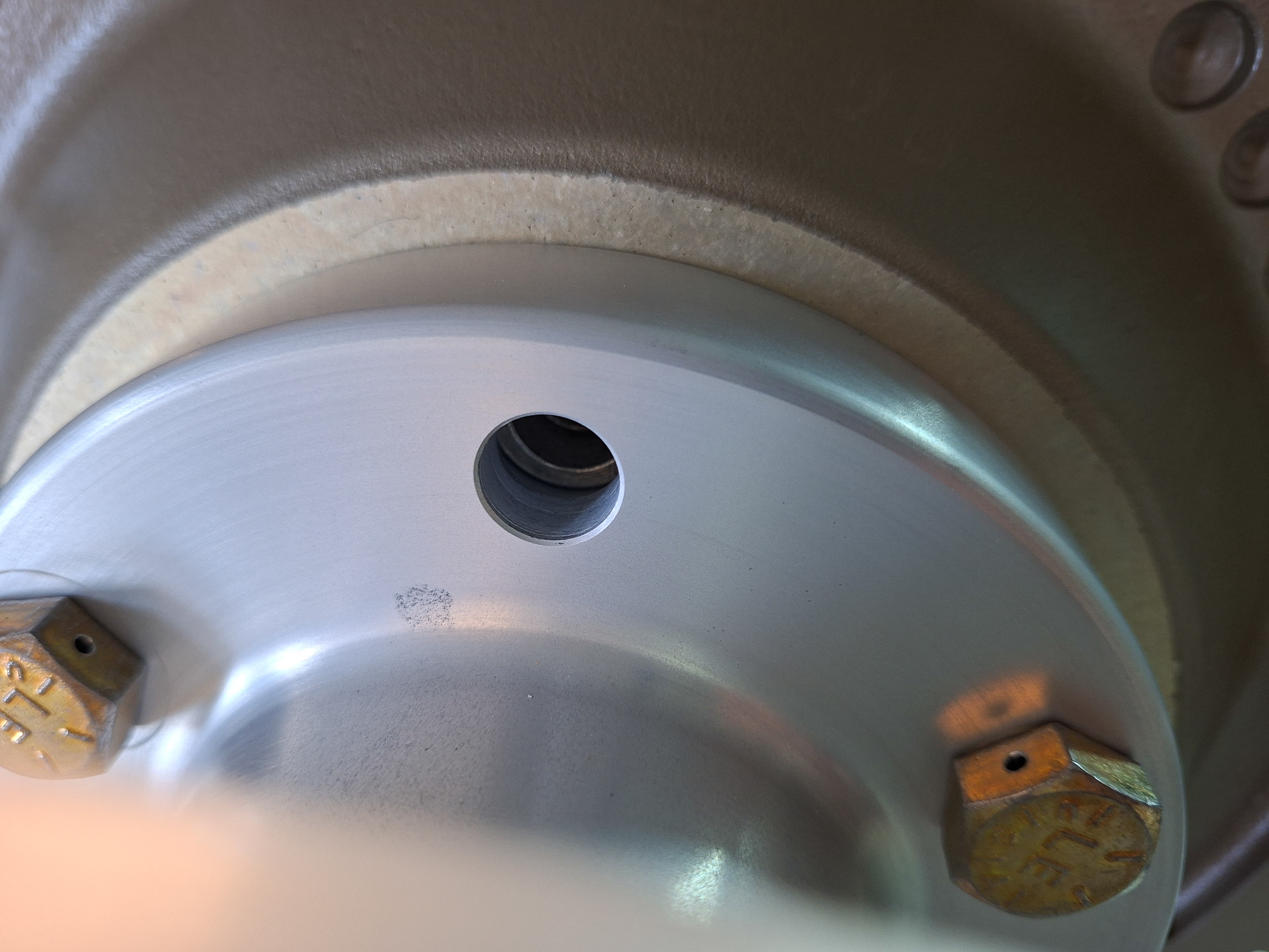
Another detail I noticed is that the lugs on the crankshaft are not fully filling the area available in the Saber Extension. The Saber Extension depth is about 0.6". The length of the lugs on the crankshaft is 0.6" but with the starter flywheel ring on it, only 0.34" is remaining of the lugs. That's probably normal but I'll have it confirmed
close up picture show this.
02/08/25 - Baffles continued (part 4) - 10h
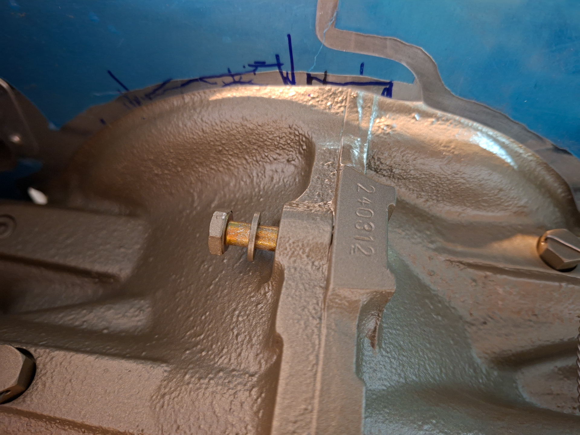
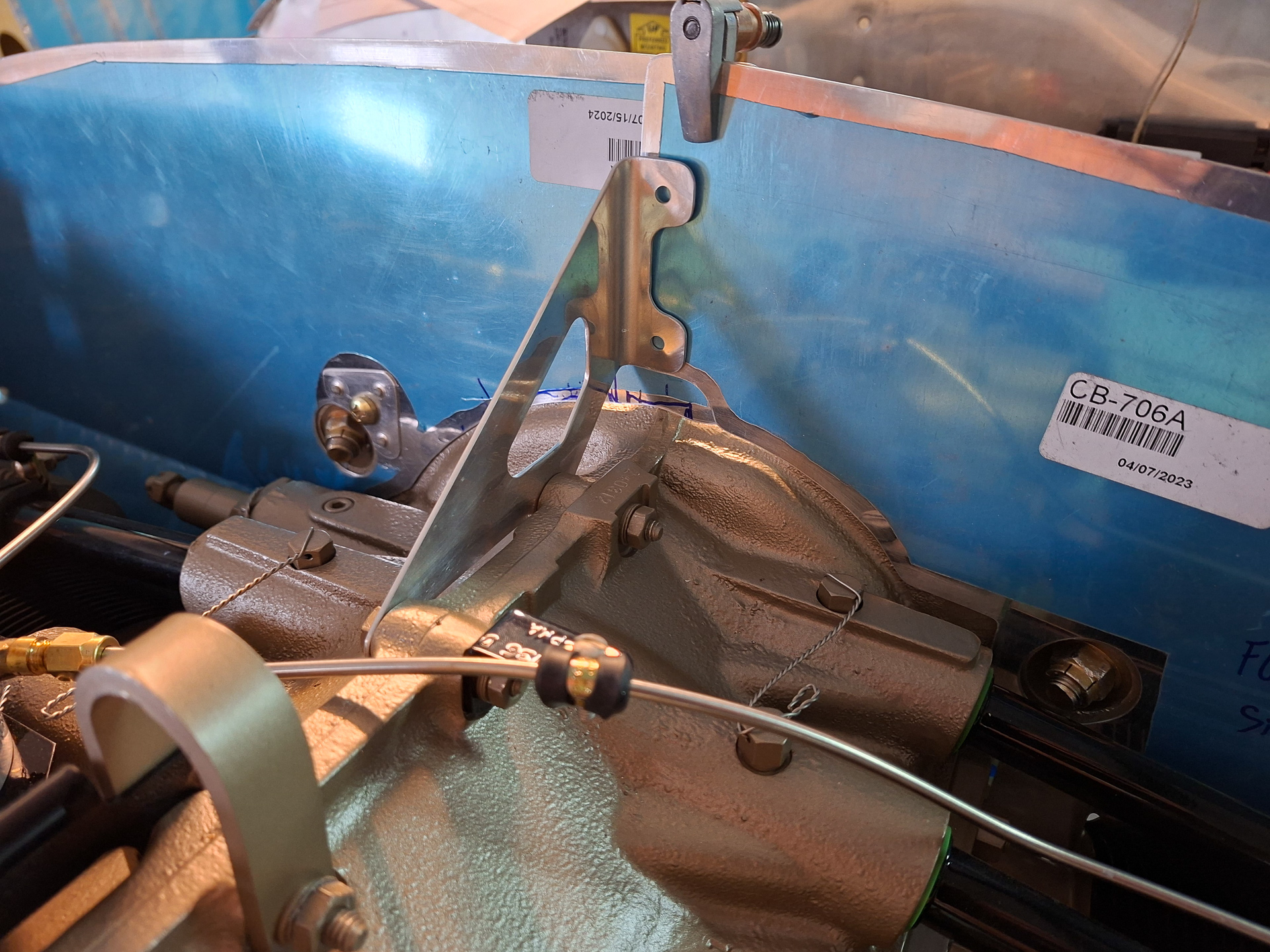
With the rear baffles on the engine, the plans tell you to install a bracket on the engine that supports the rear baffles. The triangular bracket is installed using two engine case bolts. It's a bit scary to unscrew engine case bolts. I unscrewd them and retorqued them to spec as indicated in the Superior installation manual appendix C.
Tihs is how it looks with the bracket in place. I'm still just following Vans baffle plans here. I'm not sure if this will be applicable with my Sam James plenum but we'll see that when we get there.
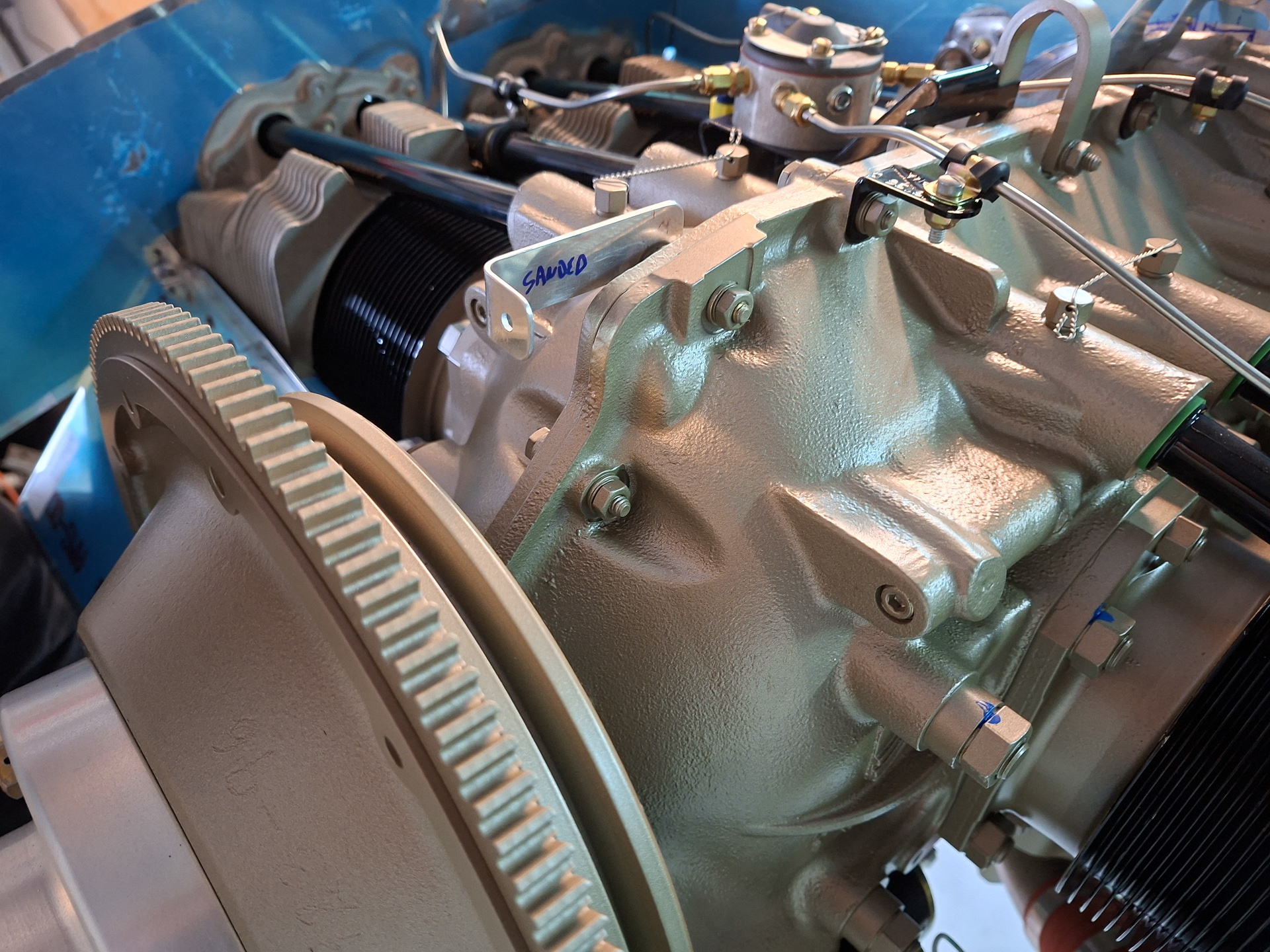
Another bracket is installed in the front of the engine just behind the starter flywheel. This bracket will support the forward baffle structure.
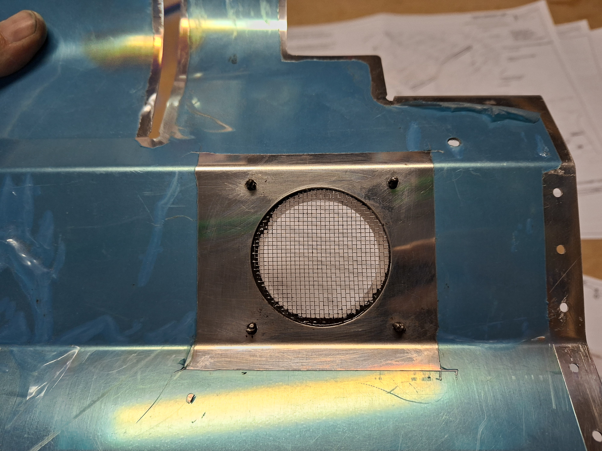
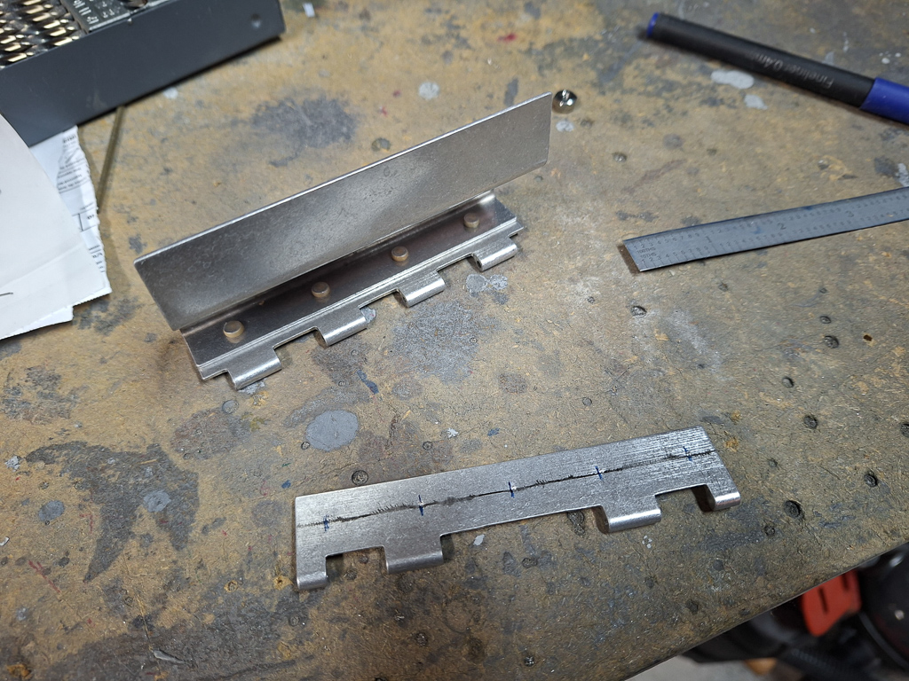
Next I cut out an opening in the passenger side rear baffle. This opening will guide fresh air into the exhaust muffle for heating air that will be redirected to the firewall heat valve. Used a flycutter on the drill press to get the correct diameter hole.
Then drilled the part that accepts a ducting over the drilled hole #30. There will be a mesh in between to avoid foreign objects to enter the heating system. The mesh will be prosealed in place.
Next I worked on the forward baffle pilot side. An angle bracket supports baffle and attaches to the engine case.
On the outboard side, a second screw attaches to the engine case near the cylinder head.
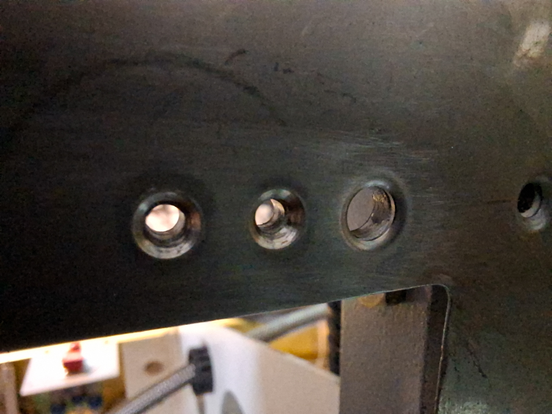
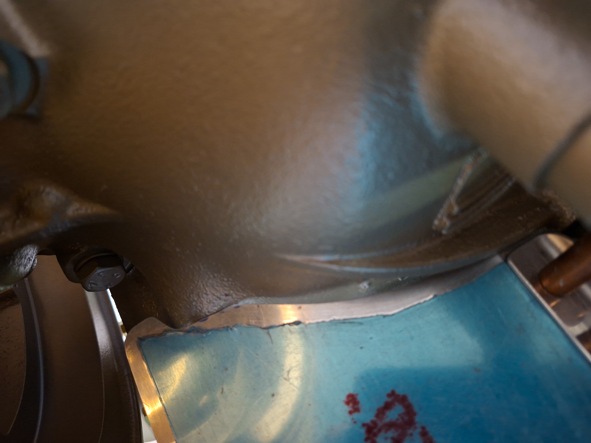
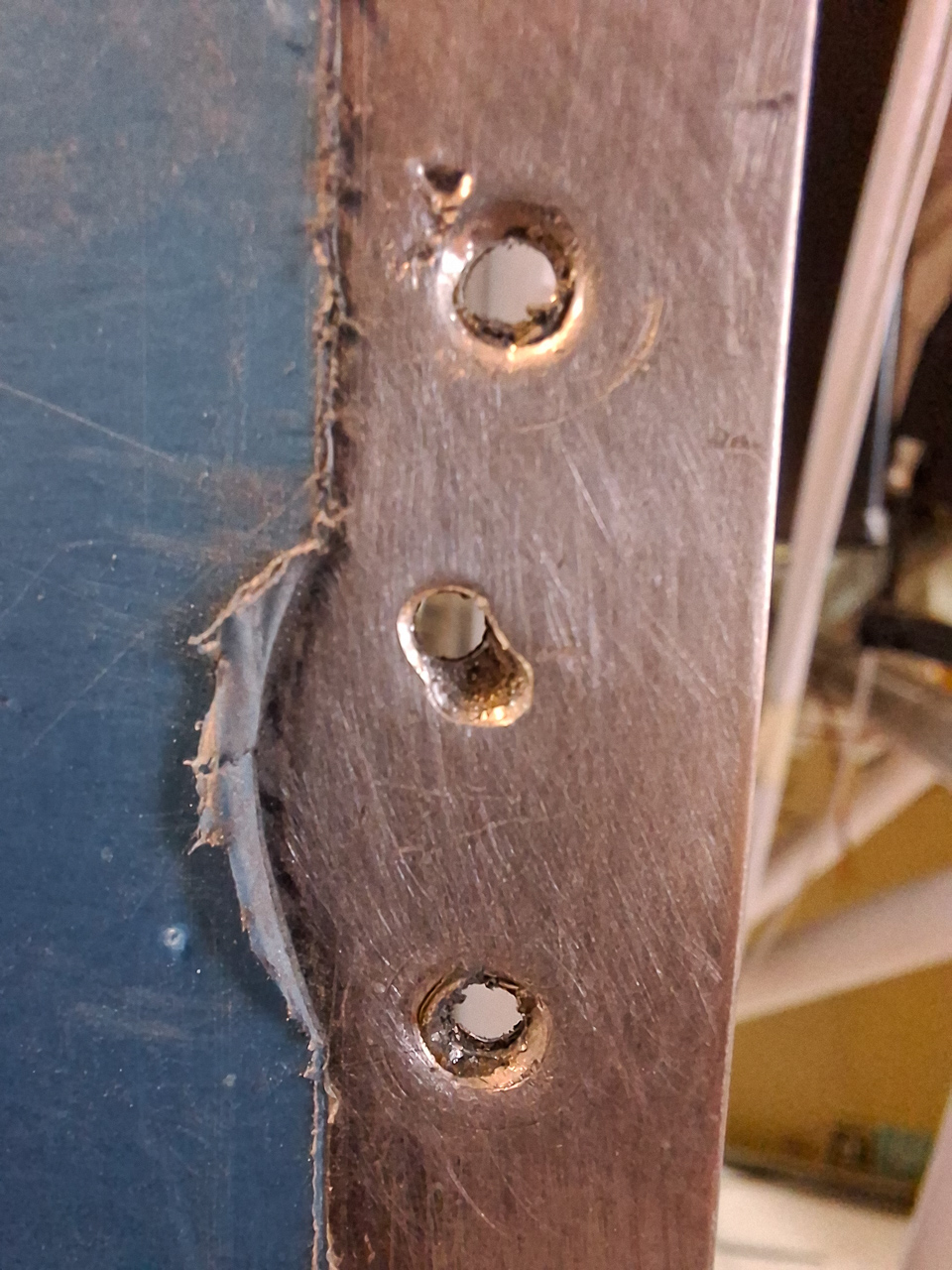
This is where I encountered another problem. The baffle bracket does not align with the engine case hole. I try to move things a bit but I couldn't get it even close. The macro image shot below shows the problem.
I realized soon that the probem originates from the inboard side. At first, I noticed the baffle interfered with the lower engine case and I started removing material from the baffle to align to the engine case shape. Lower left cut out in the image below.
It still did not completly solve the problem. As second measure I was able to re-bend the angular bracket supporting the baffle on the inboard side (see the angle top left in the image below) The material is quite thick and it took some work to modify the bend.
The image below shows the screw installed now on the outboard side.
Same part show below but from another angle showing both the inner angle and the outboard screw installed. When using the Sam James plenum, the 45° ramp up will probably be cut off later as the air intake with the plenum and Same James cowling is different than with the Vans cowling.
I had to further fine tune the part at the engine bottom. You can see the cutout below. I'm surprised that the Superior engine is any different in this place than the Lycomings.
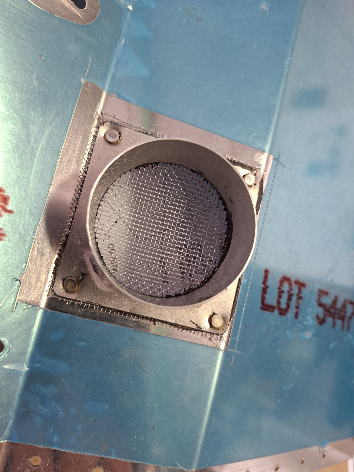
Finally I prosealed the mesh in the air intake hole. This will dry overnight and I can then set the 4 rivets. My pro-seal still dates from years and years ago and is way passed shelf date but it has been in the freezer and this is a non critical application. The 4 rivets will anyhow hold all together. I checked the next day and it still cures very well into the gooey substance it's supposed to be.
04/08/25 - Baffles continued (part 5) - 1h30
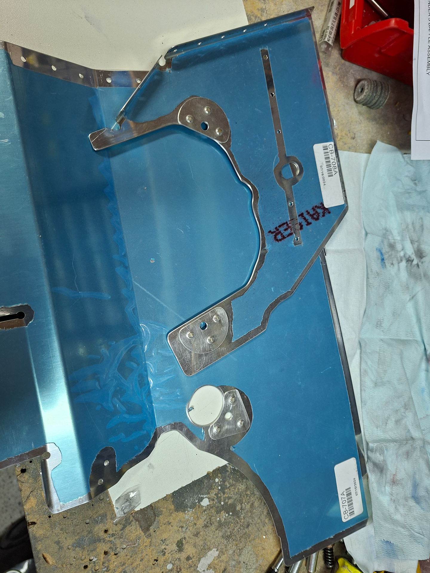
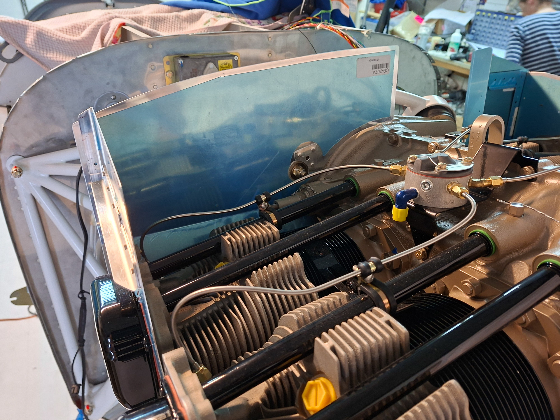
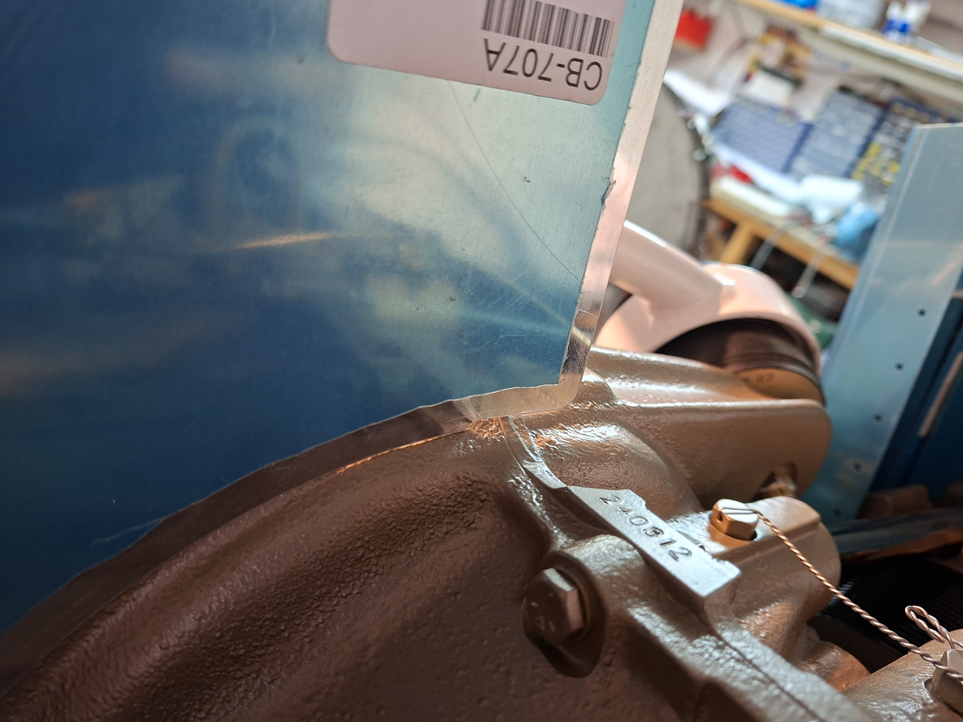
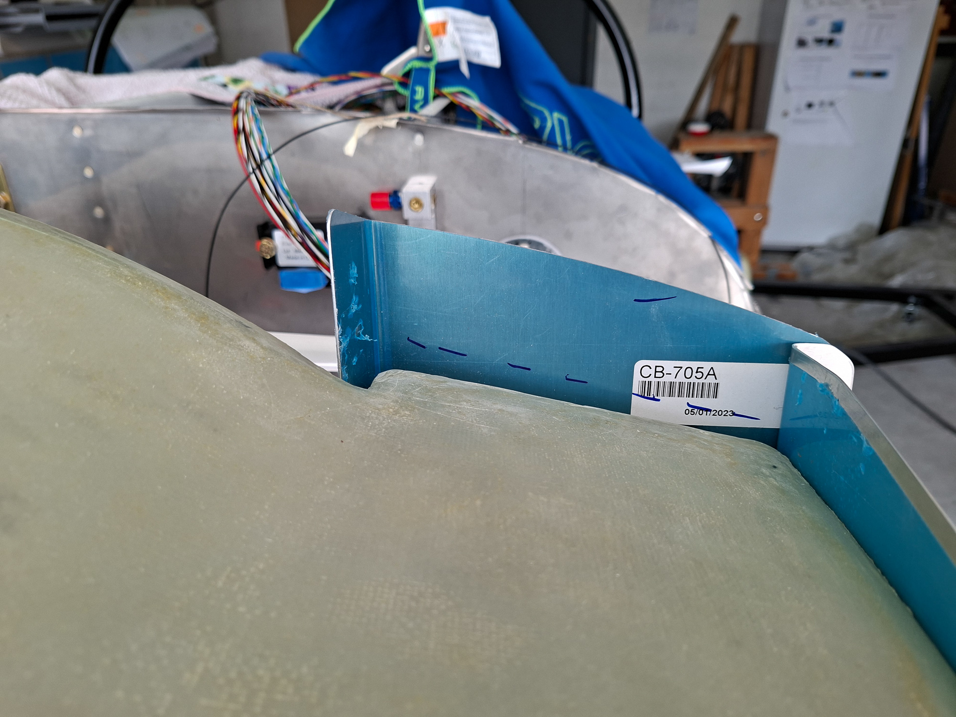
The proseal cured well so I could continue and rivet the Vent DL-3 part to the rear left baffle CB-707A using AN470AD4 rivets.
Re-clecoed all parts together and admired the result.
This is as far as I can get things on the baffle installation kit. Next step would be to decide how to adapt the front ramps and the baffles behind the spinner to fit with the Sam James plenum. In order to get the plenum in place, I need to know the position of the cowling inlet rings as these mount directly to the plenum inlets. So everything points in the direction of installing the cowling at this point. Unfortunately I can't the top fuselage skin yet and it's not clear if I can match the cowling without the top fuselage skin in place. Will have to deliberate a bit further on this. As top fuselage skin closing is coming closer, I might continue in the next steps on finalizing some more electrical wiring organization and installing more clamps. Also thinking of the remaining electrical wiring from the EMS module to go to the firewall forward side. I can already install pressure senders and oil temp sensor so that will also be on the task list for the next days.
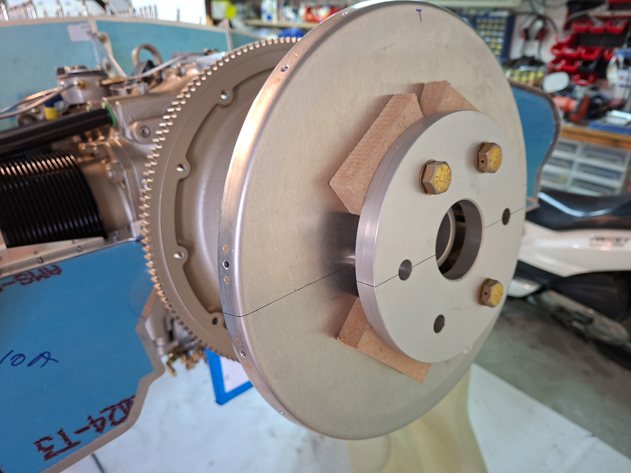
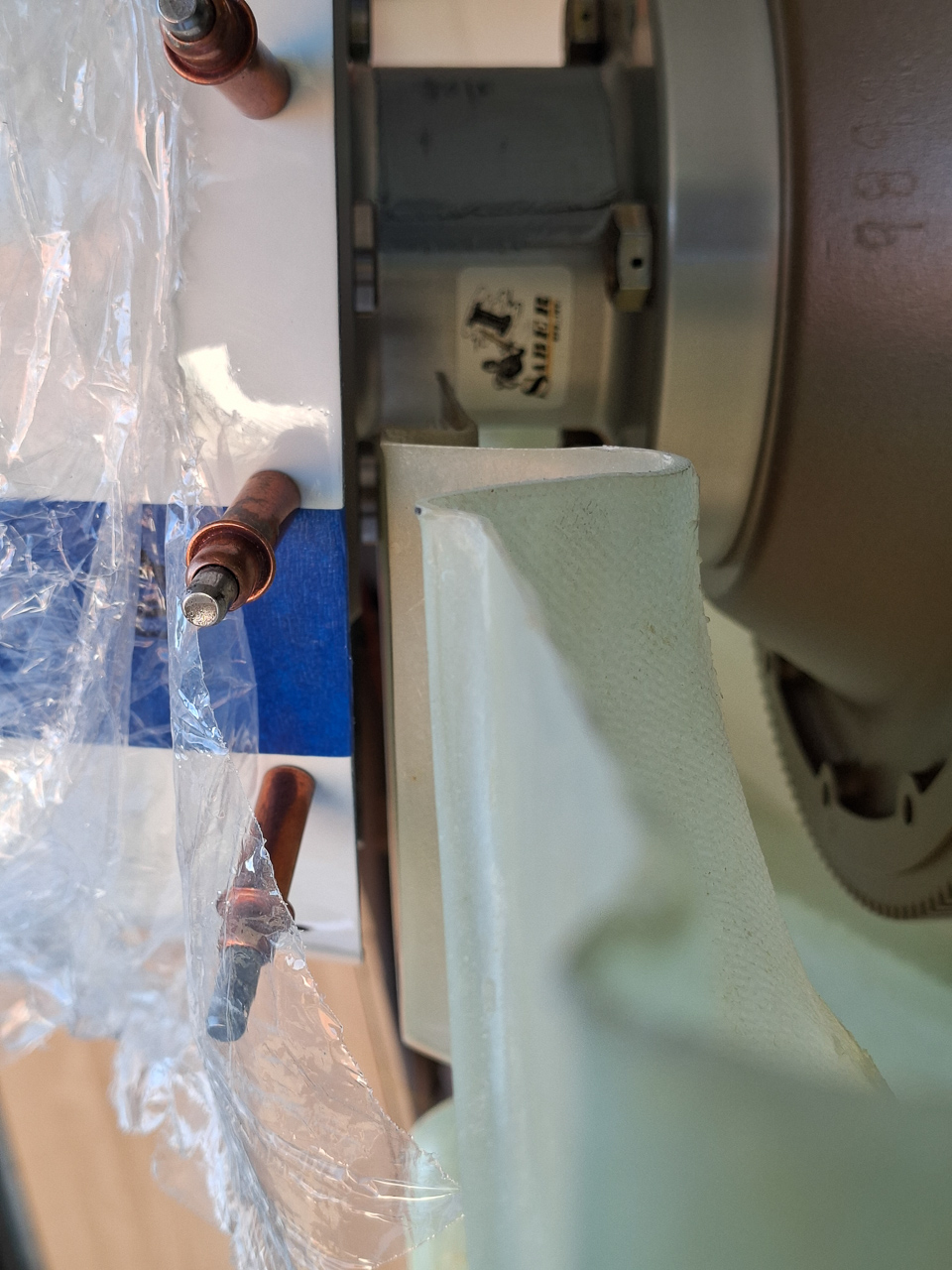
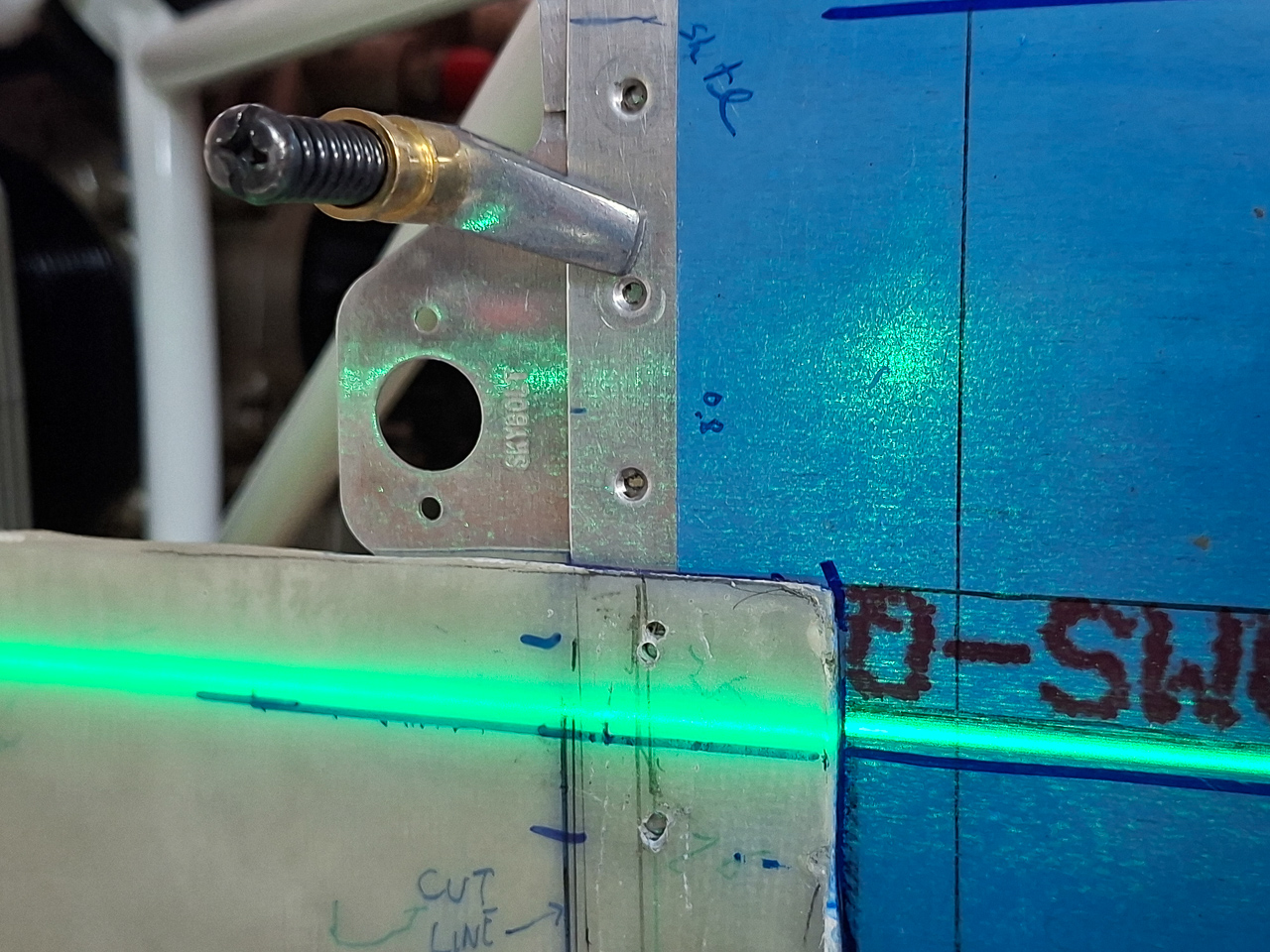
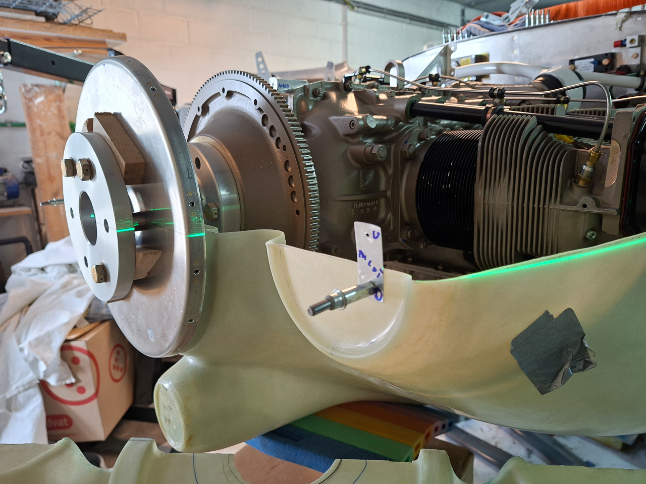
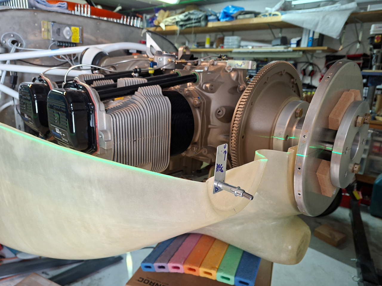
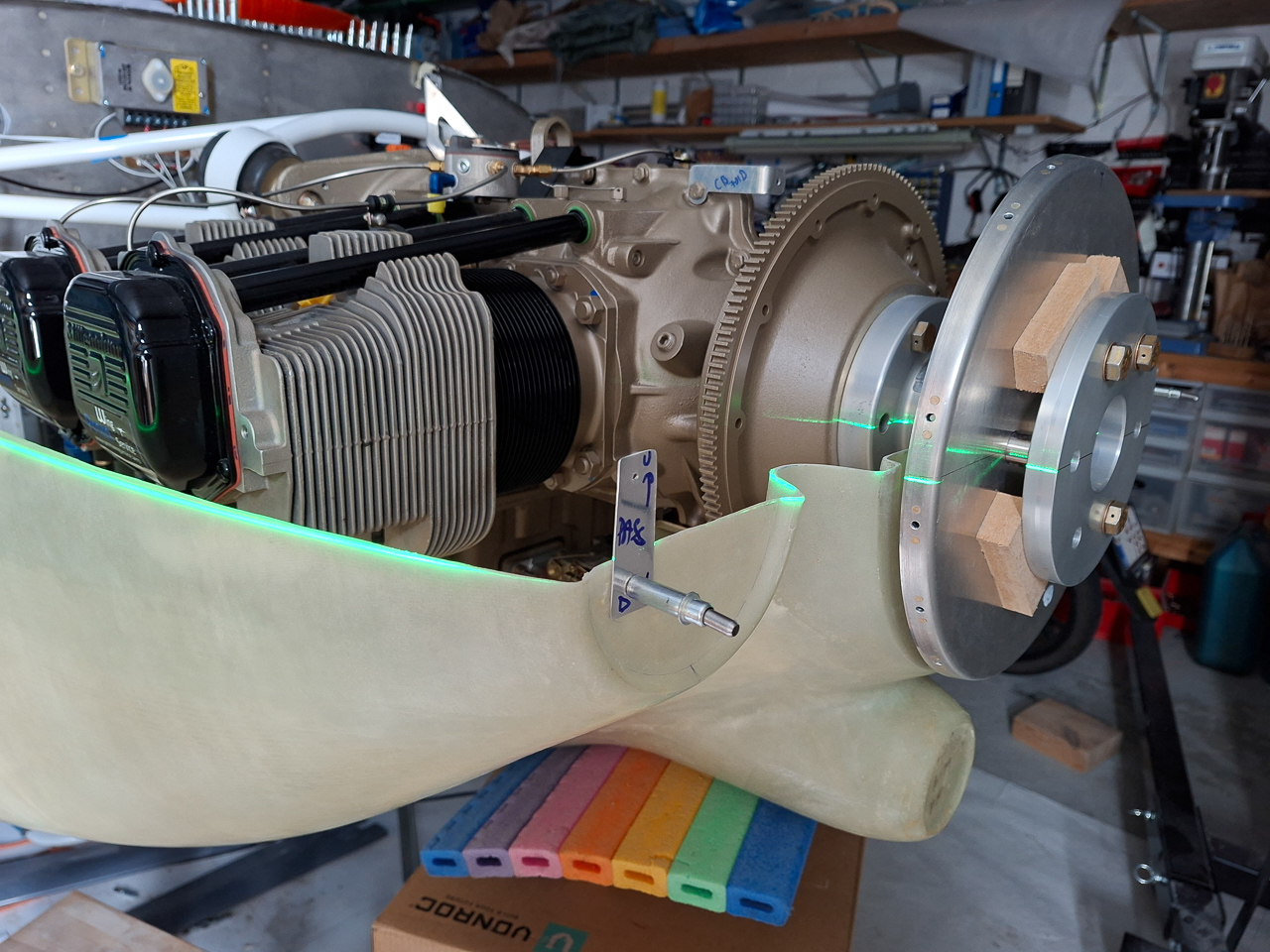
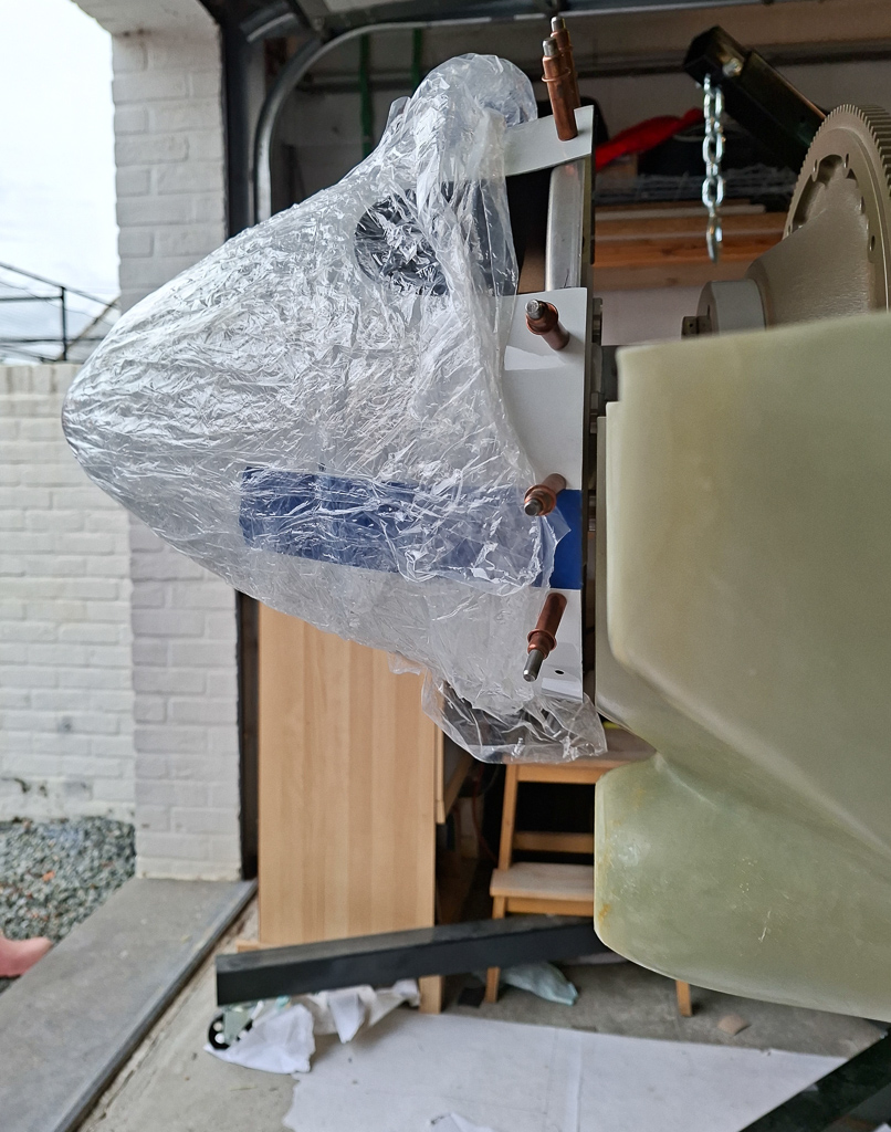
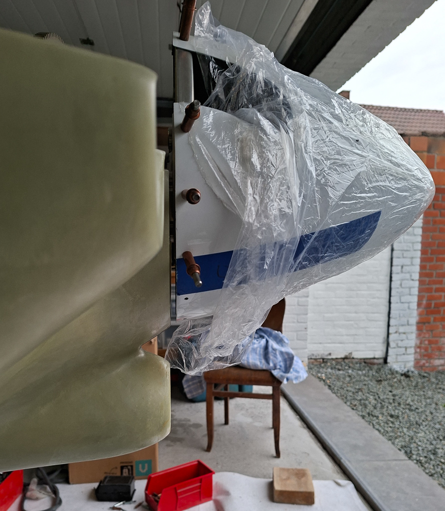
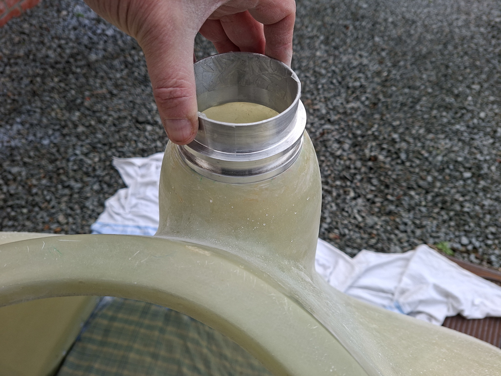
13/08/25 - Test hanging catto prop first time - 1h
A big day again in my project. Nothing substantially done but I have hung the propellor on the engine prop hub for the first time. I kind of wanted an idea how everything would fit together and what is delivered by Catto with the propellor, spinner and saber extention.
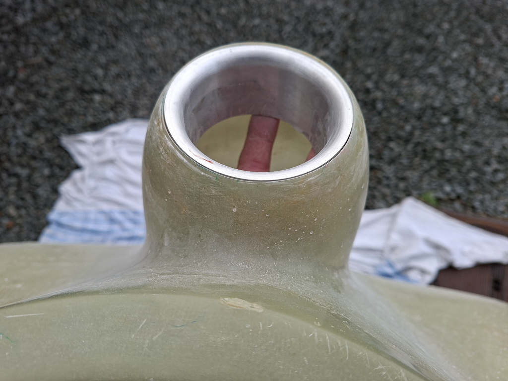
I have a 4 inch Saber extention, spool type. This is required for the Sam James cowling installation. It took a couple of tries to find the way to do this but it's pretty self explanatory once you understand things. The spinner is predrilled and cut and the holes in the spinner plate are also made with nutplates installed. This makes it pretty simple.
Short bolts hang the spool to the prop hub behind the starter flywheel. You bolt these in in a star pattern. I am just doing this temporarily so there is no torqueing involved yet. This will come of a zillion of times. The long bolts holding the propellor and everything forward of the spool extentions are very long. The threads also extend quite far through the extension. This is probably for having enough space if an additional weight plate has to be added up front.
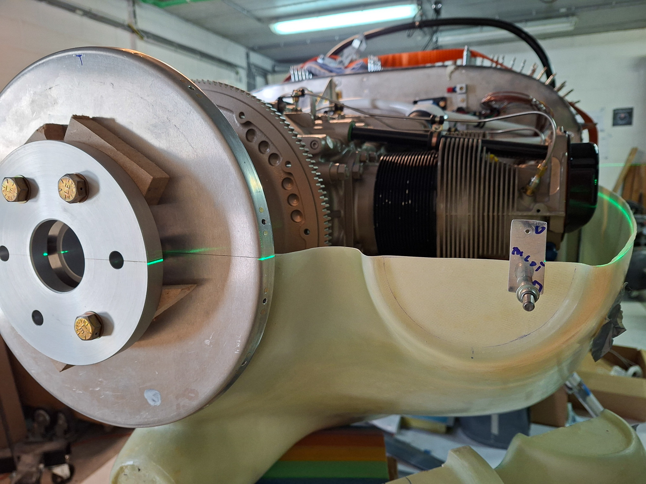
Here is a view with the prop bolted on. This is pretty damned cool seeing this a first time.
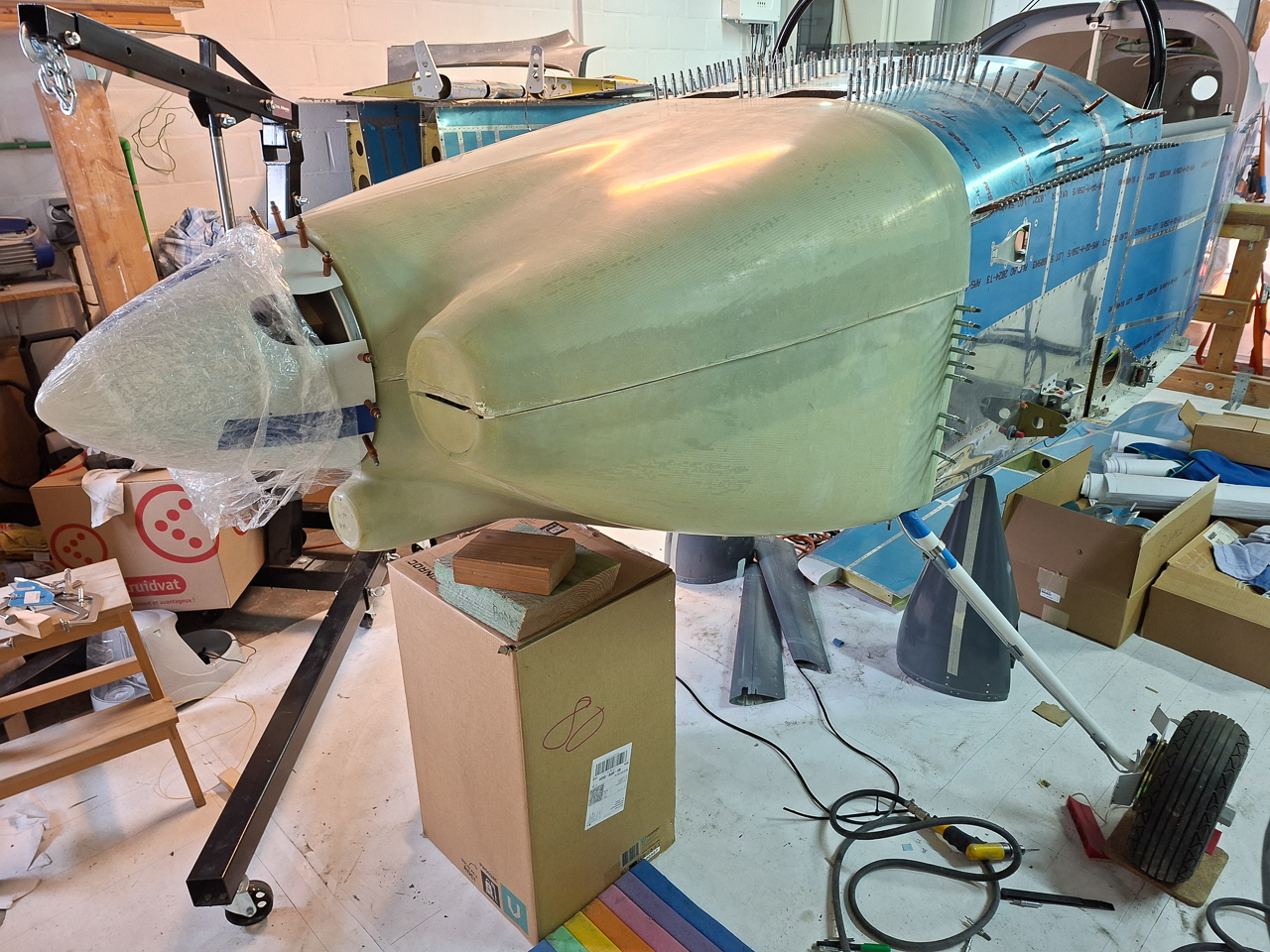
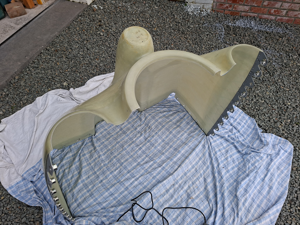
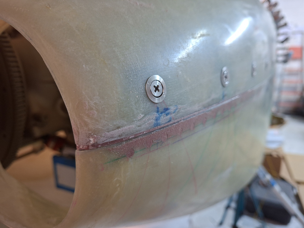
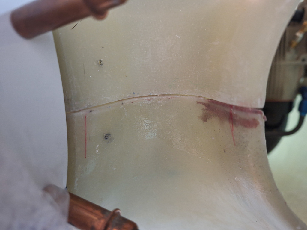
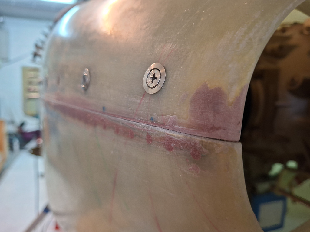
For a long time, I was skeptical about hanging the cowling, influenced by other builders who described it as the most dreadful part of plane building. The process involves fitting, cutting, hanging, and repeatedly filling pinholes with epoxy, sanding, epoxy, sanding, epoxy, sanding, epoxy, sanding, and more sanding—a truly memorable challenge. With this in mind, I began researching how to approach the cowling.
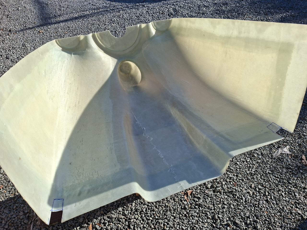
My cowling is not the standard Vans cowl but the Sam James Long cowling by James Aircraft. I also bought the induction kit that goes with it. I have a 3 blade catto propellor which requires a 4" Saber extention (Extension 4 in. long, 7 in diam, 12-hole, SAE-2, 1/2E. Crush Plate) in combination with the Sam James cowling.
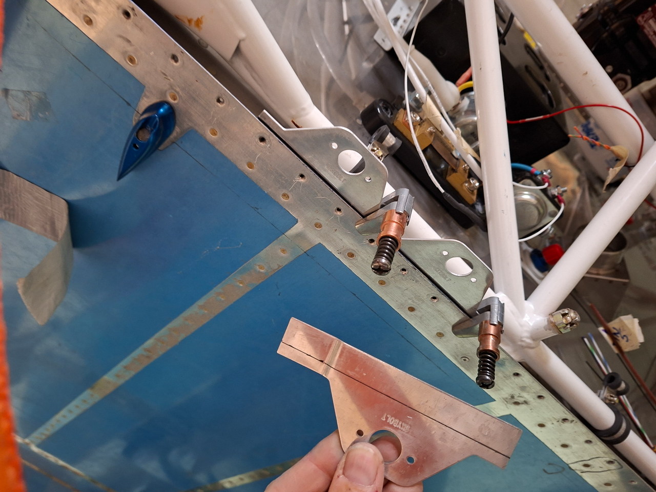
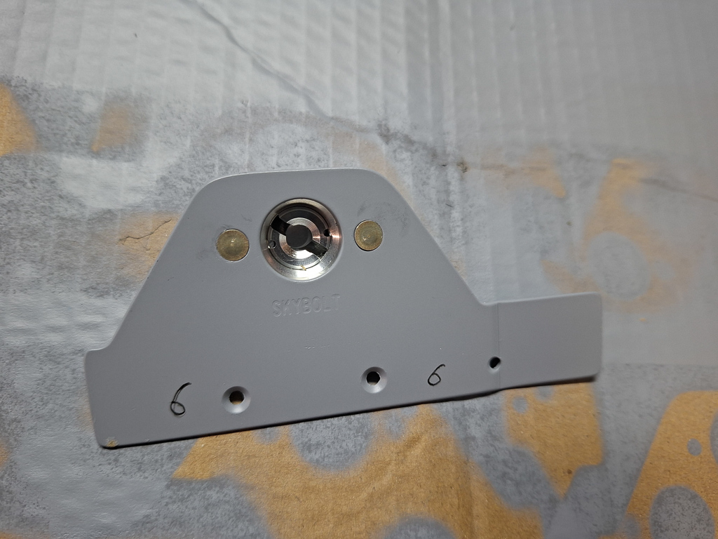
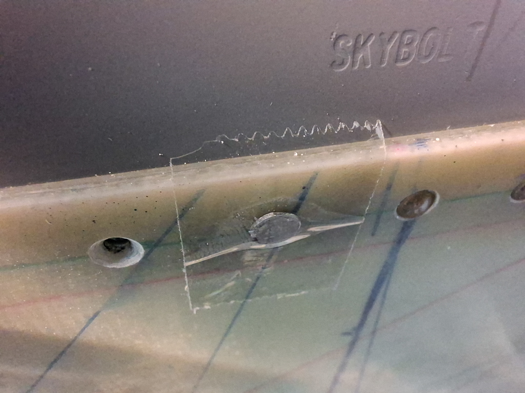
I have read the manual of the Sam James cowling but I found it rather cryptic and not easy to ready for a new builder. I also had purchased the CLoc Skybolt fastener system , which has its own manual. After reviewing the vans instructions on their standard cowl, the Sam James manual and the skybolt manual, I decided that I would go with the Skybolt approach. Their manual is great and instructions clear. Much of the work is similar. The manual of Skybolt can be found here on their website.
I also found great resources on kitplanes.com. More in particular a series of articles written by Larry Larson also known as WireJock - a well known contributor - on the vansairforce website. The articles explain the Skybolt installation approach step by step by using a propellor jig. Read the 2 most important articles here: part 1, part2.
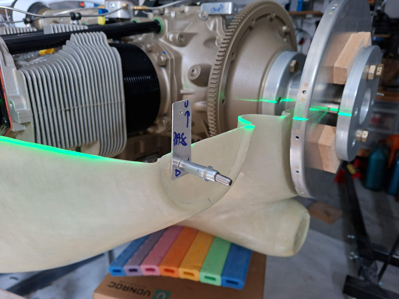
I decided not to spend a lot of time on making that jig. My catto prop has the advantage that the spinner back plate is already cut and balanced. The holes for the spinner are match drilled with the spinner already. I verified that earlier by temporarily installing the prop on the saber extention. It all fits very nicely. So for the crucial spacing behind the spinner (which should be based on the back of the spinner, I will use the spinner back plate.
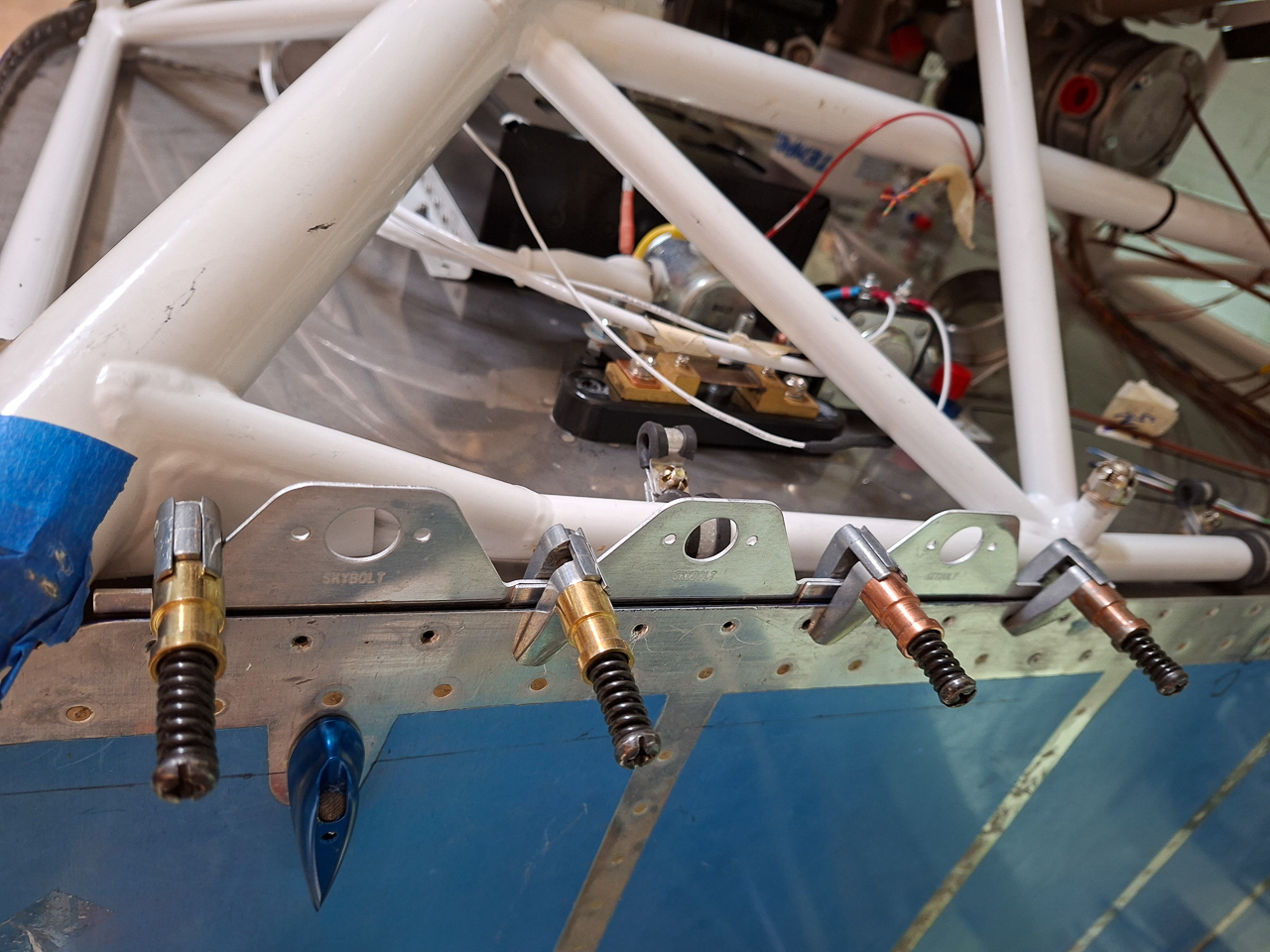
The propellor would be terribly in the way each time the cowl has to come on and off again. And believe me, this will be done a hundred times. So you have to get rid of the propellor but still be able to have the back spinner plate in it's acurate position.
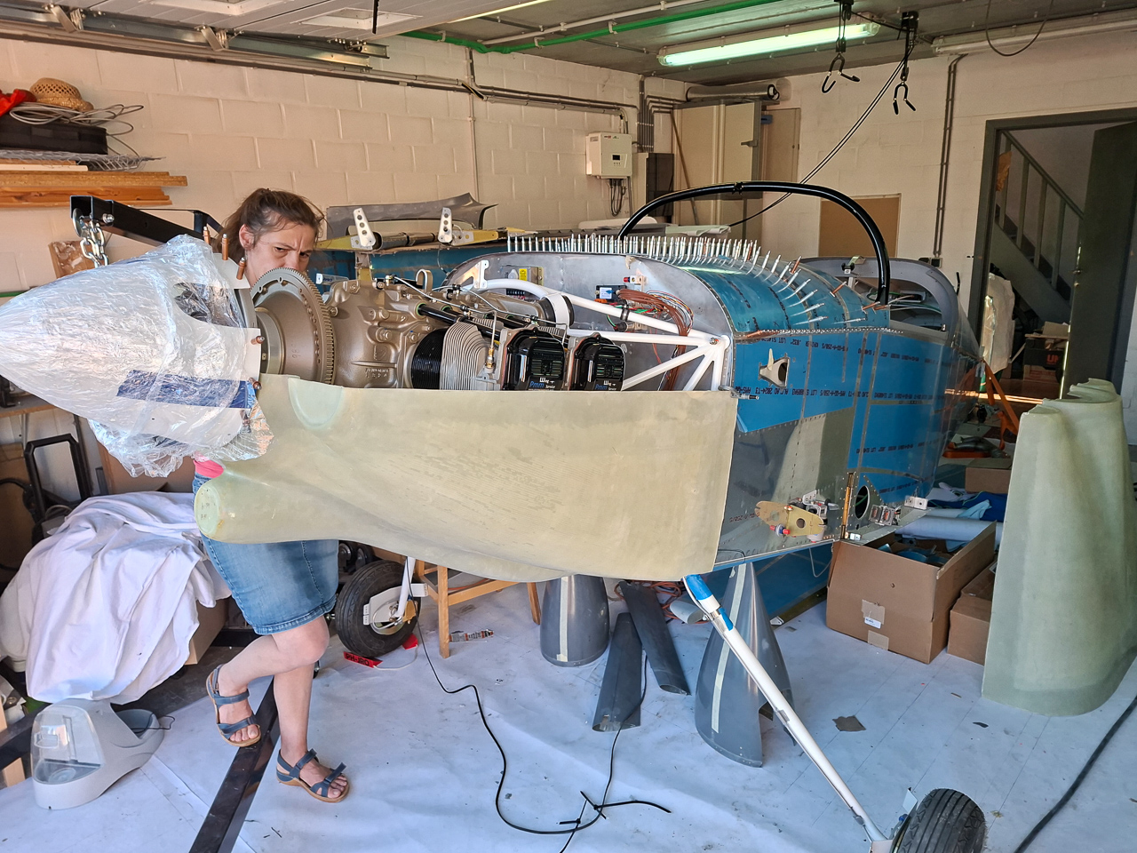
The order of installation of the propellor is : the saber extention, then the back plate, then the prop, then the crush plate, then the middle spinner plate and then the spinner over it. The annoying thing is that you can't just hang the spinner back plate without installing the bolts. The bolts are too long to be used without the prop. I though of this simple trick to mimic the presence of the prop. I used wood blocks of similar thickness to squeeze between the spinner plate at approximatly the location of the prop extention hub and mounted the crush plate above them. The screws now engage far enough so that I can pull is all together such as it would be if the prop would be there.
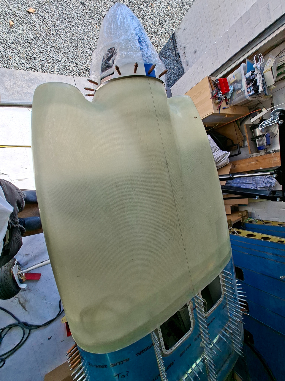
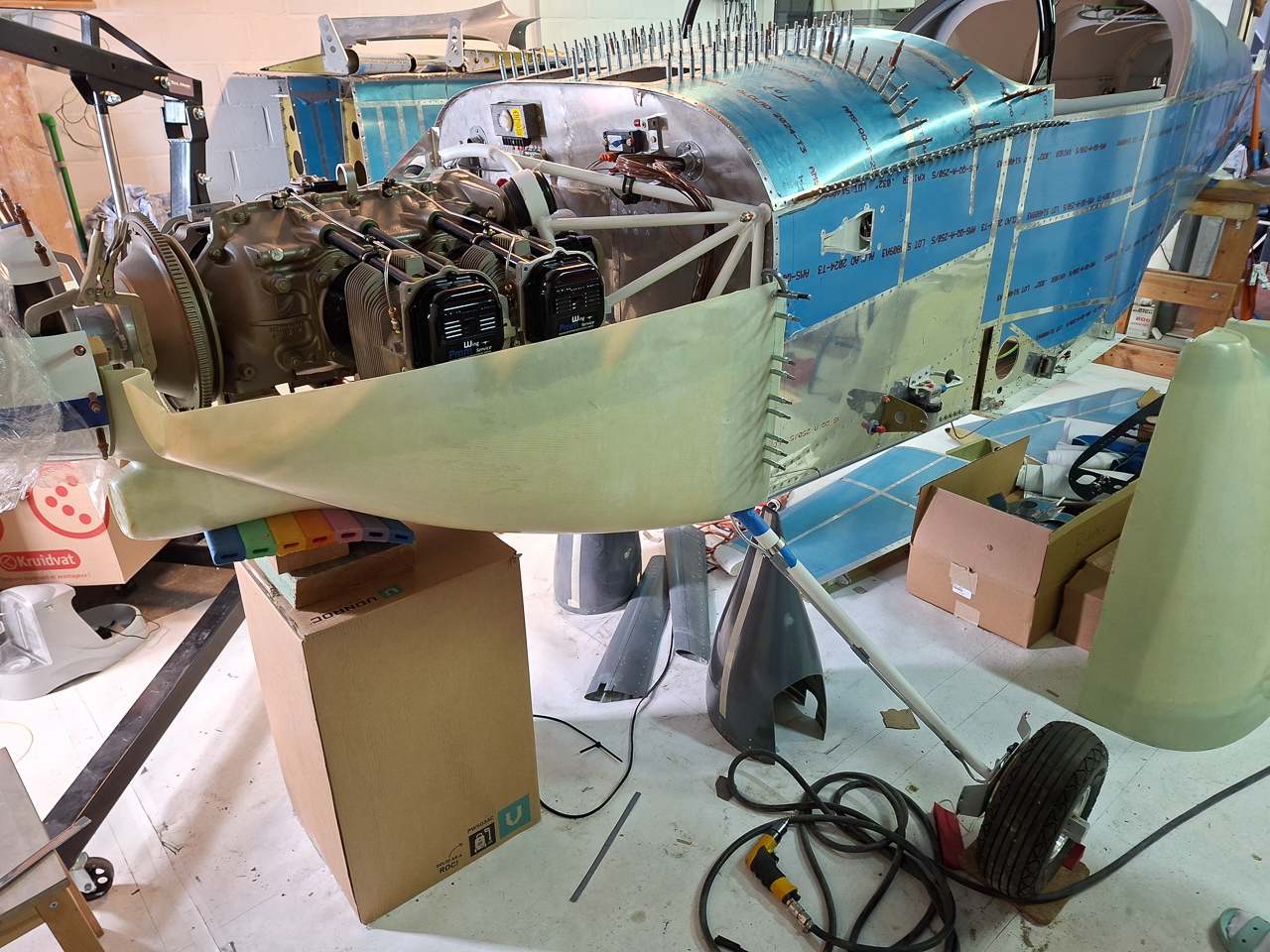
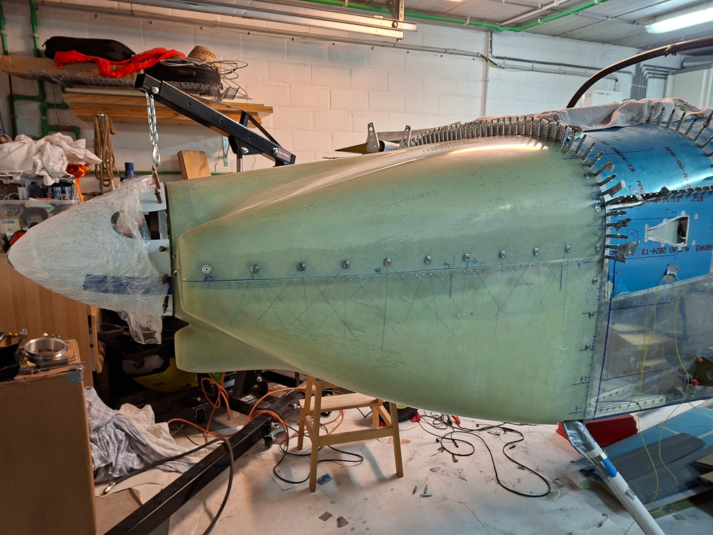
This is much more compact than having the propellor in the way. As the spinner is drilled by Catto, I can just cleco them with #30 cleco's it in the nutplates on the side of the back spinner ring.
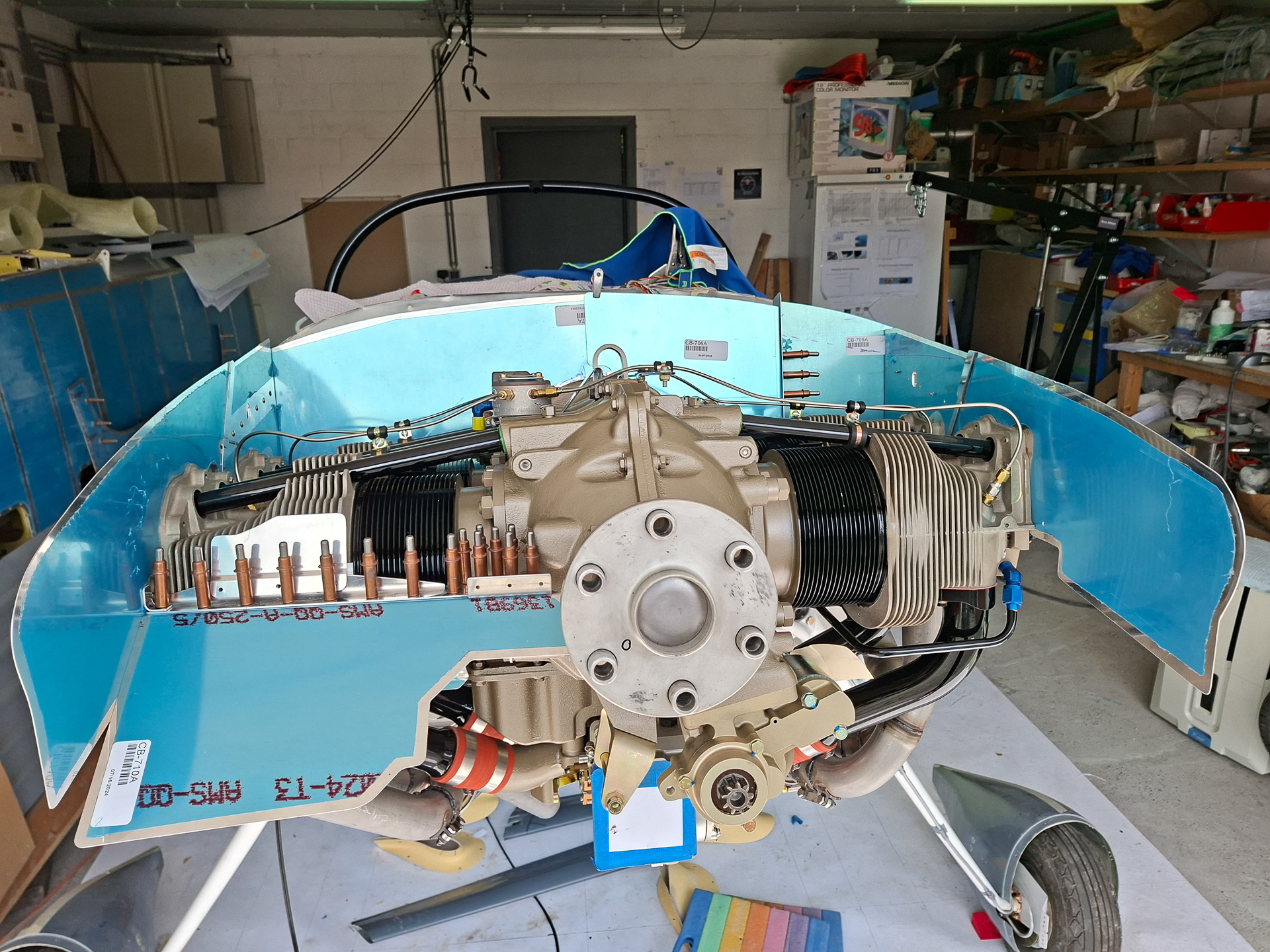
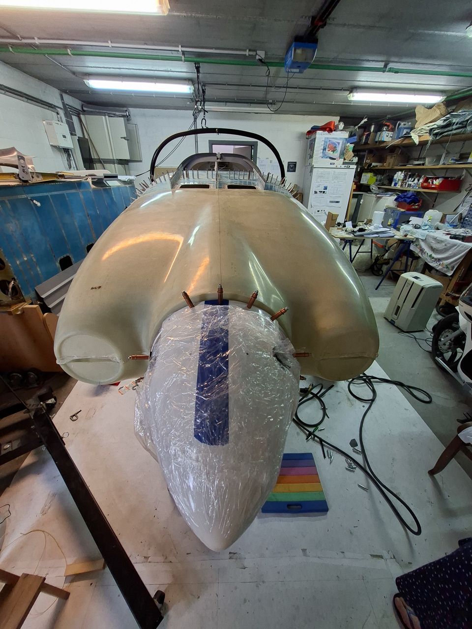
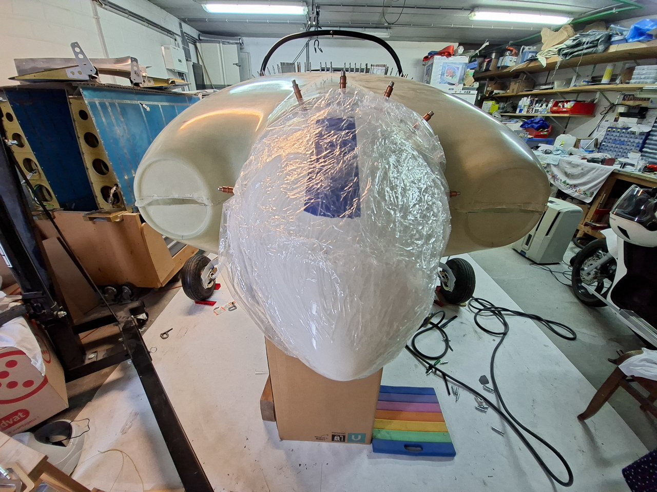
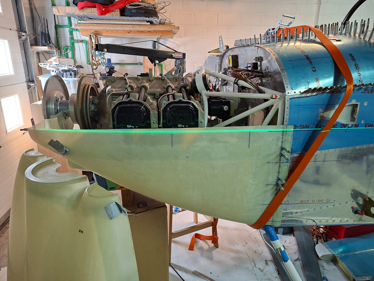
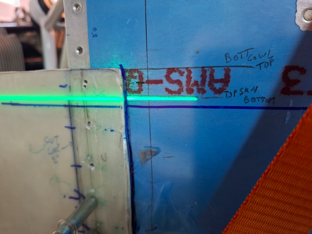
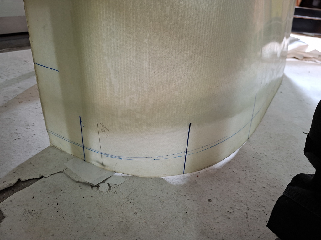
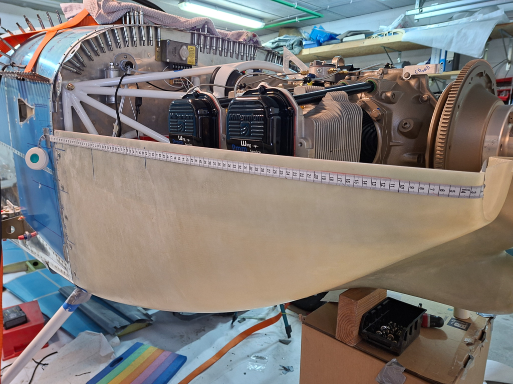
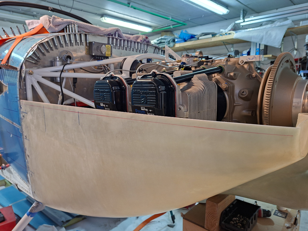
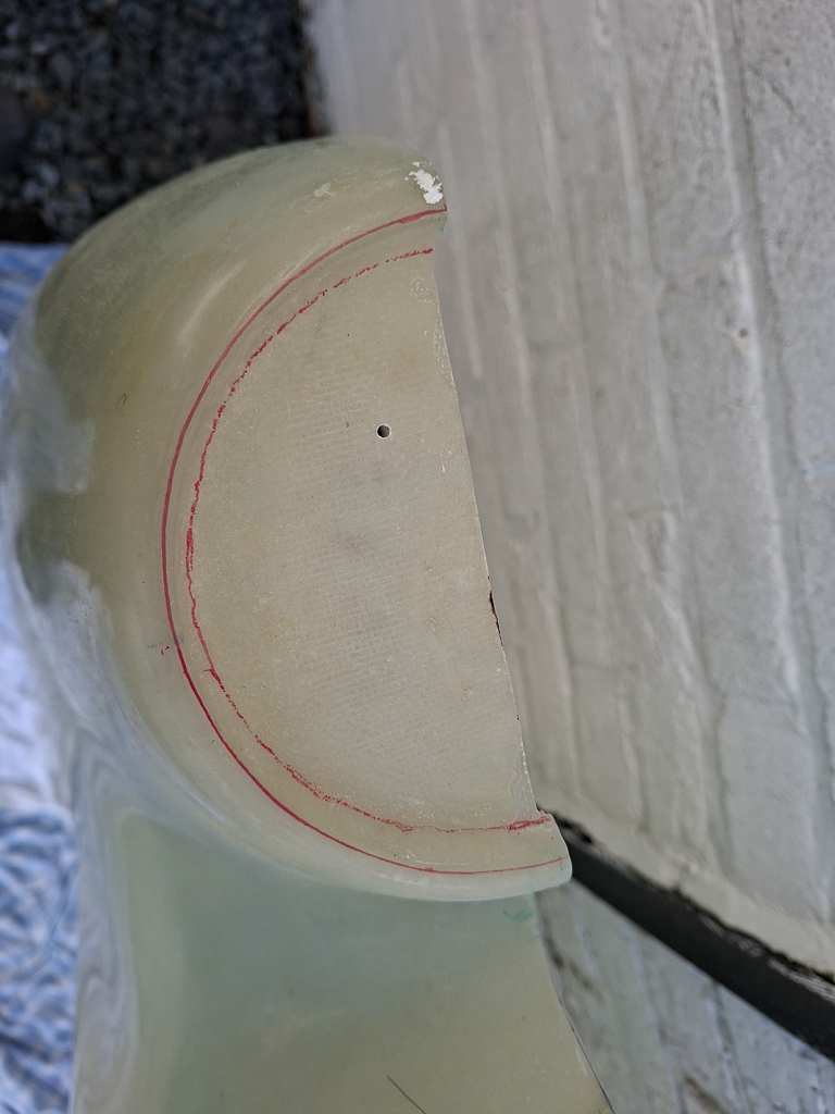
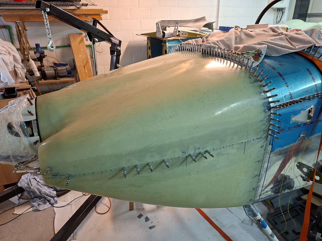
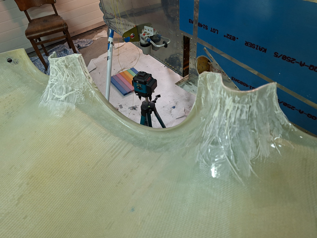
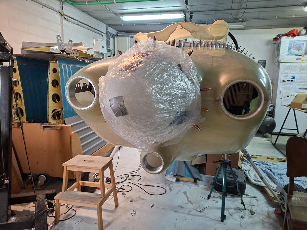
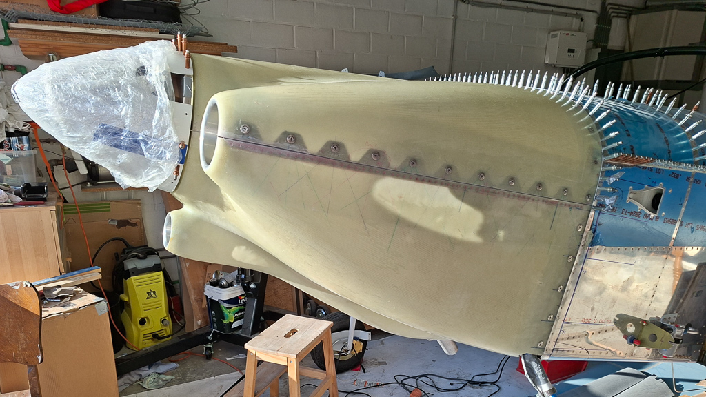
I did this in the picture below and couldn't resist placing the top cowl over the engine. It looks really nice. I also used this opportunity to draw a center line on top of the top cowling by using the middle of the fuselage as a reference point and the middle of the spinner. A double check can be done to assure left and right are at the same distance from a "level" point. (put a level on top of the spinner and measure from the level to the top of the air intake rings).
Another shot from the front.
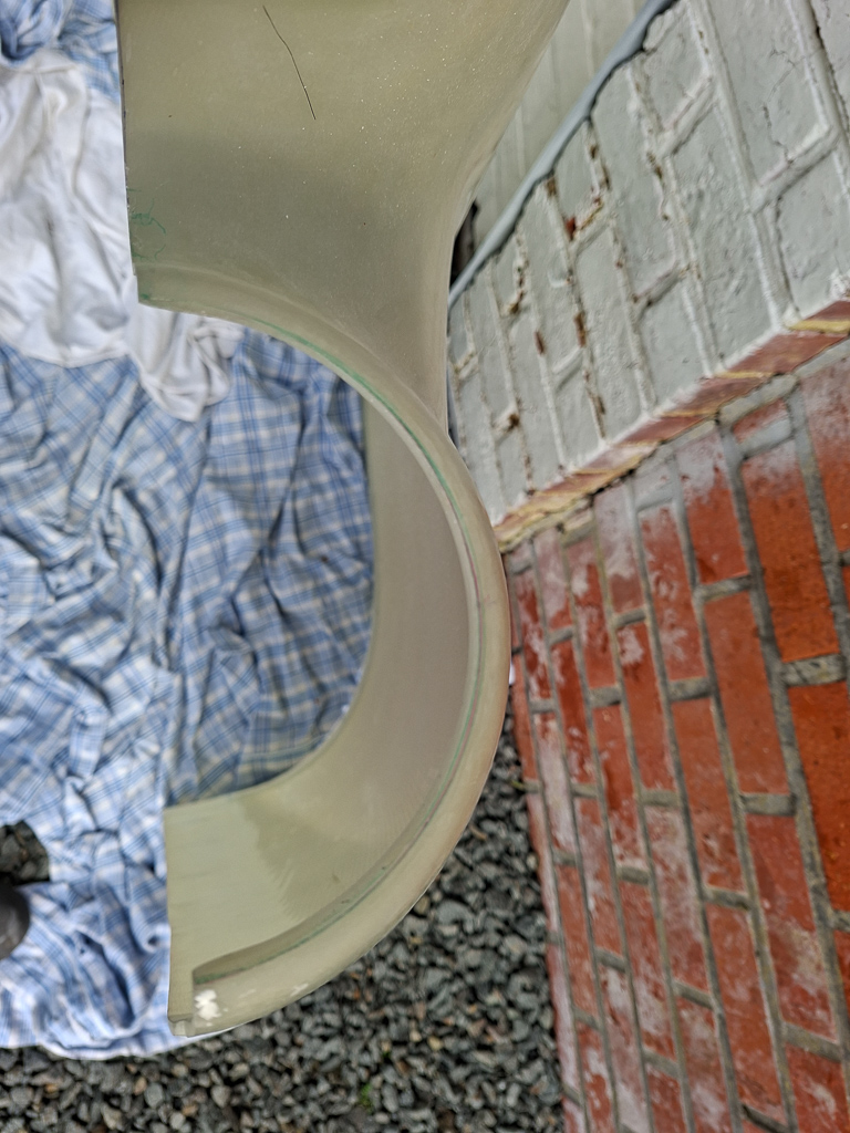
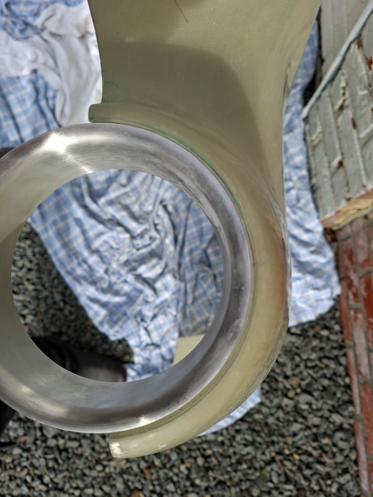
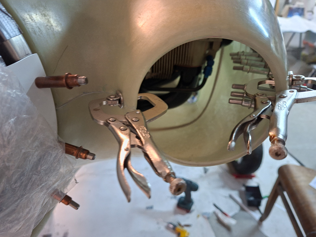
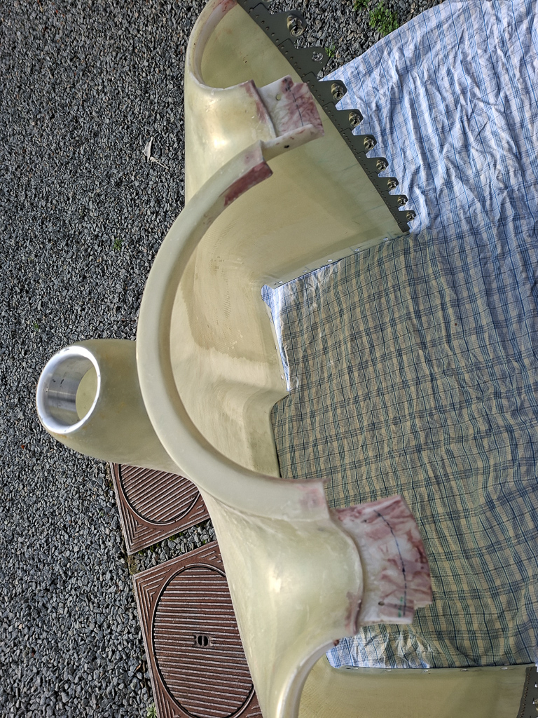
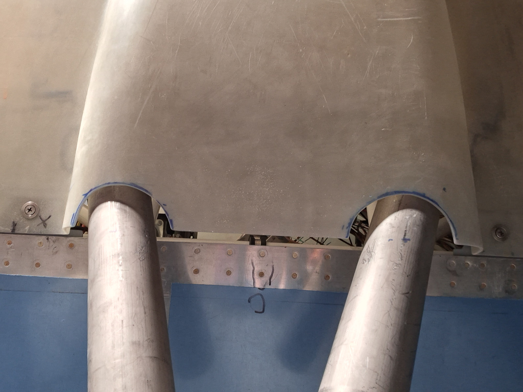
Next I cut some holes in the lower cowling in order to clear the landing gear legs. This is a repetitive process of checking and cutting more. The brake lines are really annoying at this point as they kind of sit in the way all the time. In order to slide the cowling under the spinner, you need to move the whole cowl a bit more backwards than it will be in it's final cut state. My cut out may be a little to large in the end but this will be covered with gear fairings and I will probably add some new epoxy when all is ready to make this hole as minimal as possible.
Cindy helped to hold the bottom cowling each time I got it on and off. It's very difficult if not impossible to do this on your own.
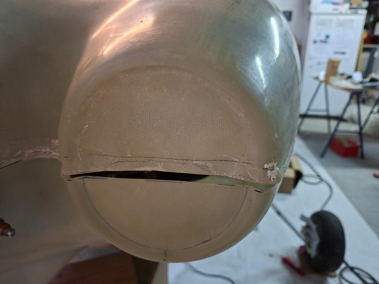
As you can see here, the front hole is slightly oversized but the cutout is really needed at this point to clear the brake line when sliding the cowling from underneath the spinner.
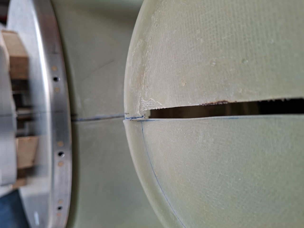
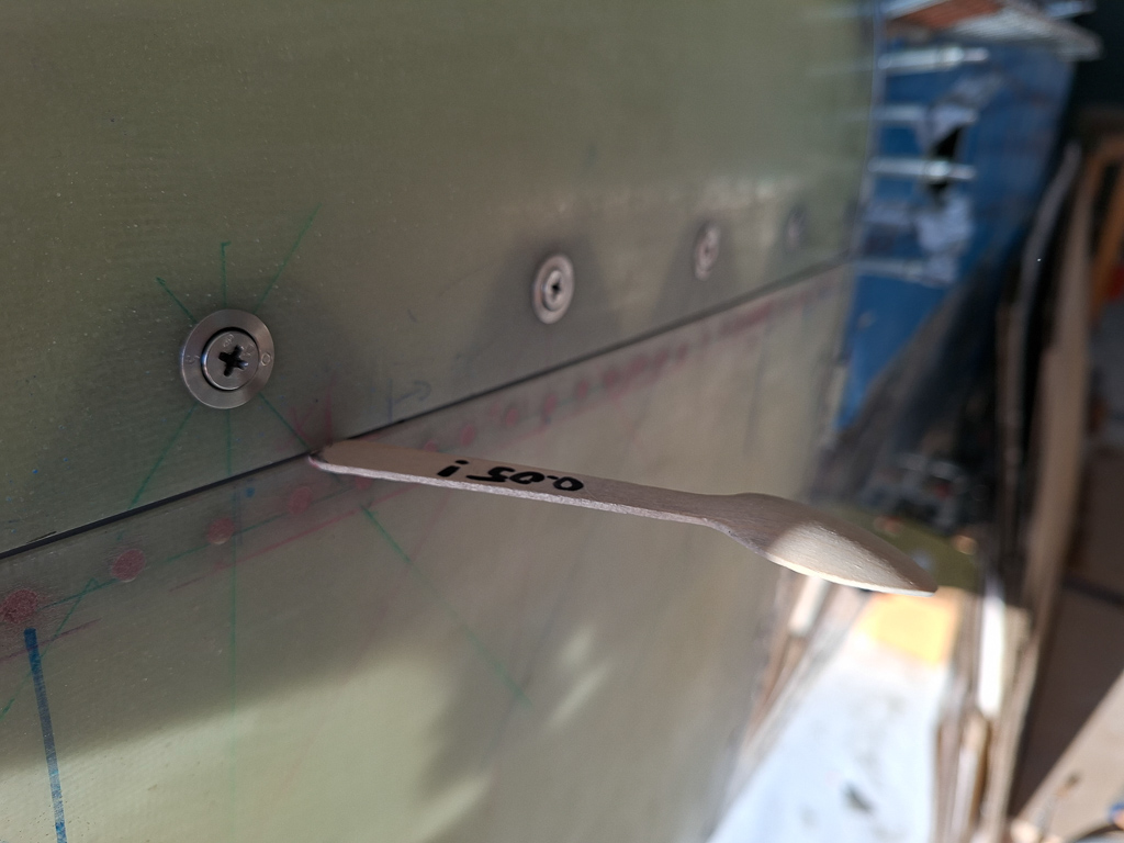
I'm just holding the cowl by hand at this point, but the gap shown in this image is what you will be looking at during every trial fit. The distance between the bottom and top of the cowl needs to be equal at about 0.25" all around. (left side, right side, bottom and top).
The cowl is obviously too low at this picture. The transition of the spinner to the bottom cowl is equally important.
Starting to get the picture ? Precision and patience are going to be crucial for this high-accuracy task.
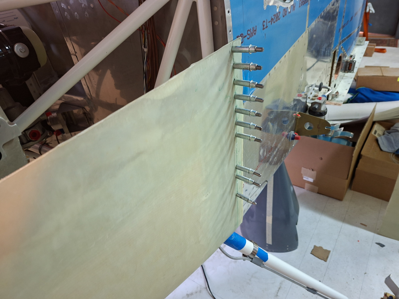
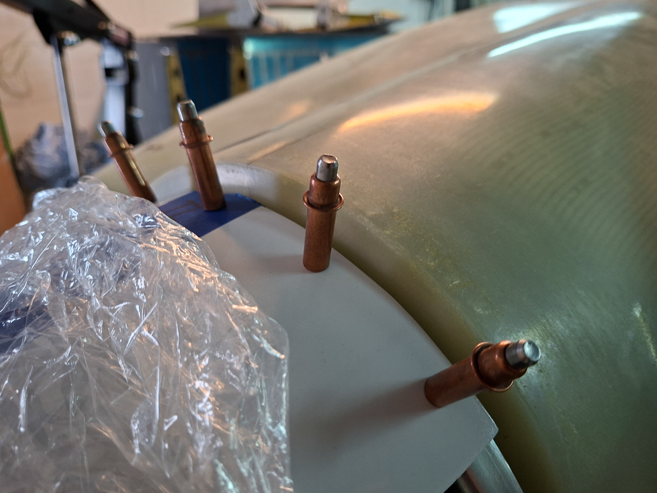
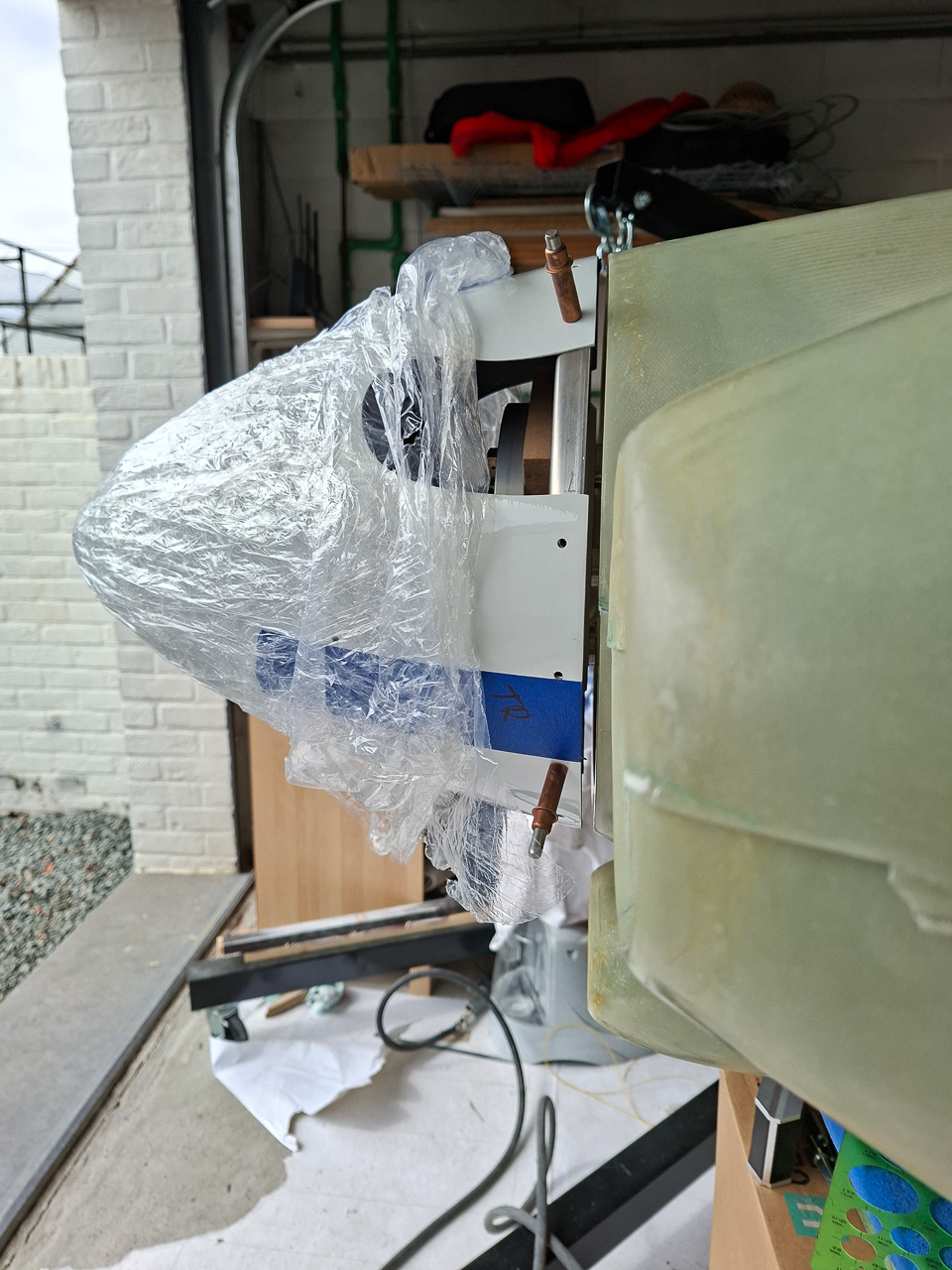
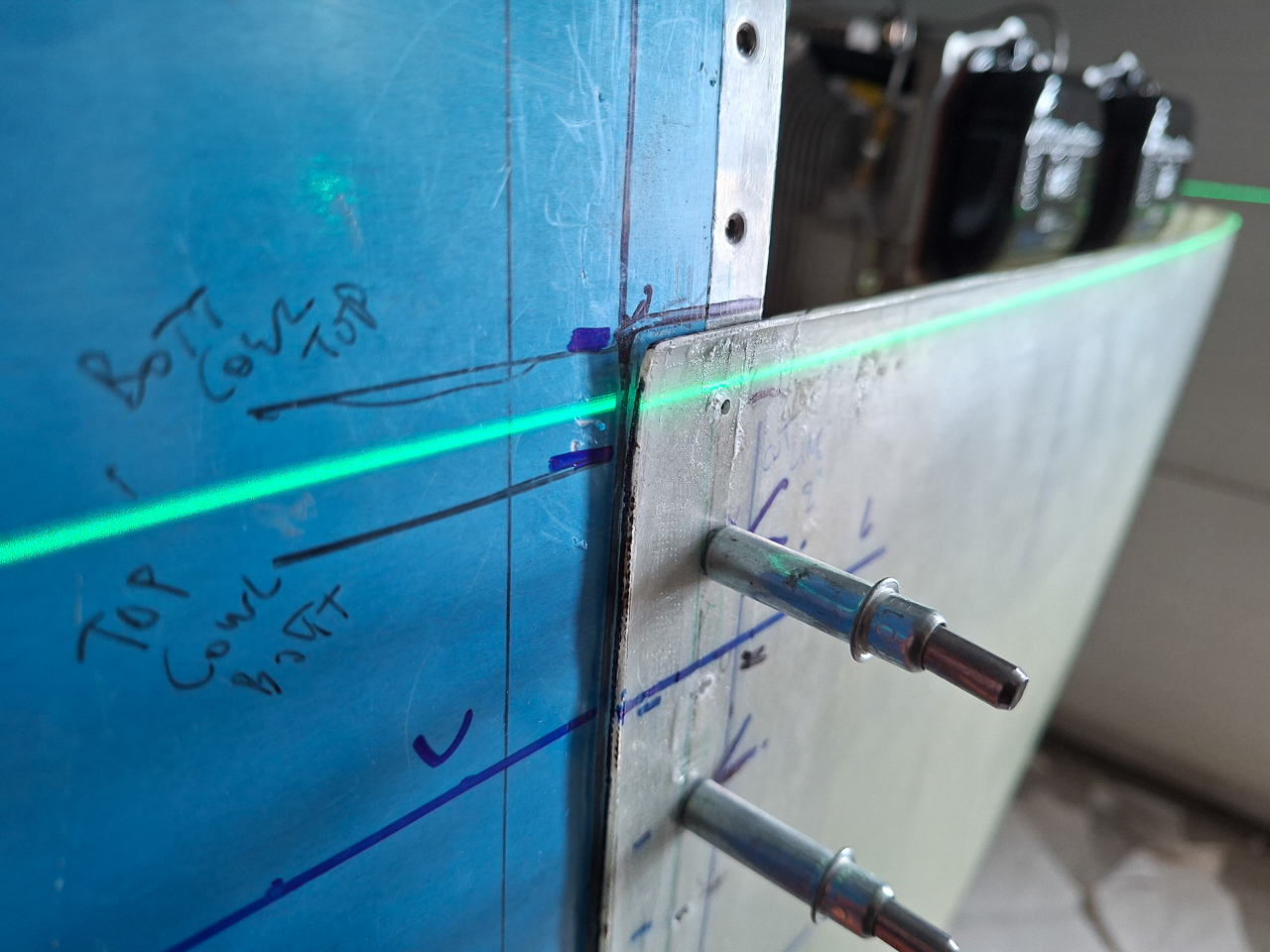
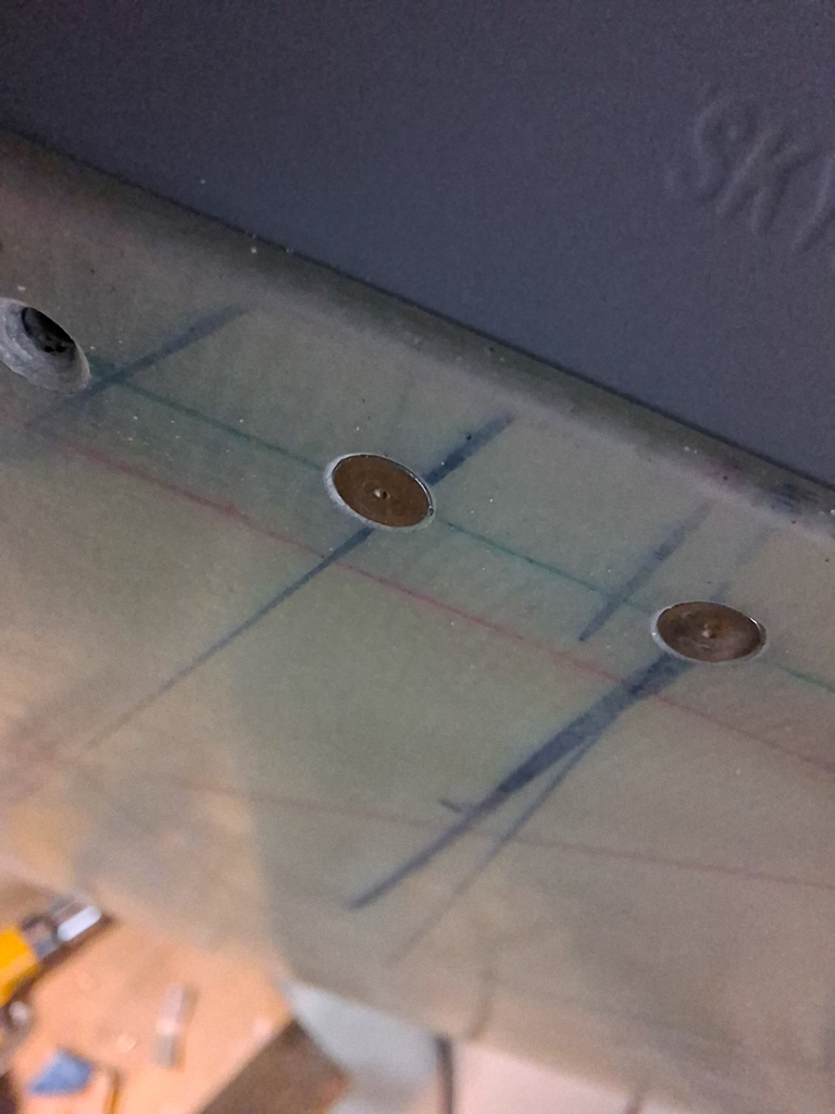
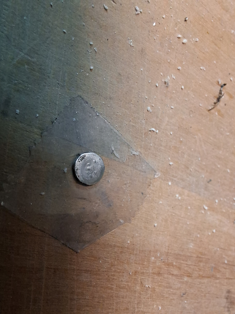
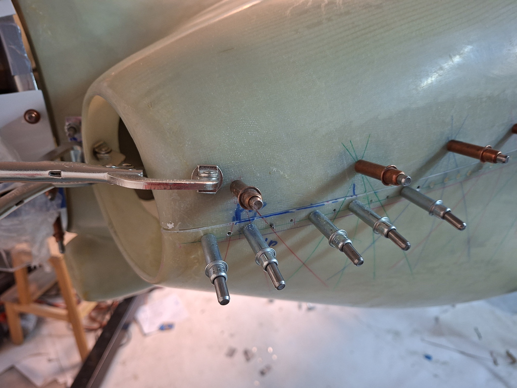
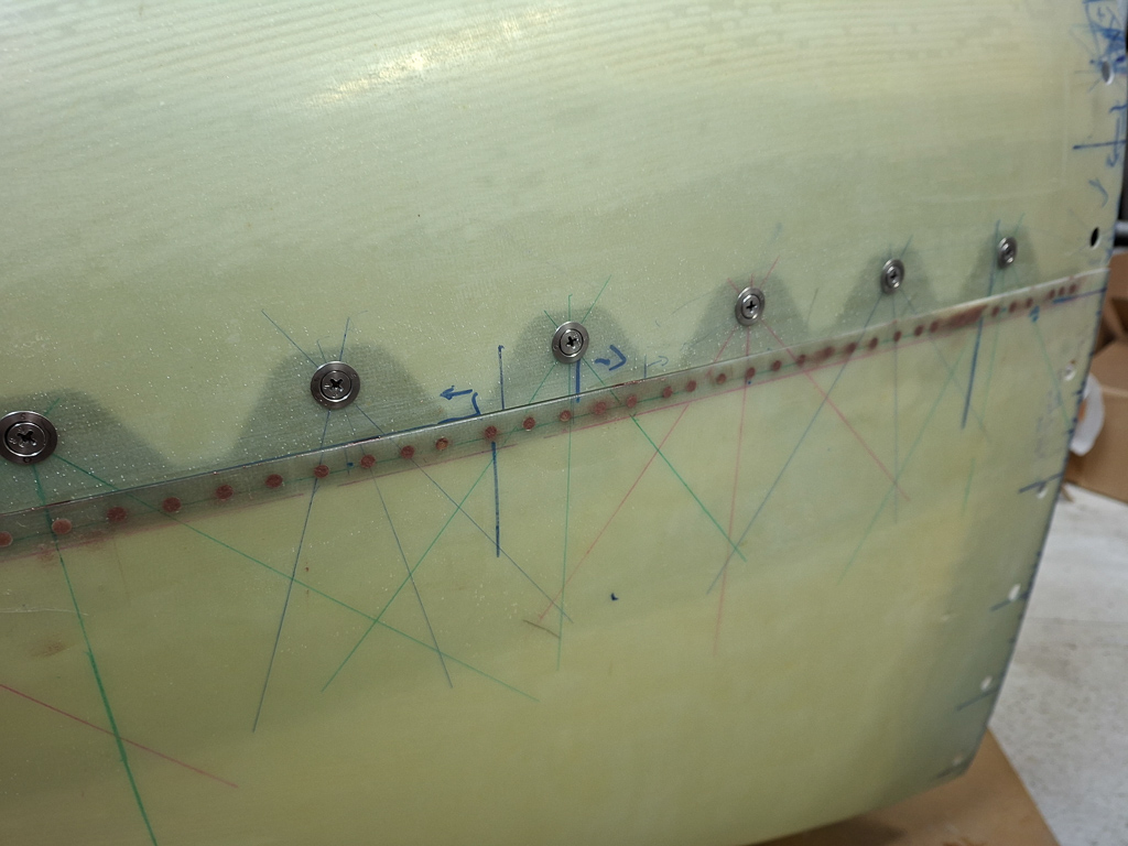
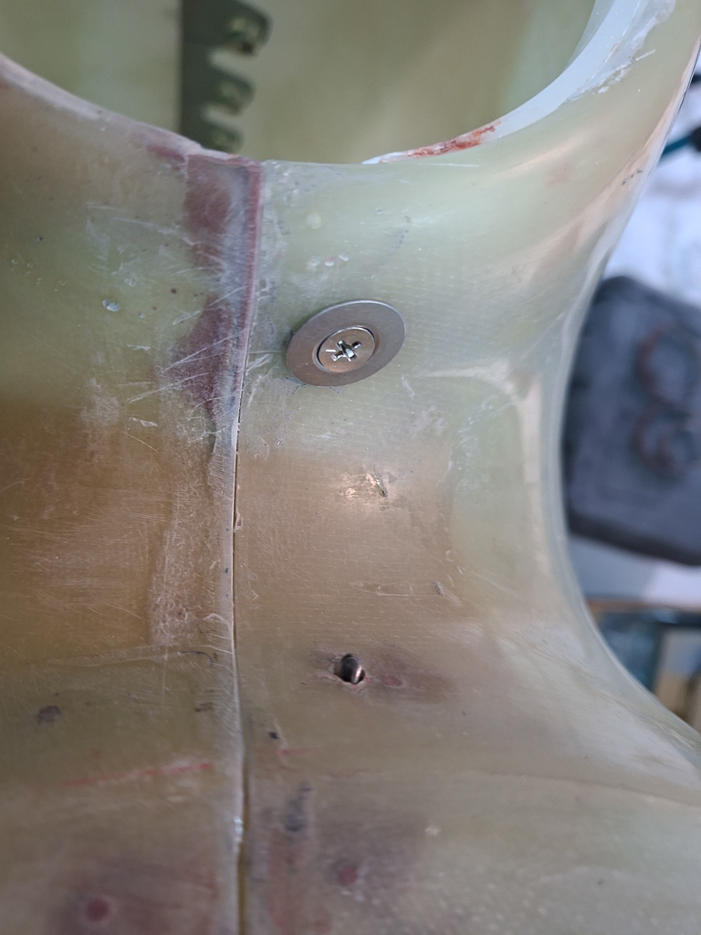
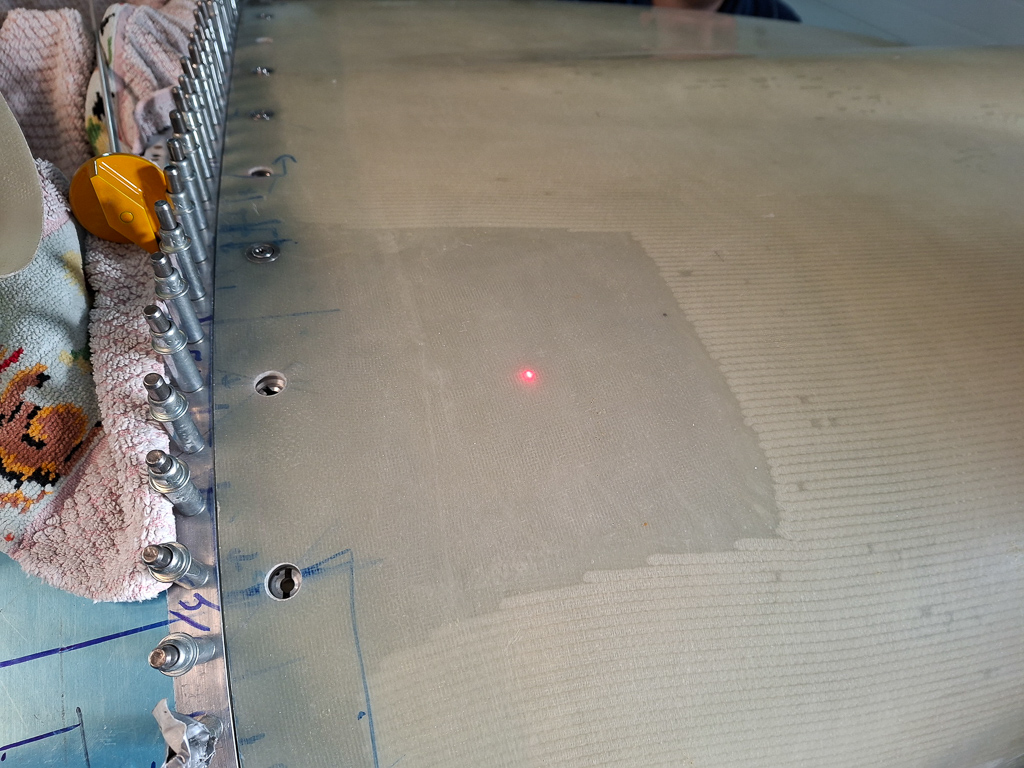
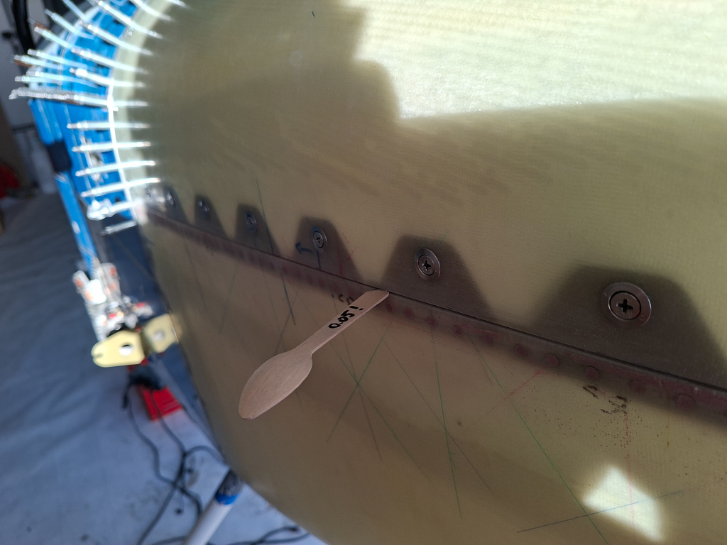
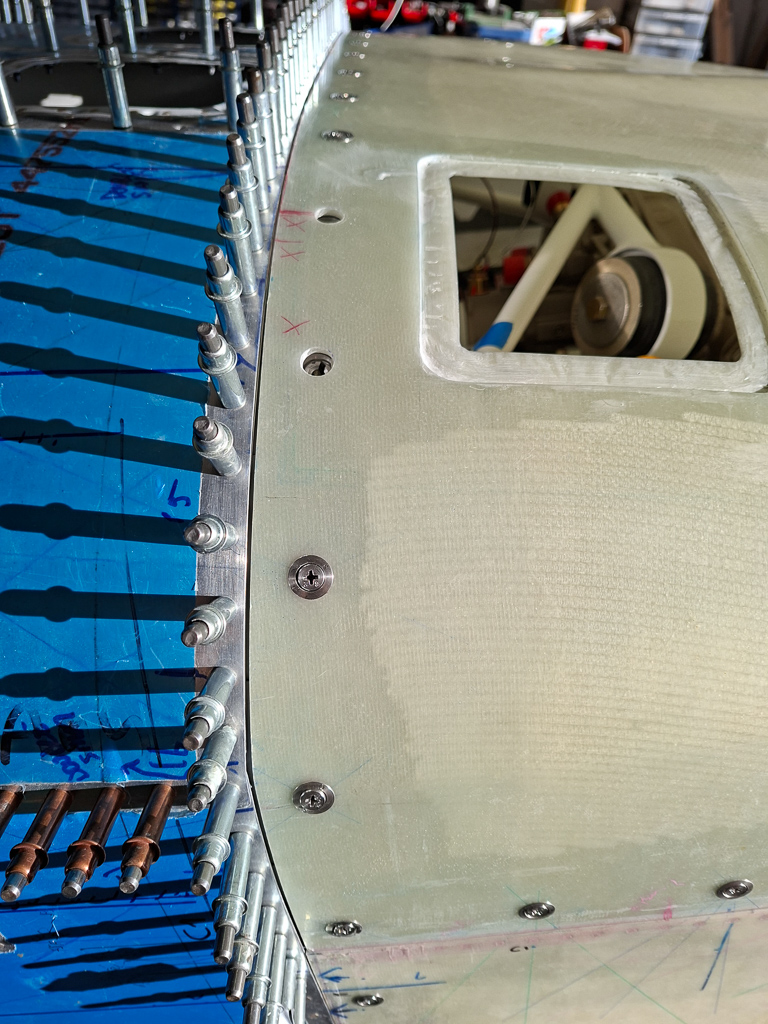
The fitting work has started. The big question to start with was: how can I assure the bottom cowl will remain in it's position once it's good, and how can I maintain that position each time I take the cowling on and off for cutting, sanding and fitting again. Making sure all sits well takes quite a bit of time and I don't want to be doing this same thing each time I take the cowl on and off. As the sides and bottom is still too long at this point, you can use this to your advantage and drill holes through the firewall rivet line on the front side of the firewall. drilling a small #40 hole here doesn't matter as you will be cutting this edge of anyway since you're passed the firewall edge. But it helps maintaining the position in place and placing it back to the exact same location as where you had it before.
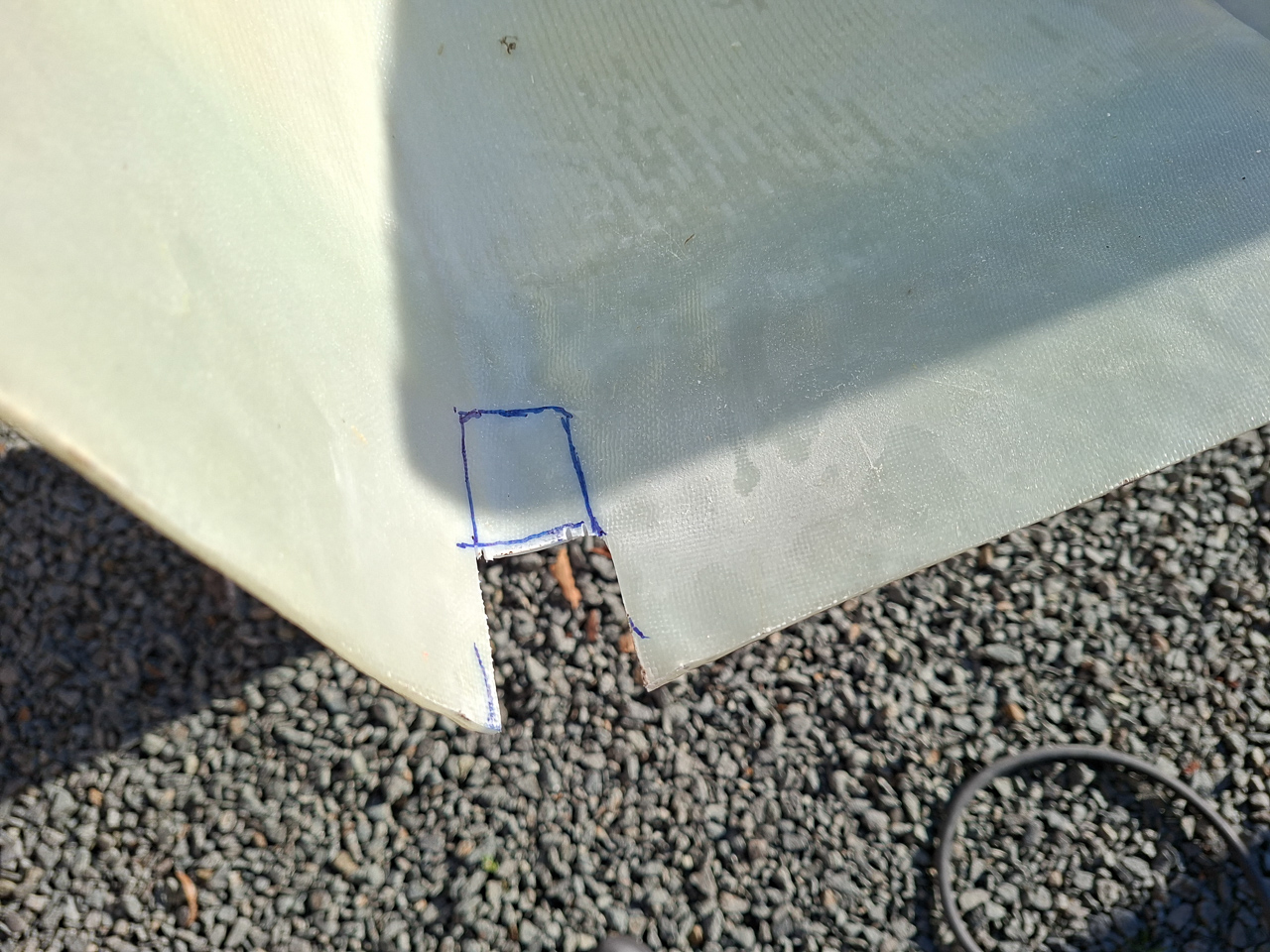
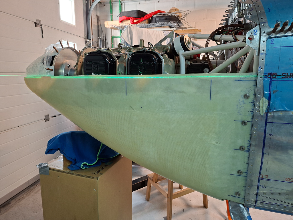
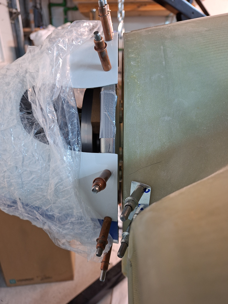
I started drilling holes in the sides in order to lock the position in place. Once these sides will be cut off, there may still be a slight movemement upwards due to the bottom cut and inwards due to the sides, but this will be a minor amount which you can account for now. as I had no idea at that point how much that move would actually be, I accounted for the thickness of the cowl and made sure my front distance of the bottom ring on the cowl around the spinner came just a tiny bit lower than the bottom of the actual spinner. as it will move a little up it will be a perfect transition in the end. This is quite theoretical thinking as in reality you still have some leeway to do minor adjustments when the side and bottom cuts are made. But it helps feeling good about the thought that you're in control here :)
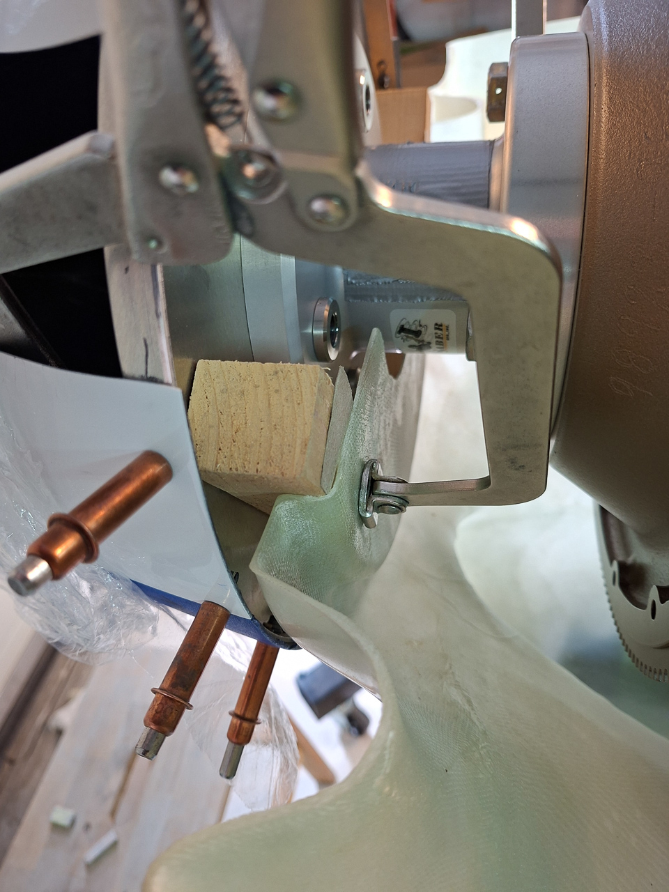
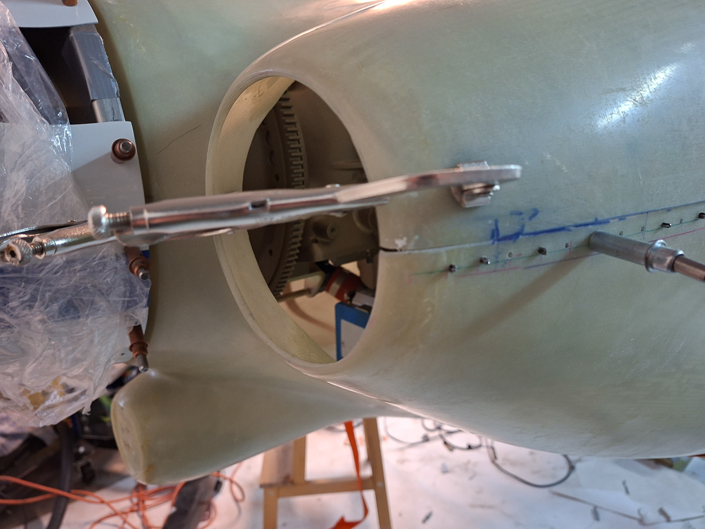
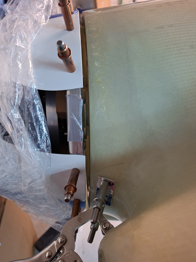
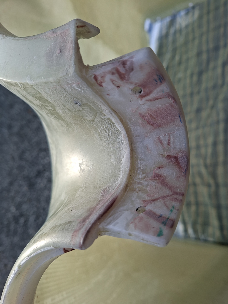
Another good tip to lock the front position into place is by using a wood block at the required distance between the back of the spinner ring and the ring on the bottom cowl. Some long vice clamps can reach over and into the spinner interior in the place where the prop blades will be. It's crucial that your wood block is the required thickness as this WILL define your final gap size between the cowl and spinner, which I wanted at 1/4 inch. Notice also the importance of not trimming out the spinner inner ring from the bottom cowl in the beginning. Just cut out enough to clear the saber extention but keep material around it. I would not have been able to use this method if the ring was cut out. Use the excess material to your advantage !
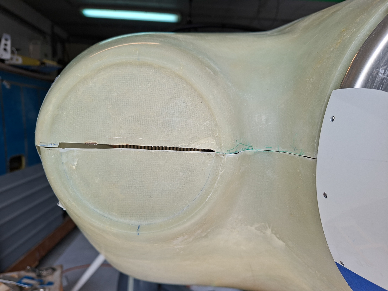
The space you see here between the cowl and the spinner is what it's all about.
A box and some wood blocks help to support the bottom cowl at the front. No rocket science but it helps support the front as you drill the first holes on the sides.
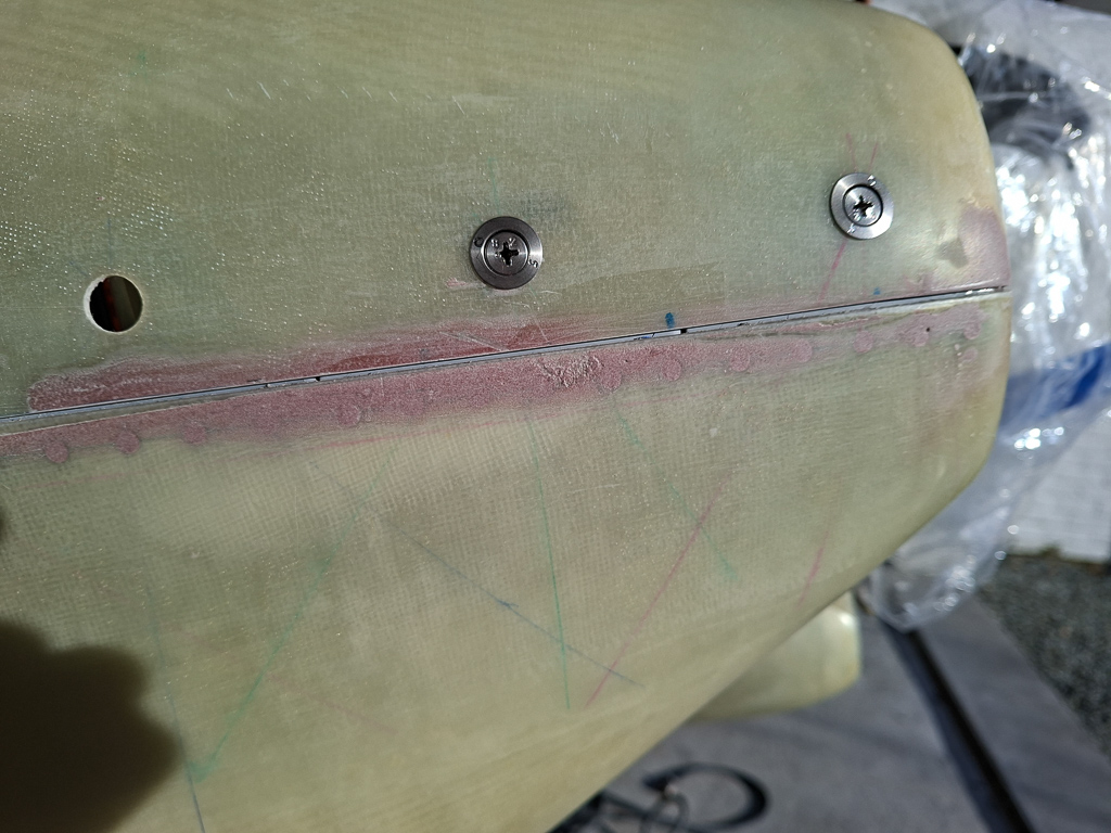
Then drilled all the holes in the bottom along the firewall line.
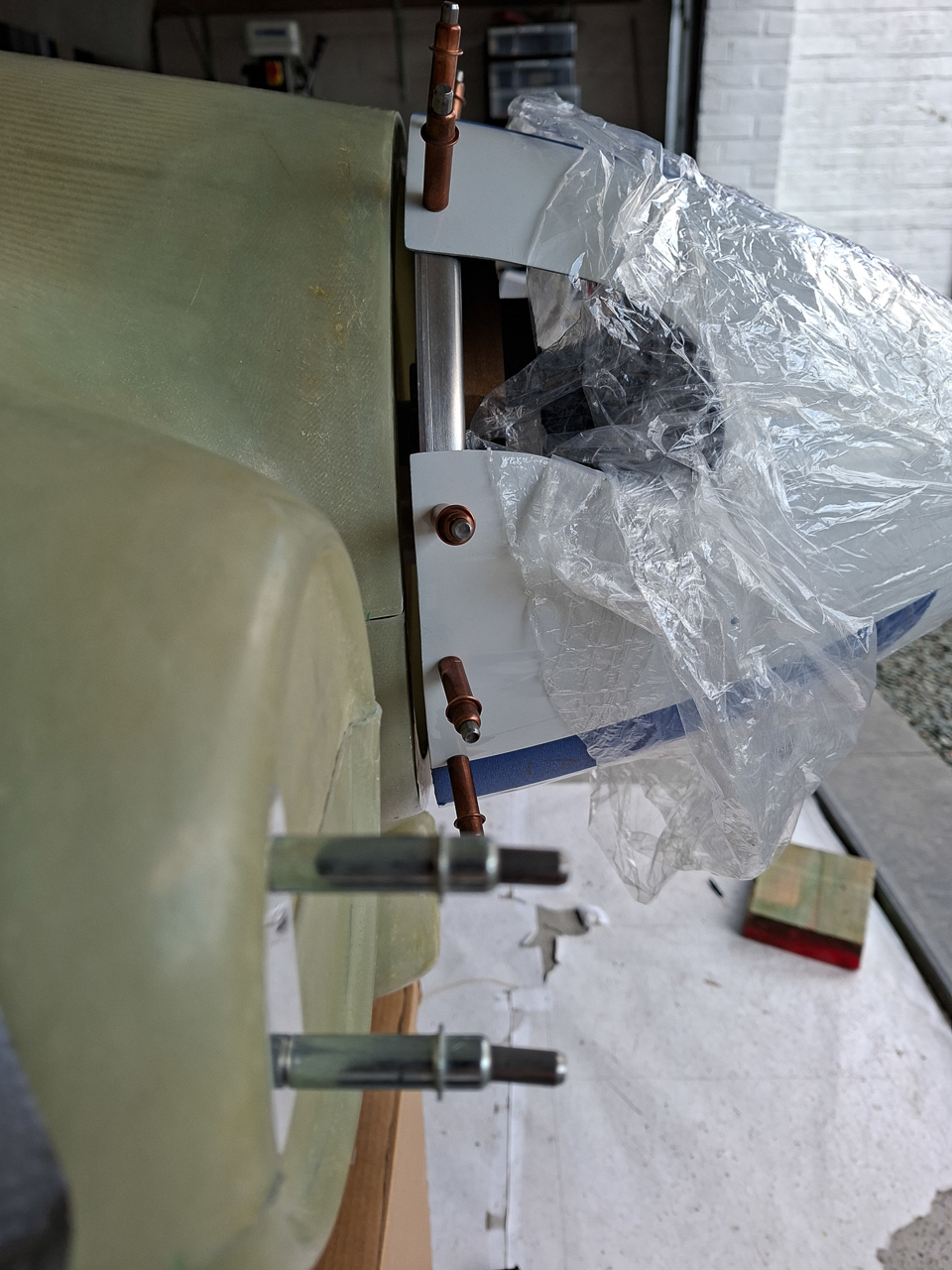
As the bottom is pulled on,the sides can be positioned and also drilled for #40 cleco's. Again, this is very temporarily as you will cut away those parts of the cowling but it helps getting the damned thing aligned as you cut the first lines and drill the first holes later on.
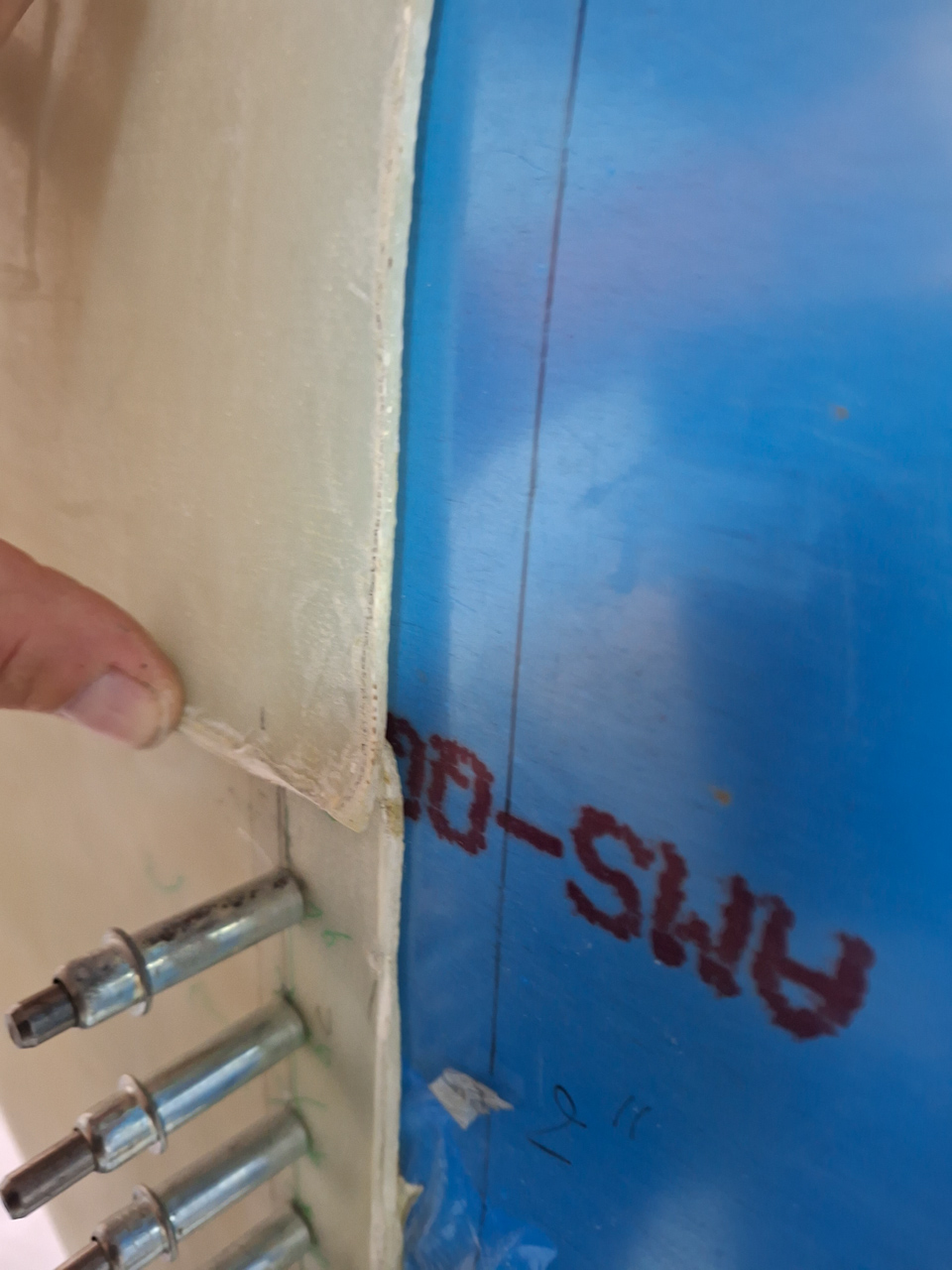
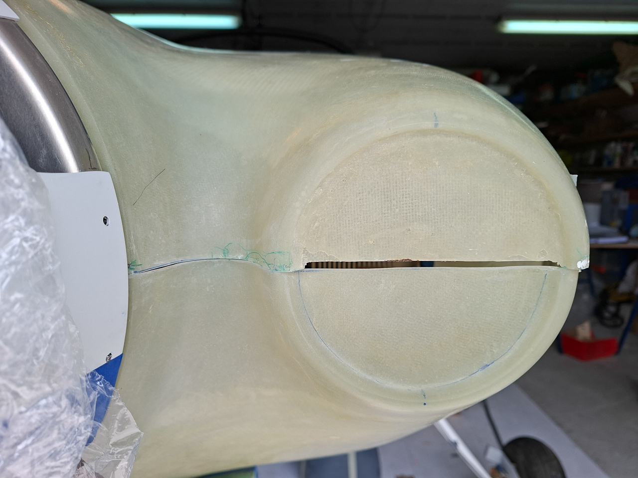
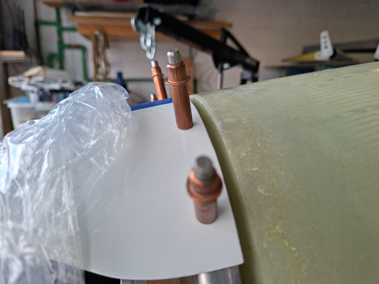
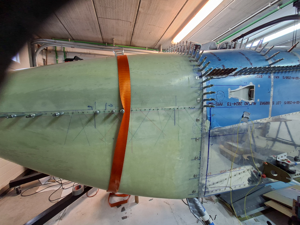
Here is a view from the side that illustrates what I just described. Use the front line of rivets on the firewall to your advantage.
The height of the sides of the cowl will be more or less equal on both sides. You can seee this on the image below where the top of the bottom cowling is pretty close to the same location as it is on the other side (image above)
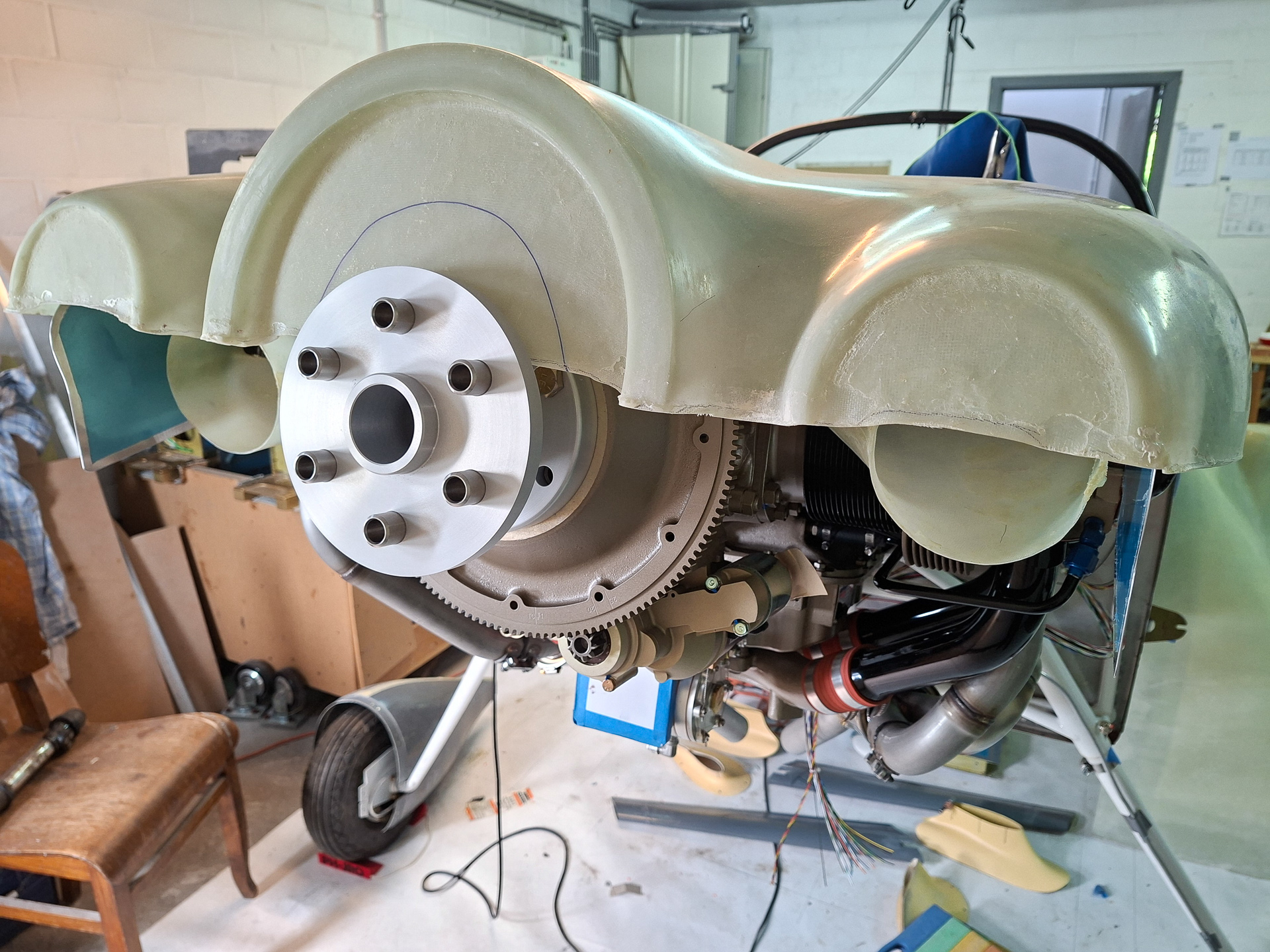
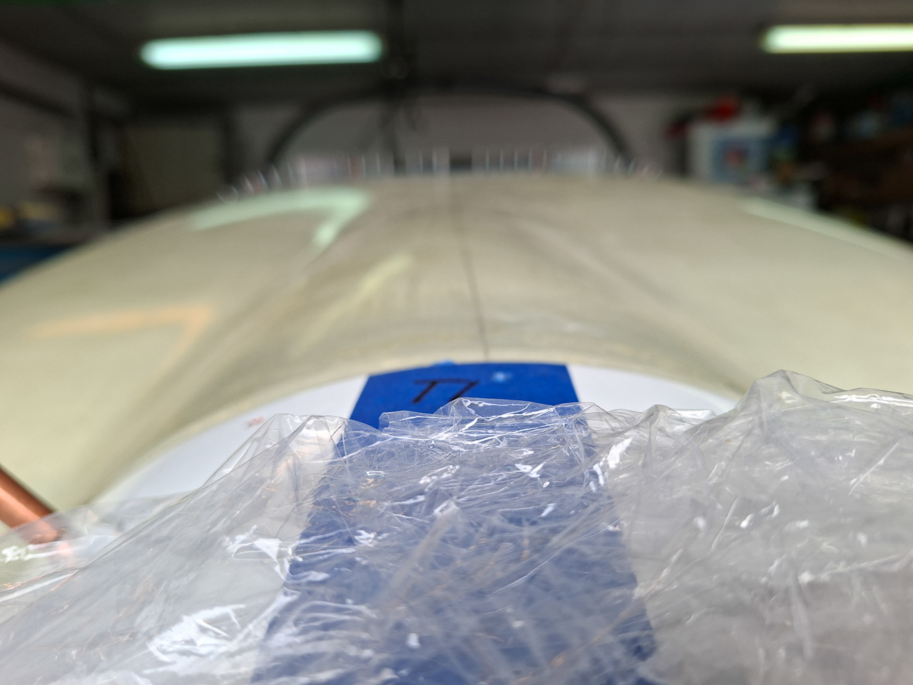
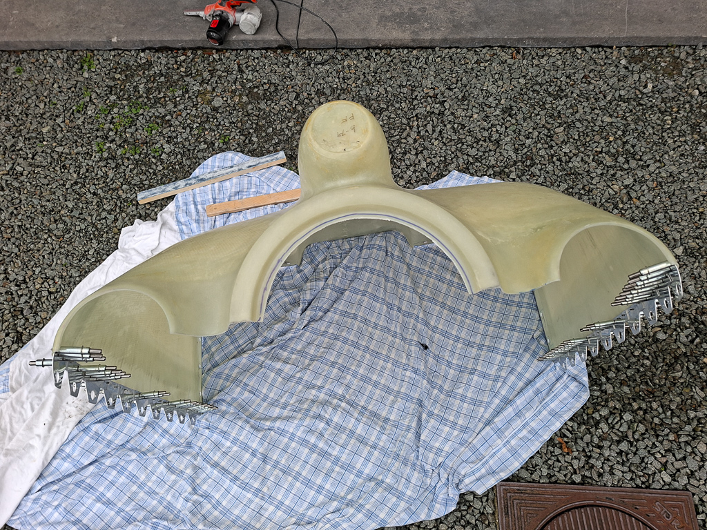
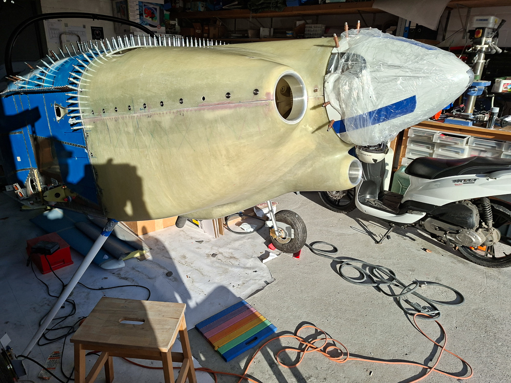
I took this wide angle shot from the front showing the top cowl positioned over the drilled bottom cowl. It looks pretty cool.
Little lower angle showing the 2 circular air intakes. Next step will be to sand and align the top and bottom cowl on that front line.
A view from the side. You clearly see the overlap on the sides. Don't cut anything on the sides at any point before your rear lines are cut and aligned with the firewall.
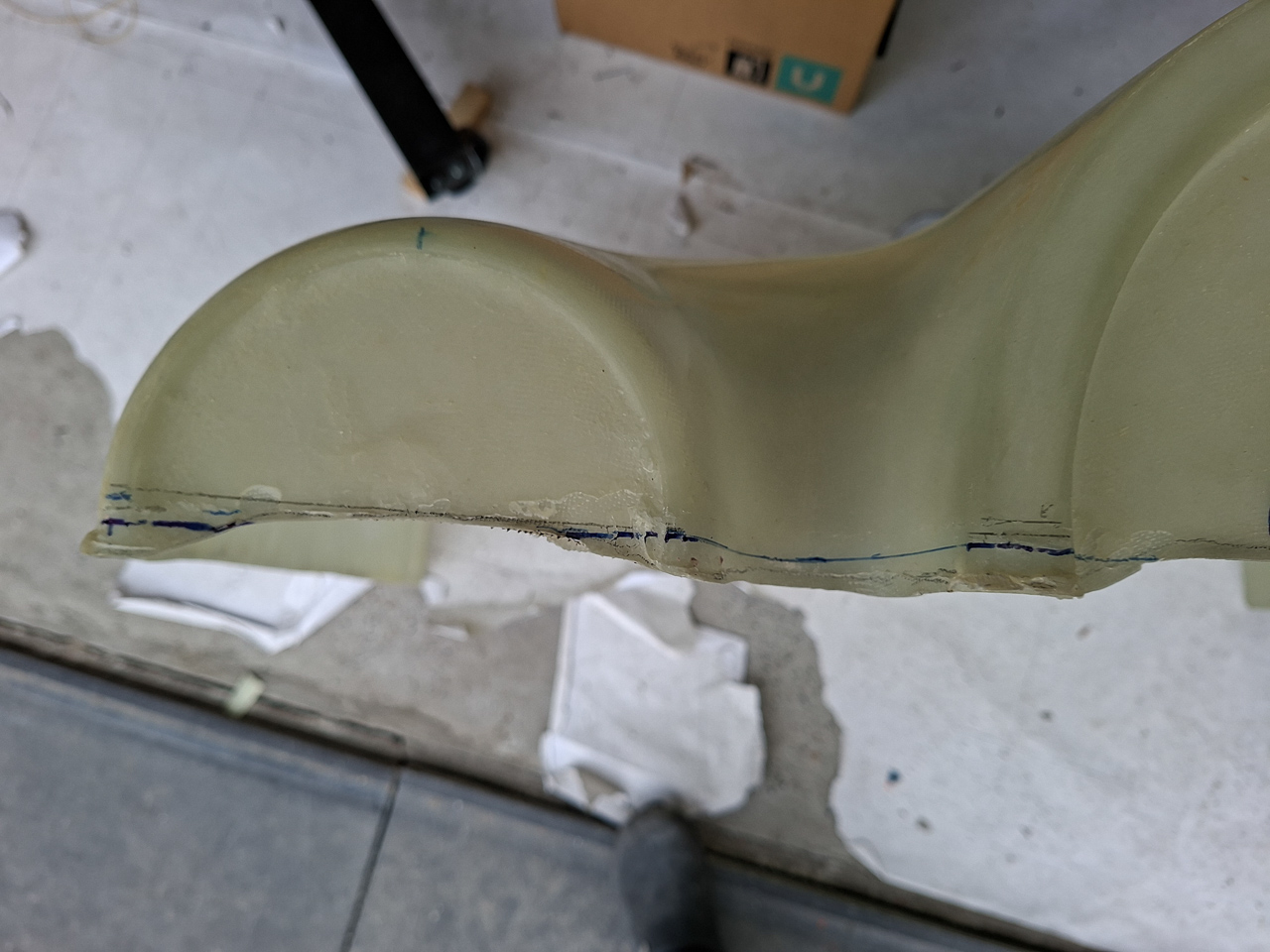
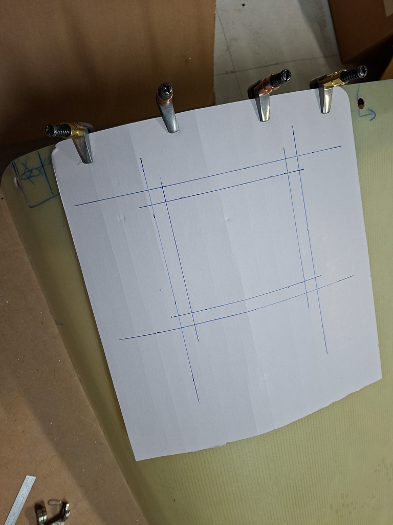
The overlap at the front is rough and not well defined. I will use the cardboard mockup of the intake rings and sand away material until I get a nice cirular opening and have the inner and outer front of the cowling in line.
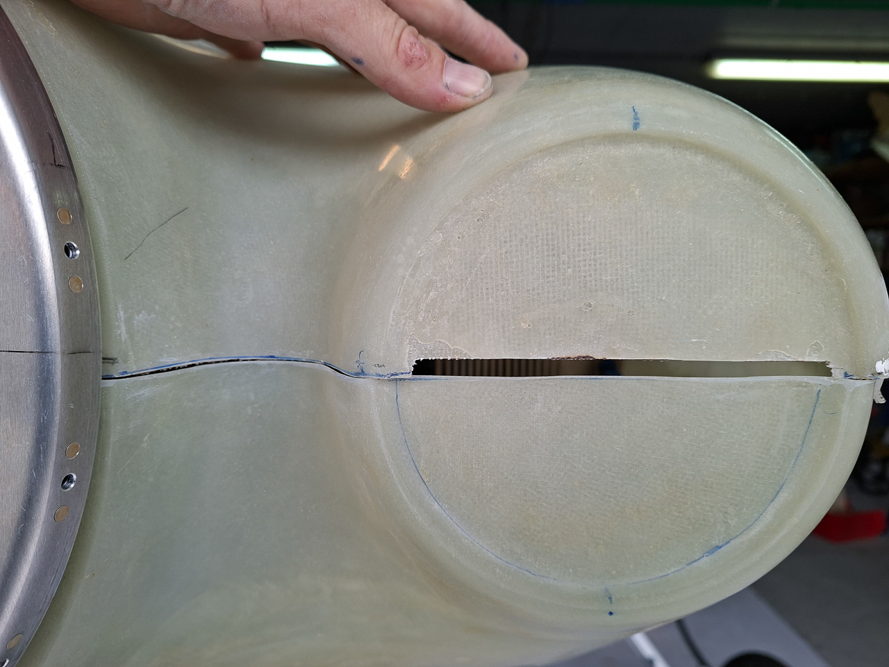
The top cowl lays still high at this point as you can see in the image below. That is because that front line is not defined yet and material will need to be removed to lower the top. The bottom cowl is already well aligned with the bottom of the spinner to get a smooth air flow over the spinner onto the cowl spinner part.
This is how much epoxy is in my overlap. Not much to work with so defining the horizontal split line on the sides will - in the end - be more or less defined by this overlap. The manual says you need a level line along the longerons as split line but measuring the front to middle of the overlap, the line looks like it will be slightly angled. Something only the master of the grand jury of the beauty contest will spot and honestly after 15 year in the build, I want to fly and not win kit prizes.
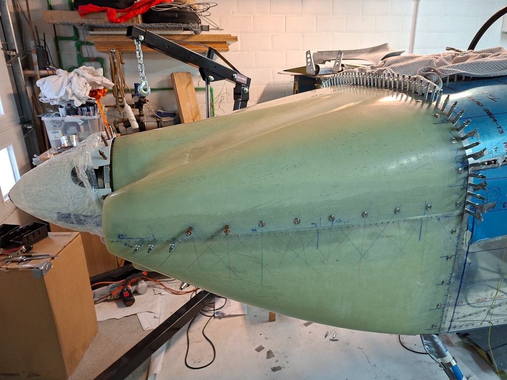
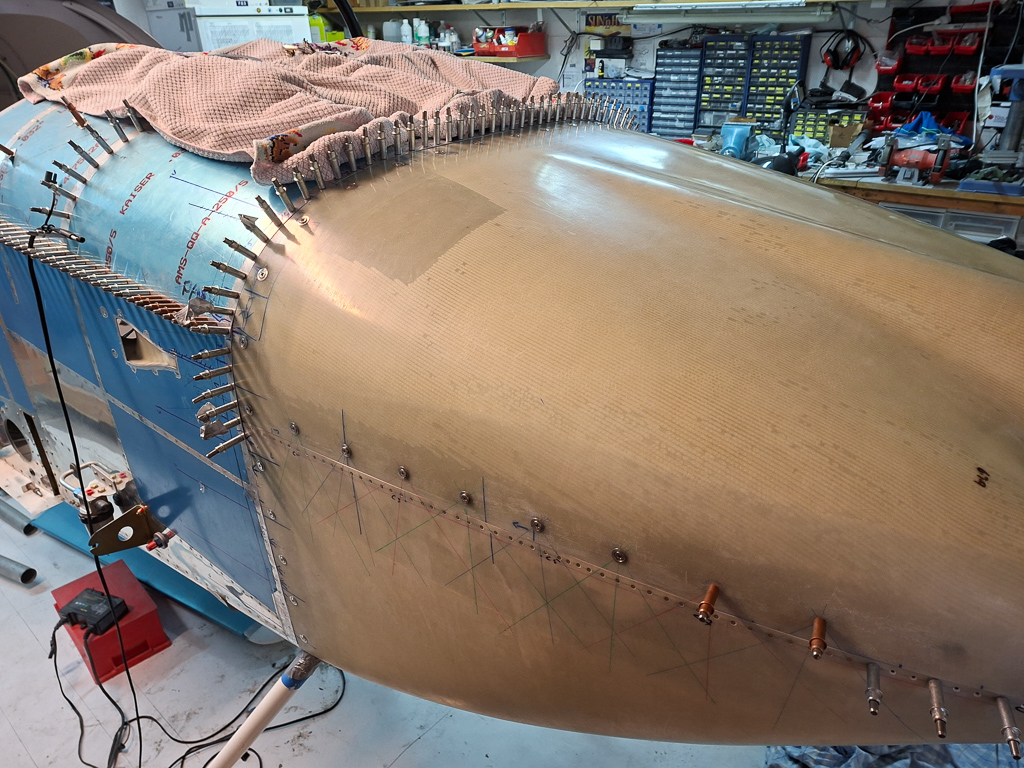
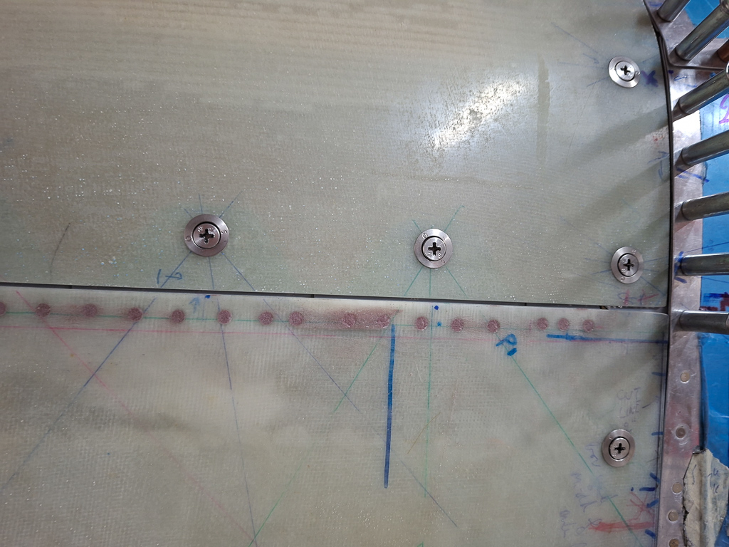
20/08/25 - Cowling (part 3) cutting forward line - 4h00
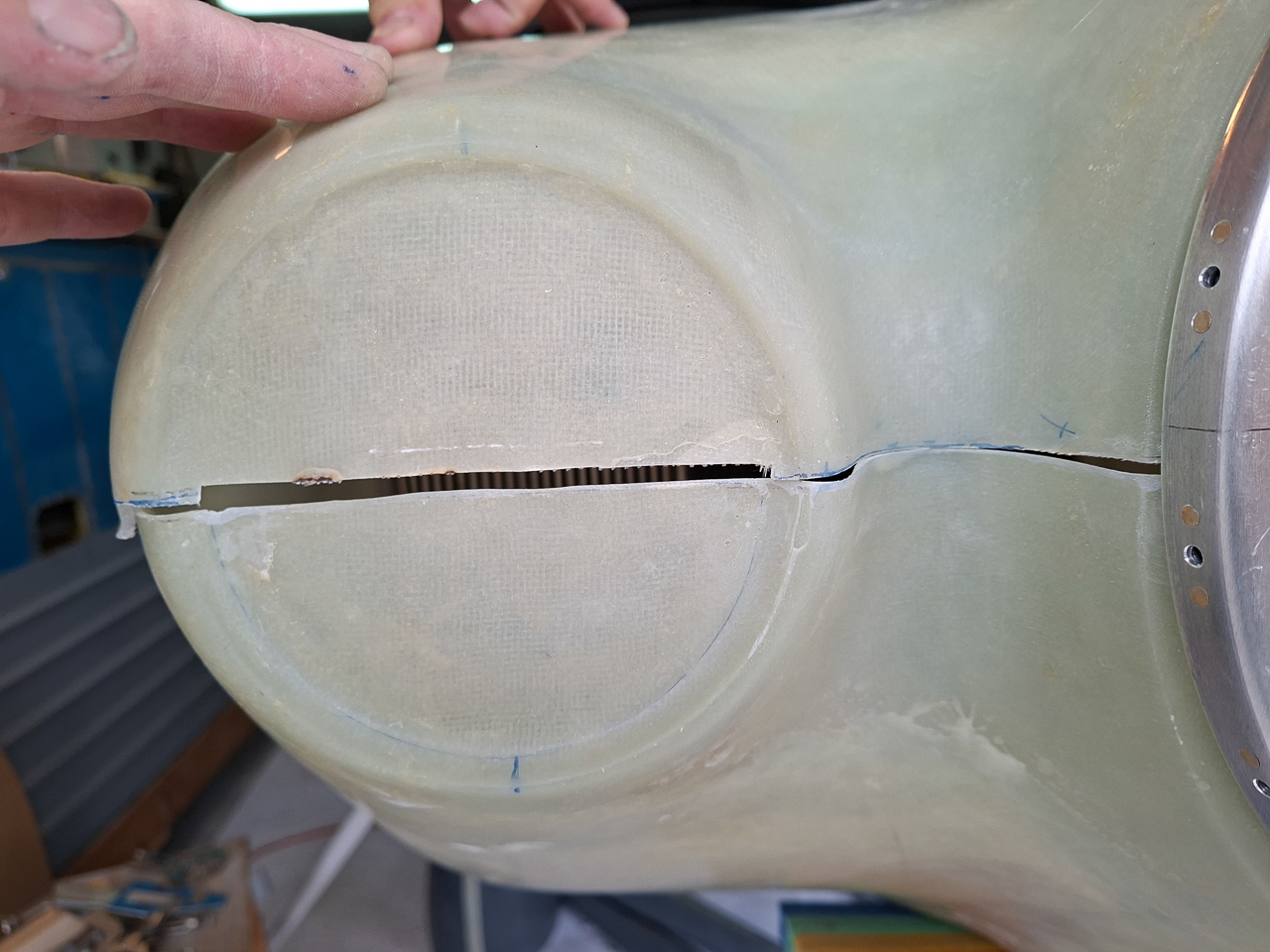
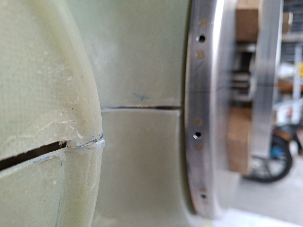
Today I worked on the forward line of the top and bottom cowling. This is a first step before you start cutting at the rear. The previous work sessions, I locked the position of the bottom cowling in place. Now I started sanding the bottom cowl line flat so that it is level. What I should also have done at this point is use a level, place it on the top of the spinner and measure the vertical distance between the elvel and the sides of the bottom cowl (the outer edges of the air intakes). This should be equal on both sides. I eyeballed it at this point but did this measuring later on and found that I was lucky. What I did to is use a straight sanding block and put the level on it in order to make sure the front line stays level horizontally.
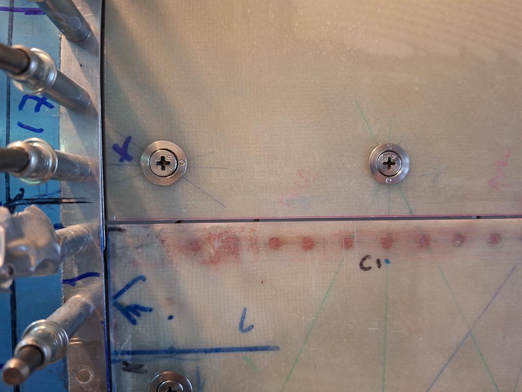
Other side I also got the 0 reading. One thing I haven't mentioned yet in previous articles : whatever you do, do NOT sand without using a long sanding block. It is almost impossible to keep a long line straight and level by sanding using only 2 fingers or the palm of your hand. Glue and stick the sanding paper to a long wood sanding block. That's the only way to make this work.
Here is the finish of the lower cowl split line.
Then I started matching the top onto it. I drew a cut line on it but stayed far away from it when doing the initial cuts. You don't have to remove much and it's quite difficult that make the line straight with all the compound curves at the front. A tricky process. Trust on your long sanding block to get the line straight.
After initial cut, I got closer to a fit but it was far from perfect. You can clearly see here that the rear part between air intake and the spinner still had too much material on it. I used the sanding block to take away material from both the top and bottom cowl in the rear cavity.
Some iterations later, closer but still not perfect
Much better already though compared to what you see in the first picture.
To make the fit clearer I needed to take away a bit of material in the void space between to top and lower air intake part. it really doesn't matter how that part fits as it will be cutout later anyway. I didn't want to be influenced by that so I cut out a small strip so the focus would lay on the middle and sides of the front cowl. (the black part of the image below is what I cut out)
Some iterations later I got to this point on the left and right side.
You can't call it perfect, but it's damned close to a straight line. I you get it this close, don't stress any further in trying to make it perfect. At this point you want to get very close to what it will become, but it ain't final yet. It's close enough though to start trimming the rear side. The top cowl aligns well now with the top of the spinner. It's almost equal to the height of the spinner.
At the bottom side, the spinner also sits flush with the bottom cowl.
So far... so good
You can see the relation of the top and bottom cowl to the spinner in the image below.
The spacing between the spinner and cowl lengthwise also still looks ok. The image doesn't really show it well but in reality the fit was ok.
Another day of fitting the cowl. As you probably noticed by now, I'm kind of obsessed on this cowl/spinner alignment before starting to make the first actual cut in the rear.
The transition looks good on the top. However I doubt how this has to be. I read about builders mentioning engine sag and having to take this into account. If the engine would sag a bit, that would lower the spinner in relation to the cowl. I'm really puzzled about this and whether I should place the spinner any higher than it is now. As a therapy, I went to the flight club where I fly now and had a look at the cowling of those 1970's cessna 152's.
I also read that you should use a ratchet strap to pull the cowl in near the firewall. Doing so, I did redrille some of the side holes as the sides moved a little higher. Don't put too much stress on the cowl or it will change shape as well.
used some sheet to protect the cowl at the top
In the end I started drawing arrows next to the holes that were the good ones... I think I'm over-doing this but better be more precise now than feeling sorry later on a 5K $ cowling.
Here's the other side. The two short black lines (below the piece of duct tape) represent the overlap.
I convinced myself this is what the final position will have to be. Drew the lines on from a reference line 2inch of the firewall forward line. Measured the 2 inch back on the cowl and connected the dots. This will be the cut line. As a backup, I used a thick sharpie pen to trace the edge of the sides of the firewall.
And did the same on the bottom.
I also made some horizontal lines as visual reference to see the cowl is at the spot it was before. At this point it was all still about leaving some visual clues so that the cowl could be placed back to the same location as where it was during the final fitting, once it had been removed.
At this point I'm ready for cutting. This will be the next work session
23/08/25 - Cowling (part 5) side line laser level - 2h00
I ended the last article saying I'm ready to cut...
not quite yet. I forgot that I also need to have an idea where the longitudinal horizontal split line would fall on the fuselage. This will be important in order to determine the place where to put the intersecting bracket that hold the CLock fasteners. The manual mentions that ideally, the CLoc would be in line with the side CLoc's that hold the top and bottom cowling together. No better way to measure a straight line on a non flat form than a laser level.
I made sure that the airplane was still perfectly level on the longerons and then positioned the laser level on a tripod so that the front of the laser line barely touched the front top line of the bottom cowling as illustrated in the image below.
On the rear side, I checked the position in relation the two marks I made defining the overlap while the top cowl was still on. The green laser line is not really in the middle of the overlap. Instead it's more towards the top. I do have to cut at least a little from top and bottom as the edges of the mold are rough. So the closer this line is in the middle, the better it will be.
In this image I also positioned the side bracket which should align with the horizontal front row of brackets. There will still be some leeway once the cut is made but I wanted to be close enough in order to determine the spacing and layout of all the other brackets.
I may decide later on to move a little below the green line to be in the middle of the overlap. This would create an angle that's only a couple of tenth's of a degree between front and rear. Again, this would probably disqualify it from winning the Grand Pize at Oshkosh, but I can live with that.
Before cutting, I came up with another idea of double checking the alignment of the spinner. I took out the laser level again did the same leveling as for the horizontal split line aligning the laser with the front forward tip.
I had drawn the middle line of the spinner back plate on both the spinner back plate and the forward crush plate. As I move the laser more forward, the green line projected on the spinner and crush plate as well. As you can see in the image below, the line aligns nicely with the middle of the spinner.
I still find it a bit strange that the level line moves down a bit towards the end. The longerons are level and the laser aligned with the front. Yet the line moves downward towards the back.
I marked the location on the side of fuselage. This line will be the top line of the lower cowling, so this is where the intersection flange brackets will be positioned on.
Did the same exercise on the passenger side.
Good alignment here is well
Marked the location of the green line on the passenger side as well. After removing the bottom cowling, I compared the location relative to a rivet near the point where the firewall bends foward. The measurement was nearly the same left and right. This also means the cowling is well aligned and in symmetry.
And then, finally I took it off and have it ready for cutting.
Another thing that needed to be completed before cutting was the positioning of the lower and side Skybolt attach plates. There are 3 fasteners left and 3 on the right side. The spacing between the center of the larger holes (where the Skybolt Locs will be placed) is about 3 1/2 inch. This is a guideline and you can play with the position as needed. The position of the firewall rivet holes sometimes falls right on the edge of a plate. You can not make them all aligned so that edge distance is achieved on all of them. In my opinion it's probably impossible to achieve that. If you really want that, you have to move the position of certain plates. That would mean that some fasteners will be more than 3 1/2 inch and some less. This would make it visually very unpleasing. I read multiple people mentioning the same story. Position them as good as you can and play with the spacing but keep the spacing equal. Below are my passenger side bottom brackets<.
These are the pilot side brackets. On both sides, verify that you can reach in to set the rivets near the landing gear leg.
The distance between the firewall eddge and the front of the bracket should be between 0.230 and 0.250. That is what the manual tells you to do. I would not do that if I were you, at least, I didn't. If you measure 0.230, the edge distance of the drilled holes is insufficient. It would be even worse if you use 0.250. I brought this down to 0.200 and that works well for having sufficient edge distance.
Cleco clamps work well here order to align the brackets and measure the offset distance.
You will need to cut away some flange edges where the bracket overlaps. Most of them need to be shortened on the unbent sides to lay nicely at the wiggle of the other bracket. On some of them you also need to cut from the top flange if a rivet hole is really on the edge of the bracket.
In the next image, I have drilled the 3 of the brackets on the firewall edge.
I did make additional hole when a hole was near the edge of a bracket. This will give extra strength.
You can see what I mean in the image below. on the overlap, on the right side of image, the hole is near the edge. So I drilled an additional hole in between the 2 existing ones.
Also drilled the passenger side. No need for additional holes here.
I bought this primer spray cans. They only had them in white and gray as primer and I think the gray will be visually ok near the silver colored firewall.
Finally I'm able to make the first cuts. And also finally I convinced myself that I can safely doing it without ruining a 5K cowling.
I first trimmed the bottom part of the cowling, left and right side. Your initial cut will have to be very conservative. Keep enough so you can do the fine tuning with sandpaper and a sanding block. The cleco's on the sides allowed me to reposition the cowling in the exact right location without having any more "grip" in the bottom. You have to trim the cowling line parallel to the bottom forward firewall skin. This is a precision task that requires some patience and about 5 to 10 times getting the cowling on and off. Using some ducttape helps but doesn't do miracles.
Each time I have to do a task like this I question the statement of Vans that an RV can be build by a single person. Getting the bottom cowling on and off requires a double pair of hands.
Below is a shot of the pilot side.
And a picture from the passenger side.
As you can see, no more grip down there so having the cleco's on the sides holding the bottom cowl from the fuselage sides is a real benefit to keep that perfect position. The cowl moves up a tiny bit (just a millimeter or 2) and you can account for that when drilling final the fastener holes. Most important now is to lock in that distance between the back of the spinner and the bottom of the spinner ring on the cowling. Not trimming enough here would mean the spacing in the front is too small. Getting this trim line too much forward means increasing that gap in the front. The first you can fix, the second is too late to fix. So be conservative on that first cut, you can always take away more but you can't put it back.
Here the final cut line is done. Well, for now. I try to cut as precise as possible with zero or very minor gap. When the cowling is fully done, I will sand away some more material to leave a 0.020" gap for painting thickness. Being precise now gives you the freedom to get it perfect in the end.
Next step I drilled #30 holes in the bottom cowl. Skybolt delivers some cleco adapters that fit in the large hole where the fastener will come.
This has a double advantage. 1, you can temporarily attach the cowl in the same spot each time without having to install the final fastener receptacle yet. 2, the cleco adapter works great as a drill bushing to get the starting hole perfectly centered in the large circle. Later on, you will need to enlarge that hole with a step drill and getting that pilot hole perfectly centered makes drilling the final large hole a lot easier without the need wander the step drill in the hole.
In the image below, 2 cleco's are installed
I did some measuring again to position the FSF-L and R brackets. These are the center line brackets on the firewall that should be inline with the brackets on the horizontal split line. The purpose of doing this is to be able to install the vertical brackets on the fuselage sides for the bottom cowling. If you know the positions of FSF-L, you can space the brackets below it accordingly to get a 3 1/2 inch spacing.
Below, the picture with the brackets positioned using 4 brackets below FSF-L. This is not my final layout but it gives you an idea what that would have looked like.
The bracket above FSF-L is a complicated one, it sits right in the bend of the firewall going forward at the top and you need to shape the bracket in order to lay flat in the bend.
As I have enough brackets, I decided to make the spacing a bit smaller and install 1 extra bracket. So finally I used 5 fasteners on the sides below the FSF -L bracket. I cut back the lower bracket and bent the tab inwards so it lays flat on the lower bend in the firewall. (the picture shows it before doing that)
This is my layout with 5 brackets clecoed on the firewall edge. These cleco clamps are real handy to move the brackets around while laying out and measuring.
To get an equal spacing, I used a small aluminium block between the tabs. As I mentioned in the previous article, don't use 0.23 to 0.25 as length of the tab exposed over the firewall edge. This is too much and you will end up with insufficient edge distance on the holes. I used 0.2 which is more than sufficient to do what it's supposed to do. The idea of having this part of the tab exposed is to avoid having "see throughs" at points where the cowling is trimmed a bit too much. Be precise and you won't need that. 0.2 is plenty.
In the picture below, the tabs are drilled to the fuselage. Make sure you install some clecos below the tab you are about to drill. This pulls the steel front firewall inline with the fuselage skin. If you don't do that, and they are not well aligned, you risk ruining the hole in the fuselage skin as the steel below is hard to drill through than the soft alumnium of the firewall skin. On the sides, most of them are aligned well but this will be important when you drill the top cowling holes near the top where the firewall steel sheet is flimsy and still moves
Before you drill, don't forget to cleanup that excess fuel tank sealant that was used to seal the firewall and fuselage side which may be sticking out at some points and prevents the brackets from laying flat against the firewall flange. At this point, I'm ready to trim the firewall sides on the bottom cowl. But as always with an airplane, there are 2 sides. First I have to complete the same thing on the passenger side.
I continued today on the layout of the tabs on the passenger side for the lower cowl based from FSF-R bracket. To be in symmetry, I used the same spacing with 5 brackets below FSF-R.
During drilling I wanted to make an additional rivet hole due to a hole being close to a bracket tab end.
I had a bad day... as you can see, the drill wandered on the steel plate and messed up the hole in the fuselage skin. Fortunatly no cracks or anything like that and it's an additional hole. I finally got through but the hole went to the left so also edge distance there will be crap. I'm just going to put a rivet in it and fortunatly the rive head covers the missdrilled hole.
A little higher up the row, I also made an additional rivet hole. This one went fine.
As I mentioned the bad hole is also moved inwards and is out of line. There goes my Grand Master Prize Champions title at Oshkosh.
Countersunk and deburred all backets and primed both pilot and passenger side brackets
Once dried, I placed them back where they will belong.
I had rivetted the bottom attach plates on but came to realize that the edge transition from cowling to fuselage was not smooth enough. A shim would be needed to make the step from the bracket to the fuselage skin larger. Unfortunatly this also meant drilling out all the rivets I had previously set.
Before drilling out the rivets, I decided to drill the remaining holes in the bottom cowling using the cleco adapters as a drill guide. You can see the cleco adapters with cleco's installed in the picture below.
I also started trimming the cowling at the lower fuselage sides. It takes a lot of iterations having the cowl on and off before you get this perfect. In the image below, the edges were trimmed and I installed 2 #30 cleco"s in the cleco adapters.
It looks quite cool to have the lower cowl finally on in it's final position.
The gap in the front looks very good and is approximalty 0.25". Right were I wanted it to be.
Another picture.
You can still fine tune the edge a bit using a long sanding block. Don't try to sand locally by hand, it will ruin your straight line. I had to trim an additional bit towards the top of the lower cowl. This moved the whole cowl slightly. You don't have to take away much material to get a significant result in the front. If the gap is too large, you can always fill it up later but be precise. Mine butts against the fuselage and will need to be sanded down a bit more to allow for the 0.02" paint gap. The more precise now, the more playroom there will be to sand the final gap. I'm pretty happy with what I have now.
Spacing spinner cowl from passenger side.
Then I trimmed the other side of the fuselage and used the same procedure.
On the inside you can see the cowling hanging from the 2 top cleco adapters. Have someone supporting the bottom as you drill these 2 holes to ensure the cowl fits snug against the brackets.
The I worked on making shims of 0.032" aluminum. I realised now why these long strips in the finishing kit were supplied but unfortunatly I used them already on the elevator and rudder fairings. Damn... cutting long straight lines ain't easy. I then installed the shim behind the fuselage edge, held them in place with cleco clamps and drill all holes.
All holes drilled #40, the shim is now ready for deburring and dimpling.
When all 4 were ready, I used the spray can to put primer on them.
23/09/25 - Rivetting flanges to firewall - 3h
Short work session. The primer on the flanges has dried and I installed them with the shims underneath on the bottom and side firewall flanges. For most of them I used the pneumatic squeeze to set them.
Here is a picture of the pilot side bottom cowl side flanges rivetted on.
I had previously rivetted the bottom flanges but drilled them out and made shims to be installed underneath. Some of these were shot with the rivet gun and bucking bar.
At one place, I had to install an oops rivet, my rivetting skills are getting rusty after long time not doing it.
In some places, the space for placing a bucking bar is really thight like here around the weldment of the engine mount. I have a small triangular tungstend bucking bar which is just perfect for this kind of locations. It is small but still has sufficient mass in it to set rivets.
27/09/25 - flanges, assembling skyloc fasteners and installation of bottom cowl - 3h
An exciting day working on the bottom cowling. Finally got to the point that I can install the skybolt CLoc receptacles and hand the cowling by it's skybolt fasteners.
First I had to rivet the receptacles on the Skybolt flanges. As mentioned in the manual, make sure the locking pins are easily accessible. On the sides, orient them so that the locking pins are in the top, in the bottom ones (as in the image) , I oriented them to the inside. The locking mechanisms are the small black plastic pins you can see in the image on the edge of the receptacle. As long as the pin is inside, you can turn the fastener in or outwards making it sit deeper inside the cowl. You need to turn them so that the screw is flush with the aluminum grommets. Once flush, you can lock the position by removing the pin, then with a screwdriver turning the inner mechanism in the receptacle to the 1:00/7:00 position and you will see/hear the locking clip locking the insert. I will wait with this step until all fasteners are in and the cowl is fully in place.
You can still adjust the depth later but it requires inserting a metal pin (pick tool) in the same location to unlock the locking feature but it's a hassle and I prefer to do all of them at once. I used the pneumatic squeezer to set all the AD4 rivets.
Previously , I had all the holes drilled in the lower cowling to #30 by using the cleco retainers delivered with the Skybolt kit. These things are worth gold and I wish they even would have supplied some more of them. With the cowl installed with all the cleco fasteners, I removed one fastener at a time and traced a line with a sharpie pen around the inner opening where the receptacle has to come. This gives you the perfect reference where the grommet and fastener have to come through the cowling. The bonus is that the drilled #30 hole is already perfectly centered so this makes the updrilling much easier. I did one by one, each time removing, tracing and replacing the cleco fastener so that the position of the cowl stays well in place.
Then took out the #1 unibit step drill and enlarged the hole to 15/32". This is actually easier than I expected. The center hole is already well in the middle and I didn't have to "walk' the unibit much to keep centered within the traced circle. The unibit in epoxy allows you to move the hole to the center up to the last step. In my case, as my center hole was already good I didn't have to correct much and ended up with a hole like in the image below.
And now for the frustrating part of the day... You get the grommet (top) and the retainer (bottom). You have to insert the retainer inside the grommet and at some point I was convinced it is impossible. The manual makes a reference to the 4P3 Pliers tool and I regretted not having bought it. The grommets are concave in the bottom, the studs will insert till about 3/4 of the way and then hit the embossed bottom part of the grommet. I'm new to skybolts and I couldn't picture how the studs work. It is very simple, the studs don't move and there is no gap or special place in the grommet that allow the stud to slip in. But there is a trick which is easy and it took me some hours to figure it out.
You don't need the pliers tool. it work as easily in a vise, a screwdriver, wrench and drill. More about this, some images below.
This shows my problem in detail. Looks like there is no way to get this in.
Meanwhile I did some more rivetting with Matthias on the bottom flanges.
And installed the remaining receptacles
And now for the trick.
The way I got the studs into the grommt was to place the grommet in a vise and lightly press it. Not much, you don't want to deform it. The vise is just there to hold the grommet in place and have both hands free to manoeuver the stud.
I used a wrench that just fits over the stud and supported it by a drill on the vise. Make sure the stud is inserted with the bottom legs in line with the vise. The idea here is to be able to tilt the stud while applying vertical pressure with a phillips screwdriver from the top. Press on the screwdriver as you tilt and move the wrench to find that magic spot where the stud slips through the grommet. It does work, be patient.
Et voila... the impossible is possible.
There are also some locking rings. I decided not to install these yet as it will be difficult to remove them again when the grommets have to be removed for painting. It's not clear to me yet what they do exactly but I guess they just lock the grommet in place on the epoxy from the inside, preventing them to drop out
First one installed...
And also the other bottom cowl skybolts got installed. This looks really nice.
Continued on the side walls. Drilled some more 15/32" holes in the epoxy and installed the remaining grommets and studs, each time fitting the cowling the ensure the fit remained snug. I am very satistfied with the way this turned out so far.
03/10/25 - Completed hanging bottom cowl with Skylocs - 3h
Continued and finalised the installation of the Skybolt fasteners on the bottom cowling. It is now fully hanging by the grommets and retainers in the Skybolt CLoc kit. Below are some more detailed images.
Passenger side vertical line. All locking pins in the recepticals are oriented up.
Bottom corner passenger side. The cutout for the legs are a bit large and I will close these down with some epoxy later on.
This is the same side view from the outside. The fit is good. There is a small gap on the top inch but it's due to the cowl being unsupported and hanging by it's weight, pulling the cowl forward a bit. I think this will not happen anymore when the top cowl will be installed and stiffen up the entire cowl structure.
You can see the gap better in the image below. I can push the cowl back a bit from the front and then it closes up again. I'm not too worried about this now. The entire cowl back line will have to be sanded a bit more in the end to allow for the 0.02 paint gauge gap.
The alignment is good. Not perfect but more than good enough for my quality standards. I may sand the edge down a bit where the cowl is still a small bit wider than the fuselage. I would be more concerned if the fuselage would be wider. In my case there's a very minor step from the cowl to the fuselage. I could make an even thicker shim between cowl and fuselage but i prefer not to go thicker than 0.032 sheet for the shim.
Same image on the pilot side.
Same remark on this side. Cowl is very slightly wider than the fuselage but nothing to worry about. The Grand Prize Jury will definitely notice this but it's the least of my worries right now. After 16 years, you just want the damned thing to fly and not win beauty contests.
View of the pilot side showing bottom and side of the bottom cowling.
The cowl is hanging by itself now and the gap around the spinner is still in the place I wanted it to be. Good result for now, this is a good basis for starting mating of the top cowling..
Same view from the other side
04/10/25 - marking top cowling + positioning top flanges - 2h
Work on the cowling continues. The next step after hanging the bottom cowl is positioning and cutting the top cowling.
I made an initial marking on the back of the top cowl by positioning the top cowl over the bottom cowl and aligning top and bottom cowl at the front line around the spinner. Then went back to the firewall and measured back 2 inch from an offset line that had drawn before on the top fuselage skin, 2 inch backwards from the firewall edge. This gives me a first indication of the cut line.
But then I realised that first I would need to position and install the Skybolt flanges around the top of the firewall.
It took me an hour to get an initial spacing that was satisfactory and would leave some leeway at the FSF-L and FSF-R flanges near the cowl split line.
I am using cleco clamps to hold them in place. This works quite well.
One flange is on the center line, the others are spaced equally (3.4inch) until passed the bend. From there on they are a bit closer to eachother but overall I like this spacing. There 's enough room for the receptacles near the engine mount bolts and the FSF flanges still have some playing room in case the split line will still move a bit.
19/10/25 - drill skybolt flanges to top firewall - 5h
The skybolt flanges on the top of the firewall are final positioned. The offset of 0.2 from the edge equal for all flanges. I drew some lines on the middle of the flange extending on the fuselage skin so that I can remove and place them back in the same position.
Many of the flanges need slight bending and near the engine mount significant bending. I did this by hand using a vise and a wood block. You can make a nice curve this way in lack of large and expensive equipment.
One of the challenges is that you need to drill through the flange but the top fuselage skin is not yet rivetted on the firewall plate. They tend to be moving out of alignment. If you would only clamp the flanges with no clecoes to keep the skin together, you risk enlarging the hole of the top fuselage skin (the drill will go through the top fuselage skin and find the harder steel plate underneath and pulls the drill to the side causing an enlarged hole in your fuselage skin). To prevent this, I removed the flanges left and right of the one I'm about to drill and installed clecoes in the skin so that the holes are better aligned prior to drilling. This is shown in the image below. The flange shown here is the top center flange. Notice also that my top flange is installed on the centerline of the fuselage.
Same idea viewing from the top
As the first ones are drilled, moving down to the sides, each time removing one extra flange towards the bottom and repositioning the one removed previously. It requires a lot of remeasuring but the technique works well.
As mentioned above, some flanges need some bending on them to follow the curvature of the top fuselage skin. Placing it in a vise, clamping and applying gentle pressure using a wood block makes this easy. Move it up 1/4" inch in the vise and push some more. Doing this over the entire length will create an even curve.
Moving along one by one.
The flange at the bending point of the fuselage needs some special attention. There is an 8 degree tilt above the longerons. To make sure you have sufficient edge distance at the rear side of the flanges, it's required to cut the back side of the flange at the point where the fuselage bends. Illustrated in the image below by the red line in the bottom
All flanges drilled.
I also positioned FSF-L and -R but didn't drill those yet. I want to decide on the horizontal cut line later on during the top cowling cutting process.
At this point, I'm ready to cut back the top fuselage. The clecoes create an additional difficulty for fitting the top cowling : I am not able to rivet the flanges on. Rivetting the flanges on means installing the full top fuselage skin and I can't do that yet as I still have a lot of electrical wiring to do. In the end, I clecoed most of the clecoes from the other side where I could. That way, I can at least lay the top cowling on the edge again and remeasure my cut line. Once the initial cut is made and I'm getting closer to the edge, I can place the clecoes on top again.
I realized I forgot one important detail before starting cutting of the top cowling. I still needed to create some 0.032 shims underneath the flanges to lower the flanges in order to get a good transition with the fuselage top skin. So had to take them all off again and make some long strips of aluminum stock along the entire length of the firewall flange. I made multiple sections, the image below shows the top center section drilled in place. I remember Vans delivered some long strips of aluminum cut to width and I always wondered what they were used for. In the end I cut them up and used them as shims under the empenage fairing. I hate myself for that now as now I have to make long straight strips by hand. That takes time... Fortunatly I still had the canopy rear skirts in aluminum which I have not used as I have fabricated my own skirt in epoxy and this was 0.032 sheet. They are rather long so make up as perfect stock for cutting up into long shims.
Then moved down left and right. Clamped it on and drilled.
Then reinstalled all flanges to get the extra depth to accommodate for the cowling thickness. As you see, I numbered the flanges and wrote the corresponding number on the fuselage skin. I also countersunk and cleaned all edges on all top fuselage flanges. A short sentence describing what in reality took a half day work.
Then I repositioned the cowl, double checked cut line measurements and used the plexi cutting disc delivered with the canopy to cut a straight line near (but not on) the marked line). Be conservative at this point. It's hard to picture the final position during the first measurements so be carefull cutting to close. What's gone is gone and it's ugly to have a wide gap between cowl and skin.
Cut off complete.
Repositioned the cowl and tried to match the location around the spinner. This will always be your reference point for positioning. Everything else still can be re-adjusted at this point but the front around the spinner has to match quite accuratly.
What makes this very difficult is the overlap on the sides near the front of the cowling (where the duct tape is in the image). It prevents you to lay the cowling down nicely and pulling it over de-forms the bottom cowl a bit. It's too early to cut the sides at this point so I will have to do it with this for now. What I want to do at this point is getting the spacing of the front of the top cowl in line with the distance from the spinner. I used a piece of thick aluminum angle for this as it represented the spacing I wanted to achieve (it's the material used to make is AA6-187x2x2 which is the left over of stock used to make F-601J angle on the firewall. This thickness is a nice spacing distance between cowl and spinner.
Then the process of sanding down started. It takes a zillion times positioning the cowling, marking and sanding a bit more.
I used a narrow hand beld sander. It works really well if you have the right skill and technique to sand straight lines. I used 80 up to 180 grit sanding paper belts on low speed to smoothly walk over the edge and bring the line down forward. Make sure you also have some sandpaper glued to a long straight woodblock so you can often check if your line is still straight.
After some cutting back on the rear line, I'm getting so close to the edge that it becomes important to be very precise. My issue at this point is that the horizontal sides are still too long on the top cowling and overlap the bottom cowl. This squeezes and deforms the bottom cowl a bit causing some shift in shape which makes me wonder if the line I'm making on the firewall will remain accurate once the sides will be cut. So I made the decision that I will start cutting the horizontal sides close to where they need to be and then re-evaluate the back at the firewall.
In order to do so, I decided on the final height of the bottom cowling horizontal line and sanded it flat. Next step was to draw a line where the rivets would come for the flanges attached to the bottom cowl horizontal line. I used a flexible tape measure to draw a line.
Then verified it with the laser level. As you can notice, mu bottom cowl side line is not perfectly level with the airplane but it's not noticable so I kept it as is.
Clamped 2 flangs on the horizontal sides and exposed the tabs by 0.20". With these 2 in place, I used the steel rules to extend the centerlines on the side of the fuselage skin. This defines the center of the FSF-L flange receptacle. With that defined, I drilled the FSF-L in place. Next step will be aligning the rest of the flanges on the horizontal line and drill them to the bottom cowl.
01/11/25 - installing side skybolt plates on both sides of cowling (measure, make to size, drill) - 7h
Earlier I had finalized the horizontal side line of the bottom cowl and committed to this height.
Today I drilled the pilot side flanges on the horizontal split line of the bottom cowling. I played a bit with the spacing and found that 3.4" gave me a good spacing measuring from the firewall FSF-L flange forward to the front of the cowling. I wanted to make sure that the spacing was equal along the line and that the last receptacle would be pretty close to the front near the air inlet. The prescribed 3.5" in the manual places the last one too close. Shortening to 3.4" means you have to shorten the tabs a bit on the non curved side.
The cleco-clamps are really useful again in this when repositioning. I drew the locations on the top line with a ruler and marked the epoxy every 3.4", then positioned the middle line through the center of the flange on this mark. The red line in the image is the bottom of the flange if it extends 0.2 passed the edge, the green sharpie line is where I will drill the holes through the plexi in order to have sufficient edge distance on the flanges for AD3 rivets. I don't have a rivet fan and this is one of those places where it would have been really handy. Had to measure all rivet positions with a ruler and pulled som black marks over my green drill line. These rivets will be countersunk deeper so that a layer of epoxy will cover them, so you will never see them but force wise, it 's better to have equal spacing between the rivets anyway.
Drilled the first ones and put clecos in place. I will probably not need any shims here as the top and bottom cowl have equal thickness.
All flanges drilled. The last couple of flanges need some light bending to fit to the curvature of the front of the cowl. Later on I will also need to bend them inwards a bit to allow the top cowl to lay nicely against the flange.
The offset of 0.2" allows hiding small gaps between upper and lower cowl. At the last flange before the FSF-L flange at the firewall, the last flange does not cover the entire length up to FSF-L so I made an additional small shim to place underneath the last flange closing that gap.
This image illustrates the curvature of the front of the bottom cowl. The flanges also bend outwards a bit so up to halfway, they will gradually have to be bent inwards. Lightly in the middle of the cowl , increasing towards the front.
I had some time left and started doing the same operation on the passenger side, drawing the lines.
Using the flexible ruller
transferring the line
And measuring back for the minimum edge distance on the flanges
02/11/25 - Cntd skybolt fitting and drilling. Cutting 2 air inlets. More fitting top cowling - 4h
Continued work on drilling the passenger side flanges.
Used the steel ruler do determine FSF-R position and mark a line on the firewall skin. This is than the reference line to position the center of FSF-R flange.
Here FSF-R is added and drilled in place.
The gap between the first flange on the side and FSF-R is a bit more difficult to cover here. You need a longer piece simulating the joggled bend in the flanges to cover the back of the last flange on the sides.
I managed to make a bend that works well.
Clamped it in place and drilled.
Passenger side fully drilled.
With the time left, I started marking and cutting out the air inlet holes from the top cowling. I placed the rings directly on the cowl and traced the edge.
Then I started cutting close to this line and using a dremel with sanding disc curved it nicely round. Each time checking the fit of the air intake ring. sanding a bit more and trying again.
This is as far as I will go for now. I might go a bit wider but I first want to cut the bottom cowl side as well and verify the global fit.
The reason I'm doing this now is because I want to get a better idea of how good my initial cut on the front of the top cowl was and if I need to cut a bit more there. I can only do that if I know both halves fit nicely around the intake ring. The reason I want to know the front is because I also want to start cutting back the bottom of the top cowling side line in order to get a closer fit without overlapping. This will give me a less distorted bottom cowl and hopefully allows me to cut back precisely on the top cowling at the firewall top line.
05/11/25 - cutting out 2 air inlets from bottom cowl - 2h
Short work session, continued cutting out air inlets on top cowling. Both are now trimmed to size.
Positioned the rings to verify the fit. Might need a little more trimming but I prefer to be conservative for now until the bottom cowl is also cut.
passenger side
pilot side
06/11/25 - Fine tuning top cowl fitting - 3h30
Getting into the final steps of trimming the top cowling. I have been trimming back on the horizontal split line on the top cowling to get the horizontal line closer to the final position. By doing this I got rid of the annoying overlap that distorts the bottom cowl when fitting. It's still about 1/16" too long but it allow butting the two halves together nicely now and work accuratly on the rear line at the firewall. I was unsure if this was a good idea to cut already the horizontal line as in the manual they say to do this only after the rear line is done but I'm really satisfied and happy I did it this way.
With the sides aligned close to the final position, this is what I see on the rear line at the firewall. There is still some more material to be removed. I'm using a blue thick sharpie pen to mark the places where I need to trim down the line. Most of it was in the bends on the sides, the top was getting pretty close.
For now I don't bother about the vertical side underneath the bend in the firewall. Once the top falls in place, the cowl will move down another 16th of an inch and that angle may still change so you don't want to cut this side yet. First do the middle top and work your way to the sides.
Here you see that once the cowl came down and fitted on the flanges, the horizontal line has to be trimmed down again. I marked a blue line and took of another millimeter.
By doing so, the front starts also to get more in alignment and I was also checking each time if the ring still fits nicely in the open air inlet.
Key is to place the cowling at the distance from the spinner which is equal on all sides and has sufficient room so that the spinner cannot touch the cowl. A too big gap is also not good as it will be visually unappealing. I used the stock angle between the spinner and cowl to ensure the ideal distance. You can see the stock angle sticking between the parts in the image below. Also make sure that the cowl is supported from the bottom to get the top cowl front aligned vertically with the spinner. In my case, the weight of the top cowl is moving the bottom cowling down a bit creating a too big step between spinner and top cowl. I put a wood block under the bottom cowl scoop to support it. I hope that when I drill the holes for the fasteners in this way and attach top to bottom along the firewall line and sides, the cowling will become stiff and the whole thing will support itself and remain in the positions I defined here without any sag. Hard to know now, but I'll see that when we get to that point.
Same view from the passenger side. There is a very small difference between the distance between pilot and passenger side but it's really minor.
More trimming on the passenger side. The curved sides are good now so I marked them as 'no more touching', the top still needs some more trimming. I'm using the hand belt sander with 120grit paper on low speed to take away more material. On slow speed, you don't take away much material and you can be very acurate. I'm always using my long wood sandblock after using the hand belt sander to ensure the line remains straight. As the top line and side line is now pretty well defined, and the top cowl lays on the flanges, I can also trim down the rear vertical sides below the firewall bend line.
I'm getting very close to drilling the first fastener holes on the top cowl. It took a lot of patience and placing the cowl a hundred times on and off the plane to fit but I'm close to a good fit and it was worth the effort so far.
09/11/25 - drilled top line of top cowling to fuselage flanges. - 4h
Finally a feel good day again in the shop. After many days of trimming and sanding, I was able to fixate the top cowling top line to the firewall.
I started the day with more trimming and fitting. following my classic technique of marking with a sharpie pen and sanding it down. The edge in the bend came out ok and I also trimmed down the vertical line. This gap is still too tight for painting but I'm planning to remove the extra 0.020" for painting only at the last moment. I prefer things to be snug for now so that I just have to sand down a little more without the risk of creating oversized gaps.
With the side line also at final size, I was able to use a clamp to fixate the position of the upper and lower cowling at the air inlet side. The stock angle defines the gap at the spinner as shown in the image below. I'm less worried about the fit in the center transition. This can be adjusted and worked on later on. There will be an epoxy layer added behind the bottom cowl which will hold a nutplate that ties the top and bottom together with a screw.
Also clamped the passenger side
Rechecked the fit on the passenger side. looking good.
The top line sits snug and lays flat on the flanges with little or no gap. All lights on green to start drilling the first holes.
The next problem is that you have no idea where to drill... as the top cowling lays on top of the bottom, there is no way you can trace a hole or make markings. The only solution I came up with was to install the cleco adapter in the flange and draw intersecting reference lines on the fuselage which all center in the center of the hole of the cleco adapter as shown in image below. 2 lines is sufficient but I want to be precise and made 4 lines to increase the precision.
Then I used duct-tape to tape the cleco adapters in the holes of the flanges. That's the only way you can keep them in place while drilling blindly through the top cowl.
And below you see the result. Lines extended back from the fuselage reference lines and drilled first #45, #40 and then #30.
An easy and precise technique that worked really well. All holes were dead center and as you can see by my line between cowl and fuselage skin: it's still dead on.
I started drilling on the center line of the airplane and move down alternating left and right, each time pressing down on the cowl while drilling so that the cowl fits snug with the fuselage skin.
Another hole drilled
Time was up for the day but I'm very pleased with the result, I made it up to the fuselage bending at the sides. Next time I will drill all the way down and evaluate the horizontal trim line again before also drilling those holes using the same technique. Unfortunately, there are not enough cleco adapters in the kit to do all the fasteners so I might have to prime the flanges first, install the final receptacles and use the skybolt studs in the top line so that the cleco adapters can be used again on the sides.
This brings up another question. How to define the holes for drilling up to 15/32" for the final size. My thinking here is to remove the bottom cowl and hang the top cowl by the adapters once the side are also drilled. Then remove a single adapter, trace the hole in the flange on the cowling, reinstall the adapter and do the same thing on the other ones. That way, the top cowl is in it's fixed location and each hole gets traced with a sharpie pen. Then I can remove the top cowl and enlarge the holes with a unibit just like I did on the bottom cowling.
sounds like a plan!
I took some moments admiring the beauty of it and look forward to the next work session.
14/11/25 - Drilling 5 remaining holes top cowl line at fuselage - 3h00
In last work session I drilled most of the holes holding the top cowling fuselage line to the brackets using the Skybolt cleco adapters. First by drawing intersecting lines from the hole center onto the top fuselage skin (see image 2 in this article to see some of those lines forming triangles). With the cowling on, I just re-extended the lines and found the center point for drilling.
Problem with the adapters is that there are only 10 available in the installation kit, so not enough to drill all holes at once.
I repositioned some of the adapters, taking out alternate adapters in the middle and keeping 2 consecutive on the sides. Then duct taped the free adapters in the lower position and repeated the trick with the intersecting lines to continue moving downward towards the bottom cowl. I don't see any movement on my cowl to fuselage line so I assume it's safe to assume it doesn't hurt taking out the adapters. Always make sure when you drill to clamp the front also very well in it's approximate final position. I still say approximate as the horizontal split line is at this point close but not final.
Continued drilling per 2 holes and finally ended up with the sides completely done as well.
I did have to shim the location where the top fuselage skin meets lower fuselage side skin. The cowling was sitting too deep there and I temporarily put some cardboard underneath to lift to the same level as the skin. When all is drilled, I will add some layers of epoxy on the inside of the top cowling so that the thickness of the cowl increases at those points. Same problem occurred on the passenger side. It's important to shim now as the slightly higher position influences the position of the next hole down the line.
In the next image, all my side holes pilot side are drilled and the cowl is pretty well aligned with the fuselage skin at all locations.
Then repeated the same work on the passenger side.
The line at the fuselage / cowling intersection looks good. There is a bit of space here and there, but keep in mind that this is not the final split line yet. I tried to get this as precise and close as possible for now now. When all will be fitted and held by it's own fasteners, I will fine tune the cowl parts to allow for a 0.020" paint gap. You need this gap as the thickness of the paint will prevent the cowl to fit by it's fasteners after the paint is applied. In short, I need to trim back a gap of 0.020" all around the fuselage and along the horizontal split line later on. These minor gaps now just mean I will have to sand less in those locations. I'm still hoping on a perfect spacing when done. The gap in the top cowling bottom corner in the image below is a bit less than 0.020" now.
I also continued gradually perfecting the horizontal trim line every time I took the top cowl off for drilling. It's better to combine some things and perfect the general lay down of the top cowl. As the sides are fastened downwards towards the horizontal split line, and as you shim the cowl, the final touchpoint of the bottom of the top cowl also moves slightly. As you move down, you will notice this difference and you will probably have to sand away more material near the bottom of the top cowl to finally meet perfectly with the top of the bottom cowl. I decided very early that my bottom cowl height would be fixed and that I wouldn't touch it anymore. When adjusting, I sand from the top cowl and leave the bottom cowl as is.
15/11/25 - Mark drill points, engine sag and brackets priming - 4h30
With the top cowling back line to fuselage skin line full defined and drilled with #30 cleco adapters, it's time to think about the final front side near the spinner again. In order to get a good match here, you may need to sand more on the top cowling horizontal split line in order to lower the front side of the top cowl. My bottom cowl is defined and it's is final position, now it's key to mate the front of the top cowl with the spinner, making sure it lays flat on the front split line of the bottom cowl. Sand those sides with a wood block to remain on a straight line towards the rear intersection line at the fuselage. That rear line is fixed now with rear top line being fastened.
I read on many builder blogs and VansAirforce that many builders take engine sag into account when mounting the cowling. Engine sag usually happens in the first 25 hours and can cause the entire engine (and as such also the spinner mounted on the crankshaft) by 1/8" to 1/4". The engine mounting rubbers holding the engine to the engine mount "set" with vibration in the first hours. This is always in the downwards direction off course meaning that the spinner height may move down in the first hours of operation. Most builders recommend 1/8" sag when using Lord mounts and 1/8" to 1/4" sag prevention with Barry style mounts. I have Barry mounts but am unsure about the amount to use. looking at 1/4" is already a big step down and if the engine doesn't sag as expected, it is a pretty high step between spinner and top cowling. I decided to go with 1/8" step. It's the closest to what I already have now and only requires minor sanding on the horizontal sides. "IF" my engine would sag more than 1/8", the small extra step would be small. If I don't foresee anything and it moves down 1/4" the step would be considerable. So I'm going for the compromise solution and hope for the middle value of 1/8" which is what most builders do.
I took the steel ruler out and measured from the angled step on the front of the top cowl to the spinner and get to 4/32" or 1/8". Even if the hole things moves down a bit when attaching the final skybolt fasteners in the 15/32" holes on the side I still won't go over 1/4" so that's safe as well.
The image below is inverted, taken from the bottom up. What you see here are the traced holes in the top cowling read firewall line. I took out every other cleco adapter and took a sharpie to mark the location of the bracket holes. This will be the visual clues to updrill with a unibit #1 up to 15/32", making sure the hole stays centered in the marked circle. Moving the hole slightly using a unibit in epoxy is fairly easy and there are multiple steps down the road up to 15/32". This updrilling seemed critical and difficult but it was actually a walk in the parc
Then placed the adapters back in the just traced holes, clecoed and did the same on the newly freed hole locations. After taking the top cowling off, you now have all drill traces.
I am quite unhappy of the shape of the cowl on the passenger side near the down-bend line. This is the location where the cowling is extra reinforced because of the oil door location. In this 7 to 8 inch, the epoxy is much thicker and was sticking up over the fuselage skin. I decided to place an additional 0.032 shim underneath this length which is about 10" in total. This will lower the top cowl enough to be level with the fuselage skin. Created a strip of 0.032" stock alu and used cleco clamps to position it under the already present 0.032" shim. So in that location, the total shim height is 0.064"
View from below showing the extra shim strip.
With the skin, firewall and already present shim as a guide, I matchdrilled the holes in the extra shim.
After reinstalling the brackets, the fit was near perfect. Glad I took the time to get this right. I did have to retrace the circles on the lower holes as this extra shimming did move all holes down the road down a bit. Not much, but enough to get alignment problems later on if I didn't pay attention to it now.
Then I took off all brackets and primed them. I am using a spray can primer in gray and sprayed 8 layers of primer paint on the brackets.
The primer is a good choice. It dries pretty quickly and after 4 hours of waiting I could invert the parts and also spray the back side on the same day.
Make sure you number your brackets and then lay them in an organized way on the paint table. All these bracket and shims form a complicated puzzle if you loose track of who is who. Once primed, write the number back on the bracket on a side that will no longer be exposed after riveting. Priming done.
16/11/25 - rivet skybolt receptacles on brackets - 3h30
Short and simple work session today. I rivetted all the Skybolt receptacles to the primed Skybolt brackets for the top fuselage/firewall line.
Pay attention to the orientation of the receptacle. There is a small black plastic insert which is a temporary unlock pin that allows to adjust the dept of the skybolt studs. Once the depth is set correct, you remove this plastic strip and take a screwdriver to lock the insert position. After it locks, the depth is defined. You can insert a toothpick or pick tool in the same location later on an fine tune if needed, but it's best to orient the place where you need to do this where it's best visible and accessible. It will become crowded once all is installed at the back of the firewall and by preference you place the adjustment lock locations up and forward. Also watch those little plastic pins as you take brackets on and off, they drop out easily.
Most receptacles rivetted on. I realised getting to the end that I need 20 more receptacles on the horizontal split line (10 on each side). When counting I noted I came 6 short. Then I found a second package that contains 6 floating receptacles. These are the same type of receptacles for the studs but they can move slightly on the backplate. I decided to place them in the bend transition between top of fuselage and fuselage side. The 3 receptacles above my top engine mount attach points have floating receptacles. The last one at the split line is a fixed one again. This allows for some flexibility while installing. Off course that meant drilling out some of the fixed ones again from the list serie I already did.
All brackets installed with cleco's and ready to drill the real holes in the top cowling and test the install with real Skybolt studs. These brackets will only be rivetted later on the firewall as I still need to be able to remove the top fuselage skin couple of times for more wiring (magneto's, sensors, throttle and mixture cable...)
18/11/25 - drill 15/32 holes in top cowling for studs - 4h00
Drilled all the holes for the skybolt fasteners to 15/32" using a unibit #1. I did this step by step. Drilling one, fitting, then drilling another one and continuously checking if there is no movement that would require retracing the hole locations. Fortunatly all stayed at the same place. It's a lot of times moving the top cown on and off, each time fastening the studs but it's worth the effort for precision.
In the image below all holes are drilled except for the last 2 near the horizontal split line.
I put a spacer on the bracket in the bend as the laying a bit low in relation to the skin so I retraced also the lower hole location as there is a very small shift because of the added shim. It also required further fine tuning of the horizontal split line as it interfered a bit with the top line of the lower cowl. Some more sanding and the fit was good again. Another illustration that it's best not to take away too much from the beginning and sand gradually as you move along.
After drilling all looks very well with the final fasteners installed. I'm pleased with the result of how this came out. Gaps look overall very good. As mentioned before, there is need of a 0.02" for paint later on anyway so more will need to be sanded after all is in it's final location.
Same on the passenger side.
In the front of the passenger side, I do have some gap at the air inlet. I really have to pull the cowl in from the side in order to get it to lay flat against the bottom cowl. My evaluation at this point is that the inner joggle between spinner and air intake is still a bit too high and requires some sanding down. This will also bring down the outer edge. Off course I have to keep attention to the horizontal level of the intake holes seen from the front.
This is where i believe I need to take off more material. When I pull the outside in, you see that the top cowl also want to find a place to go with it's excess material and pushes inwards and the bottom cowl outwards.
This is the sasme view on the pilot side. The mating looks much better here and the spinner halfs are well aligned.
as well as the view from the pilot side forward outside front of the cowl.
The spinner to cowl gap still looks good overall with sufficient spacing and maintaining the 1/8" downstep from the spinner for engine sag.
Time to admire the beauty. Next I will start working on the horizontal split line.
19/11/25 - drilling cowling horizontal split line pilot holes - 4h00
Now that the rear fuselage line fasteners are drilled and installed, it's time to tackle the next step in the top cowling hanging.
Next up is drilling pilot holes through the cleco adapters in the Skybolt kit to fixate the final position of the top cowling. The rear is defined, but the amount you sand towards the front of the cowl can still be modified slightly. Lowering the front off course also means reducing the space above the top cylinders of the engine as the front of the cowl moves down. This is more a thought process than a fact. As you already have mated your top line close to the horizontal split line of the bottom cowl, the variation will be very minimal. But it's worth thinking about the effects of your sanding efforts.
I already had removed the epoxy from the top cowl air intake rings. I did the same on the bottom cowl. Placing the intake aluminum rings on the circle and cutting and sanding back the material until getting close the the final shape. The idea here is also that the front becomes a bit more flexible with less material in the middle joggle so that it can more easily be clamped together. I wanted to see how these middle "joggle" area's between spinner and air intake rings interact between bottom and top cowl when the top cowl is on in order to take the correct decisions on where more sanding is needed. In the end it showed this was a good decision as it did help me in more precisely defining the front split line. It's also makes it easier to use clamps on the in and outside between the 2 cowl parts.
I had previously drilled the brackets on the bottom cowl and mentioned at that point that I considered my bottom cowl top line final. I stick to that idea and am not touching the bottom cowl anymore. All adjustments and alignments will be done on the bottom horizontal split line of the top cowl only.
Once I move to final drilling, I will triangulate the position of the holes of the cleco adapters in the Skybolt brackets. There are 10 cleco adapters in the kit so you can install 5 both sides. Important, start at the fuselage and move foward. Once 2 holes are drilled, the final angle of the top cowl is defined and the rest of the split line will need to be sanded and adjusted accordingly to follow that line. So before drilling that second hole, make absolutly sure that the cowl is well clamped in the front, that there is little to not interference between top and cowl on the horizontal split line. Take the time now and be patient. Time spent now can save a lot of time down the road (involving epoxy and such unpleasant tasks).
In the image below, the cleco adapters are taped into the brackets with duct tape. The lines in different colors on the side of the bottom cowl triangulate to the center of the hole. As explained in earlier acticles, this makes it easy to relocate the holes once the top cowl is installed and the adapters are no longer visible. Forget about the "light" method shining a light source behind the hole. IT DOES NOT WORK WELL. Shadows and angle of the light relative to the hole will give a false view on the drill location. You will never be as accurate as with the triangulation method shown here.
Taped 5 more on the passenger side.
Now it's money time. The front line pilot side was ok as it was and I could easily clamp the parts together leaving a good match at the spinner and at the side. A little gap can be fixed later on with some epoxy but I want to avoid this as much as possible as it is less strong than the original and more important: I hate working with epoxy resin.
The image below shows the good match between both halves. A clamp keeps it in position by clamping the epoxy onto tab of the first Skybolt bracket
I also used a ratchet strap over the cowl. I doubt this changed much as the sides were already nicely touching eachother. If you do need to use it, don't put too much stress on it so the shape doesn't get distorted.
With all in place, I extended my triangulation lines and decided to start in the second bracket location. This already sets the angle op the top cowl permanently. Keep in mind: with 1 (the one at the firewall already drilled) it still allows for tilting a bit. with this second one drilled, the angle is fixed !
In the next image I drilled the second bracket hole, clecoed it and then did the same on the bracket left and right of it. This fixates the horizontal line in 3 locations.
As I was happy with the result, I turned to the passenger side and did the same on that side.
I moved the strap forward and continued on the next 2 holes forward.
And repeated it on the passenger side. Both sides now have 5 cleco's
Additionally to the clamps, I wanted something extra to maintain the front position and drilled some 0.032" scrap piece aluminum on the inside joggle at the spinner in order to fixate the relation between the 2. Finally there will be epoxy layers added extending from the bottom cowl which will hold a nutplate so that the top cowl can be screwed onto the bottom cowl. That's future music so for now I'm going with a temporary help piece.
22/11/25 - split lines, fine tune front line, clean deburr and prime brackets - 7h00
Continuing working on the horizontal cowl split line between top and bottom cowling. The first 5 holes were drilled on both sides. Next step is to move forward towards the air intake holes and get a good tight and unstressed mating in the front.
Here is what I mean with unstressed mating. I have been having to pull the passenger side top cowl down and clamp it on the skybolt bracket. This causes the joint at the spinner to distort and shift which moves them out of alignment. My root cause analysis here is that there is still too much material in the joggle between the air intake and the spinner. This causes tention which moves the cowls alignment. I will sand more down here and see how it evolves and if this results in less clamping force needed on the outside
Looking at this from the front, I marked with a blue sharpiepen where I believe the area is that causes the stress. I will use a sanding board to bring this down some more and see how it evolves.
From the side view, you can see that there is a small gap between top and bottom cowl. Not dramatic, but I want to get rid of that clamping force required to keep it there.
After some more sanding, the fit is already better and I'll keep checking more after taking on and off the cowl a couple times more. I think I took the top cowl a hundred times on and off already in the passed weeks and I'm sure it won't be the last time.
On the pilot side, all looks very well and there is no pushing or clamping force required to keep the top cowl in line with the bottom cowl split line. Having it this tight in the front meant I had to sand a little more a few inches back towards my last drilled cleco in the middle. I marked this again in blue and with the long sanding block, removed some more glass from the top cowl.
All good now between last #30 cleco and front and I drilled 2 more holes moving forward. I took out some alternate cleco adapters from the back and moved them forward.
As I'm out of cleco adapters, I can't really move much more forward. I decided that the best way to move on was to install the final fasteners on the rear of the split line so that I can clamp all fasteners and use the freed cleco adapters in the front again. This last part forward is visually critical so I concluded it's best to have all final fasteners installed along the line for the last 7 skybolts and then drill the last couple of holes. So the largest part and remainder of the day went into deburring the skybolt brackets on the 3M polish wheel and final sand them in preparation for priming. End of the day I managed to prime all brackets. This paint dries very rapidly so at 22pm I could spray my coat on the backside. Ready for rivetting them tomorrow.
23/11/25 - countersink and rivet brackets on bottom cowl horizontal split line - 06h50
With the priming done, I clecoed the brackets back in place on the horizontal split line. Notice also the small additional bracket between FSF-L and the first bracket. This ensures there is no gap between the end of the last bracket and the FSF. It's just a small piece of 0.032" aluminum but it finishes the look and ensures no "see-through".
I am using the bracket as a pilot guide for countersinking the epoxy. The countersink bit wanders rapidly in epoxy so make sure you have the back guide to support it. The idea with this rivet line is that you countersink slightly too deep and set the rivets in the cavity. You then fill up the cavities with epoxy and microballoons. This ensures that the rivet line is hidden and no rivets will be visible on the side of the cowling. In the image below, I countersunk 1 hole and inserted a rivet. You can see the depth. I think this will be sufficient and continued countersinking all the other holes in the same way. I'm moving forward bracket by bracket.
Now one of the problems with overdepth holes is that the squeezer or rivet gun won't be able to push the rivet "in" the hole. If you would just squeeze the rivet, chances are most likely that the reverse side will push back the stem out of the hole against the rivet set laying flat on the cowling and will then form the shop head. Result of this is that the manufacturered head does not sit inside the hole. This is off course what we don't want, the whole purpose is too get it deeper so that it can be covered with epoxy. Additionally, a rivet not set in the hole at countersunk depth doesn't have it's full strength.
I experimented with a couple of techniques and found out that the best way to do this was to make a very small circle , spacer or however you want to call it from 0.02 or less aluminum and grind it down on the polish wheel to the side of a AN426AD3 rivet head. I then placed this on top of the manufacturered head and taped it with clear tape. The pneumatic squeezer is the best option here and sets the rivet as you would do any other. Account for the thickness of the spacer off course. When taking the tape away, you'll se the rivet is very nicely set and to full depth.
I did notice that after setting about 15 rivets, the aluminum spacer itself compresses a bit and expands in size. So you may need to trim it down again after 10 rivets. Not a big deal, just work. I had to make 3 spacers in total to set the rivets on both sides. At some point the aluminum gets thin or gets imprints from the rivets it sets.
Moving forward along the line. Make sure also that your bracket inwards bending and orientation are ok at this point. Once rivetted, it's hard to adjust this.
Pilot side fully done except for some rivets near the front cylinders where the squeezer couldn't reach in. I will set those next time I take the bottom cowl of.
Close up shot of the depth
Another tip. Write numbers and codes on each part where later on it will be covered against the cowl. There are so many brackets that the whole thing feels like a jigsaw puzzle. If things get mixed up, you'll loose a lot of time finding the bracket with the matching holes again.
Another close up shot
Here is my spacer after being used 15 times. You can see that the surface already got abused and shows some signs of imprints. To repeat the process, tape the spacer, insert the rivet
tape the spacer nicely centered over the rivet.
Squeeze...
and admire the result.
Passenger side also done.
Next up will be installing marking the top cowl side holes. I'm not sure yet how to do that. I'll probably start reaching in through the air intake holes and trace the bracket holes while the others are attached with the cleco adapters. I might also take the hole cowl off and cleco them together off the plane.
29/11/25 - Horizontal line cowl work - 6h30
Work continues on the horizontal split line of the cowling. Previously, pilot holes using the cleco adapters were drilled.
Now it's time to open those holes to 15/32" which is the size needed for the skybolt studs and grommets.
In order to determine the exact location of those holes, I needed to trace the hole formed by the skybolt brackets. When the cowl is on the airplane, there is no way you can earch in with your arm and reach all locations. The cylinder heads are in the way and the last ones would be way too far back anyway. Unless you have a really very long arm.
So doing this on the plane is off the table. Other option was to place the two cowl halves together and use the cleco adapters again and the previously drilled holes to mate them in exact the same way again.
Unfortunately the amount of cleco adapters delivered with the SkyBolt kit is limited so you have to pick your strategic points carefully in order to have the cowl halves mate as if they would be on the plane.
Here you see the cleco's where I used the adapters. Next I used a fine point sharpie to trace the inside of the adapter holes. Moved the cleco adapters and did it again for the one that were freed up.
After taking it apart, you end up with the drill locations along the side of the top cowl.
Then started drilling the holes to 15/32" using stepdrill #1. As you drill deeper, you can move your unibit to stay as much as possible in the center of the drawn circle. Thank God epoxy is soft.
All holes are drilled, except for the front 4. I intentionally left those untouched for now as I want to evaluate the fit with the real fasteners before drilling any further. It's now ready for some intial fitting on the lower cowl. But before I could do that I had some more tasks to do.
I had to countersink the holes that hold the Skybolt receptacles and rivet the receptacles on.
The next image shows the receptacles rivetted on.
Placed it all on the airplane again and admired the result. It looks very good. I can proceed with the front Skybolts
I clamped the top and bottom together using the front Skybolt bracket and drilled the front 2 pilot holes using the cleco adapters.
The spacing between top cowl and spinner still looks great. The 1/8 below spinner for engine sag is still maintained.
Dit the same drilling on the passenger side.
Another shot at the spacing.
30/11/25 - cowl horizontal split line (cntd) - 5h30
Moving on to the front 4 brackets on the horizontal split line.
I countersunk the brackets and the lower cowl #40 attach holes. After that I cleaned and primed the brackets.
As I head to wait some time for the parts to dry, I used the time to cleanup and smoothen the inner spinner ring. on the top cowl.
After the brackets had dried, rivetted them on the lower cowling. The front bracket is quite close to the air cooling ring and will be partly covered in epoxy as I will install the rings but there is enough space to clear the receptacle. The closer to the front the fastener is, the better it will be in my humble opinion.
01/12/25 - Horizontal split line (cntd) - 2h
Not a long session but enough to drill the front holes in the top cowl to 15/32" and fit the cowling using all the side line SkyBolts.
I was a little disappointed after all those measurements and moving forward with drilling in steps that I saw there is a minor gap between top and bottom cowl in the front. I had expected this to be very close to mating. It's not a big deal, it's epoxy so it can be easily filled and there needs to be a 0.05" gap for painting in the end. But it's never nice to see it didn't end up the way you accurately worked towards it. I searched quite a bit of time to know how big the paint gap needs to be but I found it in the new RV14 manual on page 45-25 in the intial note of that plan (45-14.pdf):
"In the following steps, the COWL-00001 Top Cowl and COWL-00002 Bottom Cowl will be trimmed to create a uniform gap that will allow for the accumulation of primer/paint. A uniform (equal) gap between components is more aesthetically pleasing than a wavy or angled gap."
it's further specified in step 1 and 2 that follow:
"Step 1: With both cowl halves installed on the fuselage, mark a line on each side of the top cowl .050 [1.3 mm] above the upper edge of the bottom cowl with a fine point permanent marker. " "Step 2: Mark a line on the bottom cowl .050 [1.3 mm] forward from the edges of the F-01470-L & -R Fuselage Side Skins and F-01483-L & -R Forward Bottom Skins. See Figure 1"
The same effect on the passenger side.
The intersection at the firewall side, small gap but within painting gap tolerances as well. No need for filling.
03/12/25 - preparing cowl for front joggle + epoxy first layer - 3h
Cut and sanded the inside of the spinner cutout on the bottom cowling.
You have to make a custom joggle in epoxy that sticks out from the bottom cowl and catches the top cowl. 4 screws hold the top cowl to the bottom in this location.
This is a custom work which requires you to layup epoxy cloth on the area between the spinner and the cooling air rings on both sides.
I started by putting transparant packing tape on the inside and outside of the top cowling. You will need the top cowl as template to layup the cloth.
I wanted to make sure things release easily so I added some coats of wax on top of the packing tape
I used the some scrap pieces of aluminum to hold the top and bottom in alignment at the spinner.
Added an additional piece of scrap on the front
In this orientation, I was able to reach into the cowl from the rear. Not very convenient with the sticky stuff on your hands, but it works.
First layers of epoxy done. I'm counting on 3 to 4 layers but I decided to stop after the second layer for now and let it dry as the cloth showed tendency to disconnect from the surface. Added some peel ply to prepare for the next layers.
Passenger side.
06/12/25 - custom joggle epoxy (cntd) - 3h
Continued laying up glass on the custom joggles that connect top to bottom cowl at the front. Added 5 more layers which made it to 8 layers in total. This may be a bit exagerated but I read there is a lot of stress on these connection points so I wanted it to be as strong as possible. There is nothing behind it so it's not hurting anywhere except for some extra weight in the front. With the catto prop, the front is too light anyhow so some extra layers of epoxy won't make a big difference.
I used the rest of the epoxy to mix up some microballoons (westsystem 407) to fill up some gaps and covers the rivet line of the brackets.
The microballoons of West System has this dark brownish color which is a bit weird. it becomes whiter when sanded. That's proably the idea.
Also roughly filled up the gap at the front
And some gap at the left air intake. as the top cowl is still covered with tape, this is a good moment to do this.
Right side filling gaps.
On the inside all layers of glass have been applied and covered with Peel Ply
It dried for about 24 hours and then I took it apart. The joggles are rough in shape and will need to be cut in size at the end.
10/12/25 - custom joggle fill up epoxy (cntd) - 4h
Continued working on fitting front of cowl and mating the top and bottom cowl.
Roughly sanded the epoxy applied earlier
The side mating starts to look fine.
The joining point passenger side at the spinner has been causing a bit of pain. After some more sanding excess epoxy from the custom joggle process, I could make them mate again without step of misaglignment.
After mating the top and bottom together and drilling the pilot holes for the front screws, I discovered that I shot through the first layer and then got to the epoxy joggle. That means there is air between the top cowl and the custom joggle which is not ok. I have mixed up flox and applied a very generous layer on the joggle on both sides. Then put the top cowl in place and squeezed the flox to get a better fit.
13/12/25 - Air inlet rings epoxy - 8h
Worked on the cooling air intake rings today. These rings are attached to the plenum with neoprene rubber. The rings are not attached to the cowling but are locked in place by a ridge in the cowling. However when removing the cowling, the rings detach and stay in place on the plenum.
These ridges are custom made to your cowling installation. They are made by pooring a flox epoxy mixture into the cavities around the rings.
First you need to make sure the openings for the rings are sufficiently sized so that the ring fits nicely in the opening when bottom and top cowl are in place.
I double checked the alignment of top and bottom cowl. Once the epoxy is in for the rings, there is no way you can change this alignment except for sanding and re-glassing the outside. So better take your time getting the edges aligned as good as possible.
Same applies for the inside merging point.
As I was satisfied with the opening, I took the cowl off the plane. All skybolts on the side are installed, and the front joggle clecoed together.
I had prepared the aluminum ring by taping packing tape all over the part where no epoxy could stick. Also applied some layers of wax. Once the ring was aligned in the opening, I used good old duct tape to keep it in place. First taping the opposite sides.
Then covered the whole thing with ducttape so that the ring would not move forward.
Turned the cowl around and let it rest on the rings on a flat surface. As the cowl halves need to split, it's important to create a little "dam" between the cowl halves to separate the epoxy for top half and bottom half. I used modelling clay. Not the best option because the red clay is quite hard to remove afterwards.
Used a large seringe to squirt the epoxy flox mixture around the intake rings.
Make sure the flox has a consistency which is not too liquid, but also not too dry. You want to be able to inject the epoxy in the ring area's using the seringe. It's very narrow at some places and doing it with a cup would make a mess. Make sure you use a popsickle stick to push the epoxy inside the ring cavity. I filled the epoxy half way and then used 'pull in' motions to force the epoxy in the ring cavity. The whole excercise here is to make a nice ridge for the ring to lock onto so make sure the flox is inside the ring without air bubbles. Once this was done, I filled the remainder of the ring to a smooth flat surface.
You want the epoxy to be level with the inner aluminum ring surface. In the 2 images below, you can see the correct height. The surface of the inner ring back side should still be visible.
This image gives a good view at it. The aluminum is visible on the inside and then the epoxy spreads the rest of the area at the same height. The inside of the ring is also fully covered with packing tape.
At this stage, It's curing time. After 24 hours, I returned and tried to separate the both halves again. Well, that was a bit of a pain, or should I say "a lot of pain".
The rings were locked in as some epoxy did make it between the ring and the front. Using a cutter knife, I was able to free the rings after some hours of work. Although the rings were loose and rotated in the newly formed epoxy, I still couldn't separate the cowling halves. Turned out the custom joggle lip was burried in the new epoxy. That was much harder to solve. With a lot of patience and more knife work, it finally came apart.
If I would have to redo this, I would have cut back the joggle lip to final size before doing this step. It would have saved me some headaches.
This is what the result looks like after splitting. The ridge looks very good. It's well formed, sharp without any air bubbles in it. The clay makes it look like a mess but most of that will be sanded and cut away.
This is the bottom side.
Same ring seen from the inside looking forward.
This turned out well. still some work to make all smooth and clean but the mechanical part works great.
20/12/25 - induction air ring epoxy - 6h
The air intake for the induction system runs through a scoop in the bottom SJ cowl. You have to cut the epoxy so that the ring fits nicely in the scoop. It takes some centering and patience throughout the cutting and sanding process but there is nothing to it.
The aluminum ring is kept in place with epoxy flox that you poor into the cavity from the inside. It's very similar as with the cooling air rings but also easier as the induction ring is permanently epoxied in place.
After sanding, this is how it looks like.
As with the cooling air rings, I used the same technique with duct tape to tape the ring in place.
Fully covered and ready to receive epoxy flow from the inside. Don't forget to rough sand and scuff the interior around the ring so that the epoxy has something to grab into. I used 80 grit sandpaper.
Used the seringe to inject the epoxy flox mixture around the induction ring.
The level of epoxy ends at the outer ring. You still need the collar to connect the hoses later on. Time to let this cure and have a beer.
21/12/25 - Oil filler and inspection neck - 2h30
The next step on the cowling is working on the oil inspection door. I noticed that the oil probe tube was not yet installed on the engine by PMM Wingservice. So I needed to screw the oil tube into the hole in the engine block.
The probe comes with a gasket that needs to be placed on the threaded side and will seal the oil from leaking out.
The gasket number is 72059. (Superior Lycoming Oil Dipstick Gasket 72059)
Below is a picture of the opening in the engine case.
I screwed it in and soon found out that I'm running into another problem. The probe only has hex sides for a wrench at the bottom. So I will need a crowfoot wrench to be able to get a torque wrench on.
The engine maintenance manual shows the torque value on Table 72-00-11.3, (Torque Limits in maintenance manual engine (SVOHM01.pdf))
The torque value is 300 inch/lbs and is found in the table as "oil gauge tube into engine case"
I bought some crowfoots in imperial units from a local supplier. it costed about 60€ just for this and I only needed one size but I couldn't find any other option.
I tried it right away and ran into the next problem. the crowfoot was way to large. I could turn the tube a quarter turn and then the side got stuck on the engine case while I couldn't move to the next hex as the cylinder is in the way. It would have been soo much easier if they would have put an additional ring of hex sides near the top of the filler neck. In the end I managed to make it work by grinding away more than half of the crowfoot key as you see in the image above.
Applied anti seize paste, Torqued it to 300 inch/lbs and installed the 0.041 safety wire hold the tube and prevent it from loosening as you open and close the oil probe.
22-25/12/25 - custom joggle fine tune, install nutplates - 5h
fine tune front, drill 4 holes in joggle, cut off custom flange to 1,1inch, sand, make 4 alu support plates for nutplates, prime them, reclose 2 holes due bad angle.
sanding closed holes, redrill them, drill holes for nutplates. countersink, glue alu backing plates with flox. Tempo reattach alternator for fitting check lower cowl
installing nutplates with rivets on lower cowling
With the rings in place, I couldn't resist putting the cowl back on and admire the result. It looks really cool with these aluminum shiny rings in place.
I drilled the joggle holes for the #8 stainless screws to final size and tested the countersink depth for the tinnerman washer. It think this looks good. The only problem I have is that the thickness of the joggle is too big and I will need to order longer screws to fit in the nutplates. No big deal, just something else to add to the list of unfinished business.
Then I took the bottom off and decided to cut back the height on the custom joggles. Decided to keep more or less one inch in height.
This is the result after cutting it back.
Drilled and countersunk for the nutplate ears on both sides. these are miniature nutplates so the nutplate ears are much closer to the fastener hole.
Then installed the nutplates on the joggle. Notice I used an additional aluminum support plate for extra strength. I learned this is a high stress area.
This is all done for now. Probably I need some more sanding on the mating line as I still need a 0.05" gap for paint. I will save that for the final steps on the cowling.
Finally I also installed the alternator back to verify the clearance with the bottom cowl once installed. Will check this when putting the lower cowl back on in the next session.
Placed it in the upper position for a first attempt. Many builders have reported space problems with the alternator in the lowest position and had to buy a shorter belt.
27-28/12/25 - cutback lower cowl for exhaust + start oil door location determination - 6h
My Vetterman exhaust has mufflers and these are too high to fit in the Sam James cowl. I have seen this before with the RV7 of Joop St Jago in the Netherlands and found out that he did a modification of the cowl which is very subtle and makes the exhaust fit including the mufflers. As environmental issues and noise are big deal in Europe on most airfields, and landing taxes are based on a noise certificate, I decided to order the exhaust with the mufflers. I was aware of that problem and the extra work it would cause. What I didn't foresee is what I discovered today. I had cut back a remaining part on the rear of the bottom cowl. I had deliberatly not cut the exhaust bulge yet in order to evaluate how that needed to be cut only later on when the cowl was fit.
Now is that time of checking the fit of the exhaust through the bottom cowl. I cut the cowl on the red line in the image below and make the line equal on the entire rear length.
Putting the cowl back on led to some unpleasant surprise. The angle of the valves prevents the cowl to sit inside and the bottom to lay flat against the firewall. Bugga... Now the question is, how to deal with that.
I tried to loosen the bolts on the cylinders, disconnect the connecton point between top and bottom exhaust and tried to reorient the valves so that the angle would be less. That is not an option. As soon as I tighten the bolts again, everything shapes back in the original form. I don't have ball joints, they are welded connections that define the orientation.
Only couple of options left for the cowl:
1. either make notches at the place where the valves touch the cowl. 2. cutback the entire bulge in an angle of +-30 to 40 degreeds from the firewall down.
I'm undecided at this point and will ask some other builders opinions in the next days.
This is a connection point between the top and bottom exhaust pipes. These set the angle. I removed this connection as well but even then, the piper pull back in the original shape. As you see, the pipes just slide into one another, there is no ball joint and no orientation change possible. These connection tabs are also too much on the bottom side and are too close to the bottom cowl. I will need to have these re-welded about 30 degrees higher. Rewelding the exhaust itself doens't look like being an option and having it sent back to Vetterman for rework will cost a fortune in new shipping and taxes. Will need to deliberate further on this after consulting some other builders.
As I couldn't continue, I decided to start working on the oil door. The cowl is a bit thicker where the oil door is supposed to go but there is no clear outline where to cut like the Vans cowl has. So you will need to determine the best location for the oil door yourself. In found an easy way do deal with this. I had a small pen-laser light hanging around and used that to tape it in the oil probe. You can see it in the image below. The pen is wrapped in duct tape so it can't slide down the oil probe. You don't want to loose that lamp into the engine case... that would be a disaster. So stuck it nice and centered in the oil probe hole and then put the top cowl back on. You can see the red spot projected by the laser. That is the exact spot on the cowl where the oil prober will be when you pull it out when it's centered in the oil probe tube (which is usually what you try to do when you read the oil level).
This is how it looks from the outside. All I had to do was mark it with a sharpie and the location is fixed. I think I will not center the oil door around this but rather keep this spot a little on the front-middle (top right in this picture). You still need to put your hand in there as well which is usually more on the bottom left. I also checked most cessna's in our flying club and the oilprobe is with most aligned on the front line that's parallel to the firewall and a little towards the top. So my thinking above is confirmed by that.
29/12/25 - Oil door in top cowl - 4h
Continuing on the oil door. The SJ cowl comes without cut out for the oil door like the Vans cowl does. As such it also doesn't have preformed lower edge for the door to lay into. With the Sam James cowl, you have to pick the oil door location yourself and cutout the opening. In the previous article, I showed how I determined the point on the cowl where the oil dip stick would come out using a laserpen in the oil filler neck and marking the projected dot on the cowl. My next step is to draw the hole on a piece of cardboard in the location I'm anticipating on placing the door.
I'm going for 5" 1/2 wide and and 6" 1/2 high. There will be an inner lip of half an inch so the actual opening will be 5 by 6 inch. I made a drawing of both squares and cut out the middle part which will be the actual opening and positioned the cardboard on the top cowl in the planned location.
Next I drew some circle through the skybolt holes. After cutting out these circles, I can lay the cardboard on the exact location the top cowl would have been without it being in place.
As you see in the image below, the cardboard is in the Skybolt receptacles with the studs fastened through the holes in the cardboard. This gives me a good way to test access to the oil probe without actually having to cut in the top cowl.
The oil filler neck is on the right side of the hole. As you see in the image below, the oil probe stick moves out at an angle and is nicely centered in the hole when it reached the height of the top cowl.
With your hand in there the way you would normally test oil level, it feels also ok. Sufficient room and easy to keep the stick centered in the oil filler neck.
A little trick we use in the flying club is to use an inverted coke bottle or water bottle when filling oil. The thread of the bottle works on the thread of the oil probe and allows easy filling of cans of oil without making a mess. I tested this also in the hole location to verify I could screw a bottle on there. It's hard to see as I put some cloth inside to avoid remains of liquid in the bottle to drop into the engine case.
As I was satisfied with the location, I went back to the top cowling and positioned the cardboard in the same way on the cowl. You see now the laser dot is almost centered to get to this location.
Transferred the inner square and drew the extra half inch around it as the blue line. That will be my cut out line. The hole could even go another half inch to the rear but I was afraid the amount of material on the rear side near the 15/32" holes would become too small so I'm keeping it as it is.
You want rounded corners. It looks nicer and creates less stress. So I took out the circle template and drew a 1 1/8" circle on the corners and then marked the center point.
I only had these rough cutters with large teeth available in over an inch size but in the end it worked very well. Three holes done in the image below.
When all were done, I used the plexi cutting disc on the die grinder that came with the canopy and cut the line between the circles.
Before sanding it smooth, I checked the location once more with the top cowl on the plane.
I made a video taking out the dip stick. Remember there will be an additional 1/2" ring inside this opening where the door will lay onto.
Looks perfect !
Then sanded for some more hours to get to a silky smooth finish. Next up will be to cut the oil door itself from a piece of epoxy that was delivered with the SJ cowl for this purpose.
02/01/26 - Exhaust support brackets 1 - 2h
Yesterday Danny visited me in my workshop. A long awaited support visit for my ton of questions. Danny has been flying his RV9 for more than 1000 hours now and it's truly a beautiful machine.
One of the topics that was open for a long time was how to hand the support brackets of the exhaust. The mufflers were kind of in the way and hanging the clamp lower below the bend was creating even more problems. Danny gave me some good ideas on where to hang them and reassured me that the clamp next to the muffler would be no issue. My exhaust is already super rigid as I don't have any ball joints, there is almost no movement when the exhaust pipes are tight against the engine block.
Today I started experimenting with the exhaust support brackets on the pilot side. I plan to hang to inner bracket from the corner engine case bolt just behind the mechanical fuel pumpt. I needed to use the 45° steel angle as also indicated in the Vetterman drawing.
Vans OP-54 plan shows a nice picture on the distance required between the support tubes.
The plan indicates you want 1/4" to 1/2" inch distance between the 2 ends that sit beneatch the blue rubber tubing. They also tell you to flare and round the end of the tube so that the hardware clamp is more rigid and has less possibility of coming off the tube.
I had to bend over the hanger on the exhaust clamp to get the good angle towards the ending side bracket. It takes a bit of fiddling and bending back and forth but it's not all that difficult to finally come up with the right angles. All you need to take care of at this point is that the way your hanger is rotated and bend, still allows you to reach the engine mount bracket on the other support bracket. In the image below, I have the inner support bracket ready.
Then I head 2 options for the outer bracket. I could either attach it to that thick horizontal engine mount bar but the distance is really short here and I would have to seriously cut back on the tubes leaving little to flex and clamp on. Not a good option.
The other option was the rising bar from the landing gear leg to the engine cup. It leans a little backwards as well and I will need an additional tab bend at 30° to be able to get a direct straight line to the engine mount.
You can see I made a small tab in aluminum here to test fit. I will need to order some steel sheet to make this part out of steel. It gets pretty hot on there so I assume steel is inevitable here.
Both support brackets are attached. Here is a view from the front.
And a view from the side. I'm pretty happy how this turned out. Next I will do the same thing on the other side.
02/01/26 - Oil door 2, inner door cut - 4h
Today I have cut the inner oil door from a piece of epoxy stock that was delivered with the SJ cowl. I clearly is made out of the same cowl template as the curvature fits perfectly with the one on the cowl. I took the time to slide it in place on the top cowl and then gently pushed it very small amount to find the perfect spot. It 's important to check from the sides that there are no gaps between cowl and door piece. Once it's cut, there is no way back and the way it lays now will also be how it fits inside the cut hole. I tried it with the cowl laying on the ground and then again with the cowl on the plane to get the real curvature when fastened with the skybolt studs. Marked the location and reproduced the same location on the ground. I also used a thick sharpie to trace the outline of the oil door from the inside. You can see it shining through the transparency of the stock piece in the image below.
Then I used the epoxy cutting disc in a die grinder to cut the side close to the line. Finished the straight lines with a sanding block to keep the lines nice and straight.
When the lines were good, I rounded the corners. Get close to the shape of the hole but don't overstress it yet. You will need to sand it back more later on for paint clearance (0.050 gap required)
It fits perfectly now. Very pleased with the outcome. Now it's time to layup glass underneath tho support the oil door.
03/01/26 - Exhaust support brackets 2 - 4h
Continued on the exhaust support brackets/hangers.
Here is a close up shot of the hardware involved. The rubber tube remains untouched unless you have a very short connection between the 2 tubes (in which case I wonder if you have chosen the right location for the brackets). The tubes get cut to length and have 1/4 to 1/2" inch of void space between them. The blue rubber slides over the tubes and makes it a flexible connection. (vibration remember...)
It's a good idea to flare the end of the tube a slight amount. A small amount is suffient. Going too wide will make it difficult to slide the blue rubber over and might potentially wear out the rubber. A hardware hose clamp slides over the rubber and is fastened to keep the rubber hose in place. I guess that illustrates for you the function of the flare. After tightning the clamp, it will be more difficult to come off of the hose as the flare makes the tube wider at the end.
The image below is a picture from the instructions that come with the Vetterman exhaust.
After determining the best location on the passenger side, I installed both brackets in a similar way as pilot side. I did not use the same bolt on the engine case as the one near the corner was unreachable due to the engine mount.
The exhaust clamp arm is also bent significantly more than on the other side.
As you can see in the image below, the engine case bolt selected is just behind the corner from the oil sump behind the black induction pipe to the cylinder. It uses the 45° steel bend angle on the engine case bolt to set the angle for the hanger tube. You can slightly change the angle on this bended bracket to adjust for the right angle towards the exhaust pipe clamp.
All installed with flared tubes and final hardware. Here is an overview of the support locations on both sides.
View from the pilot side. The hanger hanging from the engine mount is more or less in the middle of that engine mount leg and uses an additional angle bracket at the exhaust clamp.
The additional bracket can be seen in this image attached underneath the tube moving towards the inside with the Vetterman steel bracket at 45° with only slight angle adjustment.
On the inner side, it attaches to the bolt in the corner behind the mechanical fuel pump.
View from the side showing both sides.
All this is unfortunately temporary as the exhaust will be disconnected again when the engine will be taken off for initial test run at the PMM Wingservice facilities.
So I didn't put the final torqueing on yet. Just tight enough to keep everything in it's final location so I can route all other lines for fuel, oil and electricity around it.
10/01/26 - Oil door p1 - 3h
Started working on the inner lip for the oil door. With the standard Vans cowling, the inner lip joggle is already present and making the oil door is pretty straightforward. As seen in the previous articles, with the Sam James Cowl, you have to determine the oil door position yourself and cutout the panel from the top cowling. A second piece of stock epoxy is delivered with the cowling that will serve as the door itself. In previous times, SJ didn't deliver such a stock part and you had to cut very carefully to re-use the cut out piece as oil door. Fortunately, they now deliver the cowl with an extra piece of epoxy that was made on the same mold so the curve fits perfectly.
Next step after having the door cut was to lay up some layers of epoxy on the inside of the top cowling so that the door itself can lay onto it. I wrapped the inside of the door with clear packing tape, scuffed the inside of the cowl with 60grit sandpaper for adhesion and taped the door in place.
I cut 4 layers of epoxy cloth that will be used for the lay up. I'm planning on 1 inch overlap on the top cowling and 1 inch extending inside. The 1 inch inside will be cut back when cured to have a 1/2 inch lip.
To make sure the offset on the inside it good, I duct taped the door from the outside to make sure that the inner material won't push the door outwards. The door has to end up flush with the top cowl when it lays on top of the lip.
After one night of curing, I removed the oil door and found this rough result.
The edges are quite nice. There's some minor filling up work due to air gaps in the corners but overall I am satisfied with the outcome.
12+14/02/26 - Oil door p2 - 3h
Next I am cutting back the epoxy to extend 1/2inch from the edge of the oil door. Measured and drawn cutting lines. Then put some circles in the corners to determine the center point of drilling for the curved corners.
I center drilled the circles and and then used the biggest step drill I had to drill up to the lines. From here on, it's just a matter of cutting back between the circles close to the cut line using a dremel cutting disc.
Then I put the door back in place and started sanding and trimming back it's sides in order to get a 0.05" paint gap.
This is what 0.05" looks like
I used some wood spacers cut from a disposable wood spoon to test fit the gap on all sides. These wood parts are very close to 0.05" and were a great aid here and later on when evaluating the paint gap on the cowl itself.
18/01/26 - Paint gap sanding - 4h
Today has been another fitting and sanding day. Using a long sanding block, I continued to sand away material from the long side line on the top cowling in order extend the gap between top and bottom cowl to 0.05". This gap is what is required for the material build up by the paint layers on both sides.
It takes patience and installing and removing the cowl multiple times. By now, you are at the point you can not count anymore how many times you installed and removed the cowling from the firewall.
I'm using the back of a wood spoon to check the gap. By chance, this wood is very close to 0.05" in thickness. Here I'm checking the front gap between spinner and air inlet.
Top cowl installed, Skybolts fastened. This is what the gap will look like.
Wood spacer fits nicely on the pilot side.
Same on the passenger side
There will be a little more filling and sanding required near the front to get a minor step out between the bottom and the top cowl. This will be part of the final finishing work when prepping the coil for painting. I'm getting pretty fed up for now with all the sanding and want to get the cowl work behind me.
With the sun on it, it makes me feel happy to know the sides are now finally done.
cool view with the air intake rings installed.
Top cowl gap showing. It needs some more fine tuning and that's work for the coming days.
18/01/26 - Exhaust interference with cowl - 1h
The Sam James Long Cowl is a bit too thight to fit with a Vetterman exhaust that includes mufflers.
I was aware of that when I took the decisionto go with both anyway. A fellow builder in the Netherlands (Joop St Jago) had the same issue on his RV7 (PH-YAR) but decided to go with mufflers and SJ as well and modified the SJ cowling.
He cut out a part of the bottom cowl and customized it with small extrusions that allow sufficient spacing between the exhaust and the cowl. Noise abatement and costs related to noise pollution are a big issue everywhere in Europe. In principle, the RV7 is aerobatic and therefor free of the obligation of having a noise certificate. However, landing taxes are often related to noise certificate rating and as aerobatic you are always classified in the most noisy class and therefor pay the highest fee.
Therefore, I also decided to go with the mufflers on my exhaust and do the same retrofit on the cowling as Joop did. I visited and saw his cowl during an NVAV gathering and it looked more than doable. Just more of that sticky stuff work.
As my cowl is fitted now, I made some very rough drawings on the bottom cowl to show the location of the mufflers in order to get a better idea of the size of the cutout and modification needed.
The image below shows the left side exhaust. The spacing here is reasonably good. Only the rear of the muffler is too close to the cowl.
A close up picture from the side shows the tiny clearance here. This was expected and is where modifications will need to be done.
A little futher down the pipe, the exhaust has a joggle that bends it inside towards the center of the fuselage exit point. The spacing between the cowl and bend is close but would be acceptable. I don't have slip joints and my exhaust is very rigid.
On the passenger side, the story is completely different.
As you can see in the image below, the joggle bend is very close to the cowl. The muffler has nothing to do with this, even without the muffler I would face this issue. It seems like the angle on the exhaust is slightly different than on the other side. This image shows it from the top.
The next image shows the same area from the front towards the firewall.
I asked my technical advisor from NVAV also about the cutout for the exhaust pipes themselves at the exit point. The 2 options given were:
cut back the rear line of the center part of the cowl to an angle of 30 degrees over the entire length.
or just cut back the area around the pipes.
The option of just cutting back around the pipes seemed less destructive and leaves more material of the cowl for air guidance. I can still go for the option of cutting back the full length if I wanted to do that later.
26/01/26 - Oil door p3 (hidden hinge) - 4h
Next step on the custom oil door installation is the installation of the hinge that holds the oil door to the top cowling and the lock that will secure it in place. For this I have chosen for the oil door hinge 4640. It is available at aircraft spruce as product number 12-04708 (MFR Model# 4640). The hinge is made by Avery Tools.
This hinge is a lot nicer than the standard hinges as it is not visible from the outside when the door is closed. The hidden hinge has a uniquely shaped arm that allows the hinge to be mounted completely out of view to the underside of the cowling. The center hinge eye is removed for the custom made spring that loads the hinge to be full open when unlatched. If your oil door unlatched it will be full open, eliminating accidentally taking off with the oil door unlatched. The hinge is aircraft quality extruded MS20001-4 hinge with a 3/32” steel hinge pin. One end of the hinge pin is flattened. When installed and closed the hinge pin is gripped tightly by the force of the spring.
This is how it looks like as received from Spruce.
First take the hinge pin out and mark the rivet location for some AN426AD4 countersunk rivets holding the door to the top cowling. AD4 may be a bit of overkill here.
Install the hinge so that the curved part of the hinge just misses the cowling when opening. It's best to remove the spring to make it easier to see the range of motion during mounting. Mount the hinge to the cowling first, then mount the oil door to the hinge. Duct tape is your best friend to keep things in place and test motion before you start drilling. I also taped the door itself to the hinge. I will reinforce the door with a double layer of epoxy so I also taped a temporary spacer on the door.
this is the spacer I used and an image of the taped door below.
The curves in the corners just barely not touch left and right of the hinge which is perfect.
With the door nicely positioned in the extrusion, I drilled the holes in the hinge pin and through the top cowling. First #40, then updrilled #30.
In the next image, I had already cut out te doubler from some stock epoxy and positioned it on the door and underneath the hinge flange. Marked the position of the rivets and drilled the hinge on the door, carefully watching the position of the door in the top cowl.
To make sure it doesn't more, more duct tape... Not only the horizontal position in the door opening is important but also check the height of the oild door in relation to the top cowling. You want everything to sit nice and flat.
Next shot has the door drilled to the hinge flange through the epoxy doubler. Finally today, I will epoxy the doubler to the door by roughning the surface with 80grit sandpaper and making some epoxy paste as glue.
So far soo good. The door fits very nice
Latching of the oil door will be accomplished with a Cessna style latch KM610-64, also available at Aircraft Spruce. This will be the next step in the installation.
My last Spruce order included 8 dehydrant plugs which I installed in the spark plug holes of the engine. The silica gel has a color which is blue when they are dry, If the color turns into pink, the bubbles have absorbed humidity from the cylinder and you should remove them and dry them again by heating. These plugs are used to prevent rust and corrosion in engines while in storage. The pink silica gel may be reactivated (after removing from reservoir) by heating for 16 hours at 250°F or in a microwave.
27/01/26 - Oil door p4 hinge and cessna lock - 4h30
The hinge is final drilled on the oil door. Now it's time to position the Cessna KM610-64 latch to the oil door. The latch can be found at aircraftspruce as product nr 06-00676.
First I have drawn the centerline on the door and top cowl in order to center the push part of the latch in the oil door from the outside.
The latch is pretty simple. It's a housing (in yellow) that hold the latch itself which is controlled by pushing the locking part inwards. The latch is pushed inwards with a spring. What's important in installing this latch is determining the height of the latch in relation to the lip on the top cowling. I didn't want the metal part of the latch to lock an epoxy lip. Instead, I planned to have an aluminum strip rivetted on the epoxy to hold the latch closed. The epoxy would wear out very quickly. The aluminum will finally probably also wear but this can be easily replaced by rivetting a new strip on. In order to test all this, I took some scrap epoxy of the same thickness and simulated the door with this.
I test trilled the hole in the scrap piece and check how it looks. The hole is a bit undersized in the image below. You actually want it one step bigger.
Here I positioned the test piece in place, held the 0.063 aluminum strip in place and checked the locking thightness in relation to the strip on the top cowl. I had 2 extra pieces of epoxy glued under the door.
You can see the extra epoxy pieces here under the yellow body. This distance gives me excellent locking without play on the door.
Then I rivetted the hinge on the cowl so that the position of the door would be final.
Still looks pretty nice when I'm holding the door down. All nice and flat and the spacing for painting all around still looks fine.
Then I made the 2 small extra epoxy strips which will go underneath the latch. Having these well sized is critical as the latch will bond onto them if they are too large.
I'll glue this on with some epoxy and latch work will be finalised tomorrow
28+29+30/01/26 - Oil door p5 final install - 8h30
Now that the small epoxy parts are dry, it's time to do the final positioning and drill the outer latch case to the door. I placed it so far that when fully opened, it barely passes the aluminum strip on the cowl. The strip is not drilled yet so I will still be able to fine tune it with the latch rivetted to the door. For now the stip is parallel to the lower lip of the oil door opening. the hole is also drilled in the door itself. I used a step drill to open it up to the largest hole I could make with it. Some additional sanding was done to enlarge it and have the latch knob sit perfectly centered on the hole.
While the top was off , I did some more fine tuning on the paint gap at the firewall on the top cowling. This feels like a never ending story.
It looks quite good and consistent although it's still scary to have this size gap. I do hope the paint indeed closes this up and makes up for a nice butt to butt installation to the top skin.
Next I rivetted the latch on the door. That finalizes the oil door work.
Here is the view from the inside.
It's easier now to explain how the latch works. By pushing the latch, you tilt the locking part upfront up
This is when you release it. You see the locking part moves forward. A spring holds it in place.
In the image below, I had positioned the aluminum lip, drilled it and rivetted it on the top cowl.
To secure the hinge pin, I have installed a small piece of angle with a hole in the center bottom, The pin just fits through. I installed a nutplate above it which holds a #6 screw to hold a little "door" that closes of the opening in the angle. When the door is open, the hinge tilts back and I can use a phillips screw driver to open the "door" and pull out the hinge pin. If ever I need to replace the spring in the hinge, that will be easy to do.
Door closed and operating nicely.
Stupid me did make a small mistake. As I drilled the aluminum strip, I drilled through the door. It took 2 holes before I realised what I was doing. Fortunately this is epoxy and a little dap of the stuff will close them up. Just more work...
Eh voila ! all done and looking very professional
Spent some more time on adjusting paint gaps on the bottom cowl.
There were still some SkyBolts that had the locking pin inside. They only lock when you remove that pin. Problem with these is that it's hard to remove the pin for the skybolts on the pilot side. There is no oil door opening here as on the other side and the cylinders are in the way to reach in from the air intakes.
A simple trick here was to use a piece of epoxy scrap of the same thickness and make a 15/32 hole in it for the SkyBolt stud. Adjust it as you see it in this image with the stud nice and lever with the washer and remove the locking pin. Give it a half twist left or right and it locks in place.
30/01/26 - Dynon Map sensor tube - 2h
With the last spruce delivery I got my AN840-4D AN fitting which fits in the transducer block for the manifold air pressure coming from cylinder 3.
The blue hose itself is a VENA TechnoSil heater hose which has 1/4" inner diameter. (spruce part nr 05-00659).
the hose has a temperature range of : -55°C to +180°C (-67°F / +356°F ). The outer layer is from Silicone VMQ and has a reinforcement with Polyester braiding. The working pressure at 68°F is 139 psi.
The sillicon hose is attached to the sensor and the AN840-4D using "6504 mini breeze clamps". The are regular hardware clamps that screw on in .250" Thru .625" size.