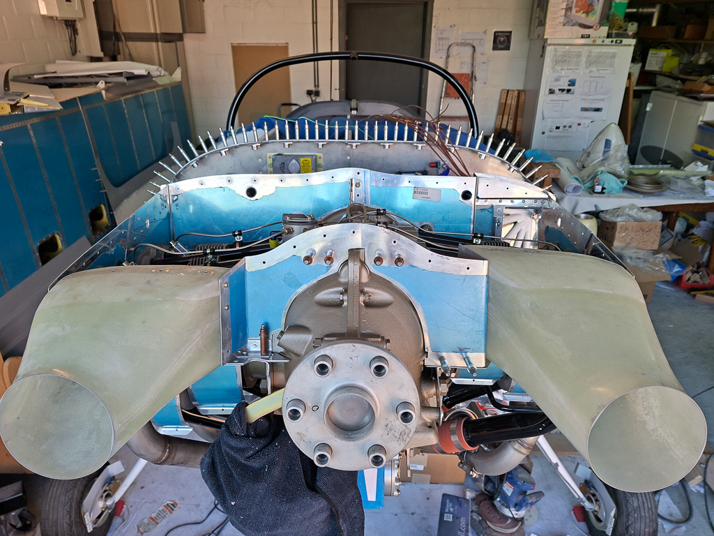
While working on the upper baffles and the ignition wire passthrough through the upper baffles, I had to measure how long the cables on the magneto ignition harnass actually are and how all of this actually works.
The box in my Superior IO360 engine box came with 2 Champion Slick Magneto's 4371 with impulse coupling on both magneto's.This is how a 4371 looks like:
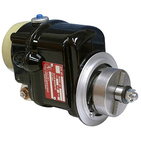
The magneto's were already mounted on the engine when I received them from PMM Wingservice but the plastic caps were still on. I still have to mount the ignition harness with the ignition wires myself.
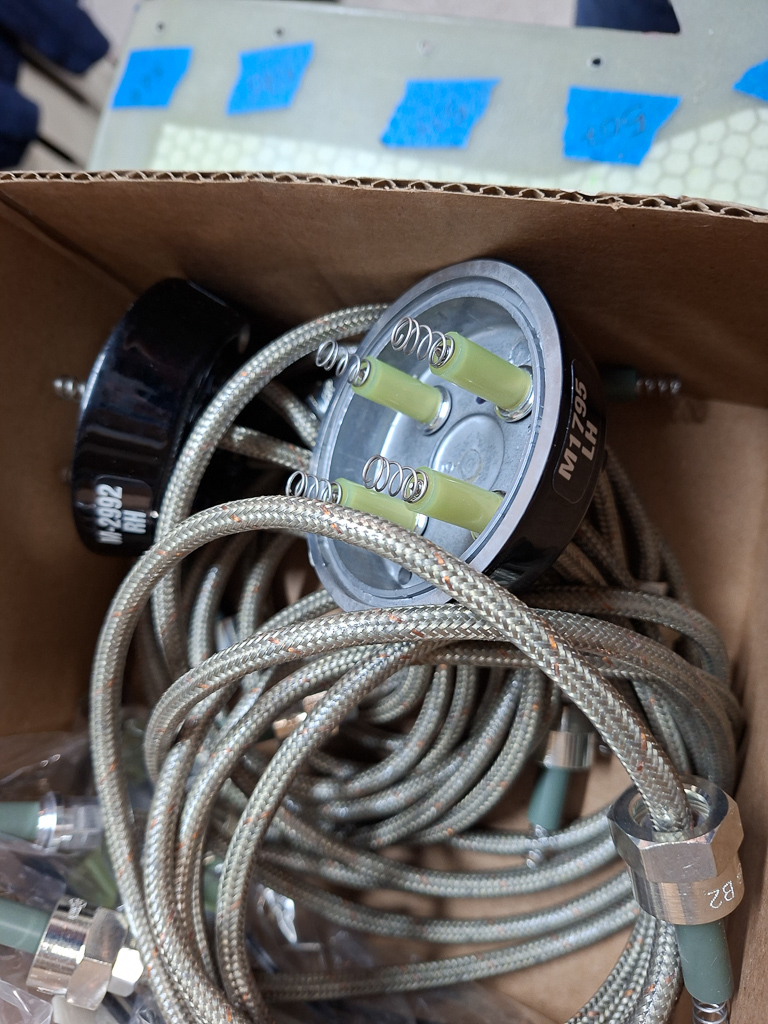
I opened the box and found this spaghetti of wires. I kind of worried on how to install these but it's pretty straightforward.
Each magneto head contains 4 wires, 2 wires go to the top cylinders and 2 go to the bottom cylinders. Eg one ignition harnass has the wires for Top cylinder 1 and 3, and bottom for cylinder 2 and 4.
Which cylinder to connect to is marked on the end of the wire on the nut that connects to the spark plug and has markings in this case like T1, T3, B2 and B4.
You can also see in the image below that the cover that is visible with the springs has LH marked on the head which is for LeftHand magneto.
The orientation is always seen from the pilot see forward. So LH is the magneto on the pilot side, RH the magneto on the passenger side.
Then the question is how these mount on the magneto rear side. After all, the spacing of the spring contacts is equal and you could turn is in 4 possible directions. It is important that firing happens in the correct order or you ruin your engine.
Well the good news is, you can't actually mount them wrong. If you remove the plastic cover cap to replace it with the real harnass, you will notice that the screw on the cap form a triangle. One of the sides of the triangle is longer than the other 2.
So if you measure where holes in the harnass are wider and mount them in the same position as the long side on the plastic cover was, you can't go wrong.
If you go wrong, you won't be able to screw back all screws into the rear of the magneto. If all screws fit correctly and you can torque them, you have the orientation right.
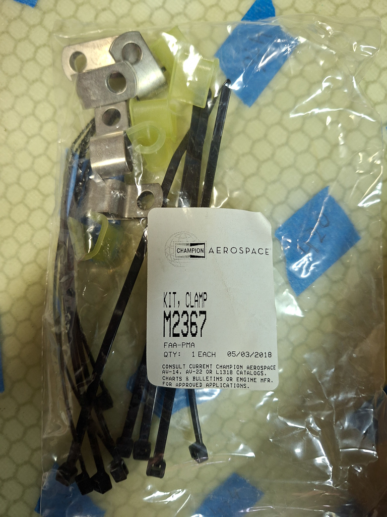
In the box, you also get some tyraps and some clamps and plastic inserts which are used to route the wires along the cylinder heads for the bottom wires.
I like that, but question is where the wires for the egt and cht sensor should go. I have to think this over.
With the baffles on, and as I want to get these finished before painting, I also had to think about magneto cooling ducts.
I looked up some builder references but the best image actually came from the RV14 installation manuel. This is a very good reference manual for firewall forward work as it contains much more information than the RV7 manual.
Here is a screenshot from the magneto cooling blastis as proposed on the RV14. It gives an idea on the routing within the engine mount, the location of the hole in the upper baffles and the location of ending the cooling tube on the magneto.
As seen here, you want the cool blast tube to hit the rear case to cool the electronicts of the magneto.
There is some debate whether these are really necessary but in my opinion you can't really take any risks on the primary parts of your engine. The cooling air will reduce wear & tear. It's hard to put a number on it, but magneto parts, points and even springs often fail from heat related issues. The hottest points are the coil and the area around the distributor housing. Cooling air aimed at the body of the magneto, especially around the distributor housing, helps reduce internal temperatures overall.
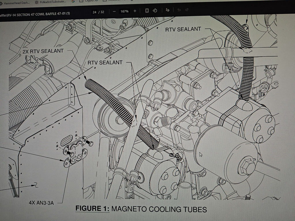
The pilot side magneto blast tube location is pretty straightforward. There is not a lot of options and the best location is probably the one as indicated on the RV7 baffle kit plans. The pilot side ignitiion wired pass right next to the oil cooler opening on the CB-705A cylinder 4 aft baffle and just below the CB705-B oil cooler brace so that area is out of choice. The next option is on the upper left corner of the CB-706A left aft case baffle as seen from pilot side.
On the passenger side things are a little more "free to choice".
I tried out various location like the one shown below, Things to look at are the distance from the engine mount, curved direction towards the magneto and where the bottom ends up in the most natural way.
The tube is attached to the engine mount with RTV and also at the magneto case.
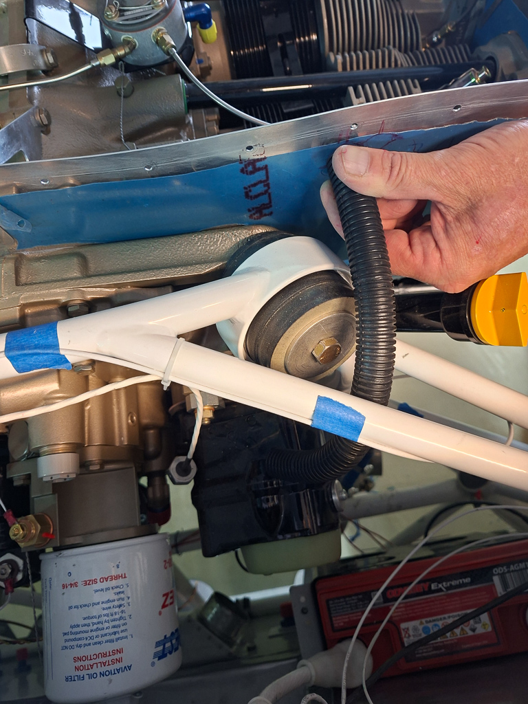
First I made the hole for the blast tube on the CB-706A pilot side. The opening is just below the flange of the plenum roof and next to the intersection of CB-706A and CB-705A.
The best way to do this is to use a step drill. The tube is 5/8 duct tube, also used as the conduit for wiring in the wings and fuselage.
The hole to drill only has to be as wide as the inner ribbles on the duct tube. 5/8 is the outer diameter of the duct, the inner ribble is only 11/16", so drill to 11/16 size for a snug fit.
This ensures the tube is stuck into the hole and can't move. Some additional RTV will keep it in place and seal it off.
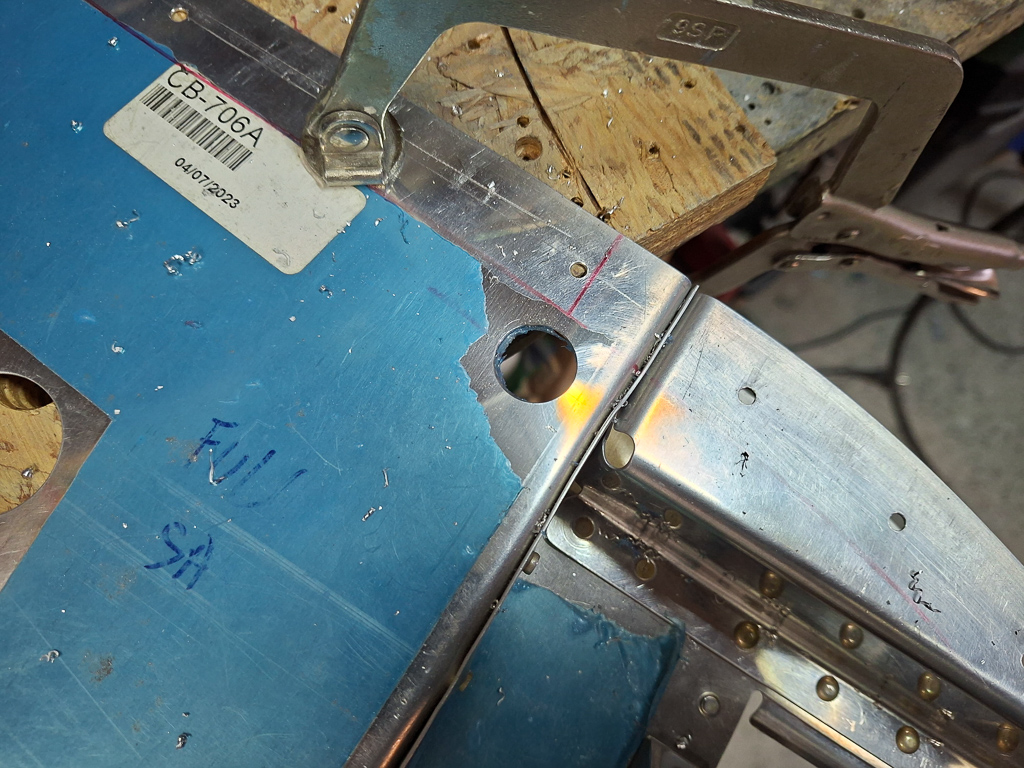
The I also drilled the passenger side opening which is a little more outboard than the one indicated on the plans.
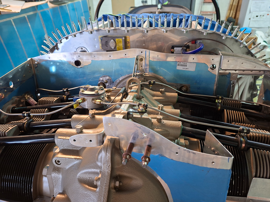
I test installed the tube on the pilot side and verified routing.The tube curves passed the engine mount where I will attach it with RTV. and it hit's nicely on the rear of the magneto case where the notch in the case is located.
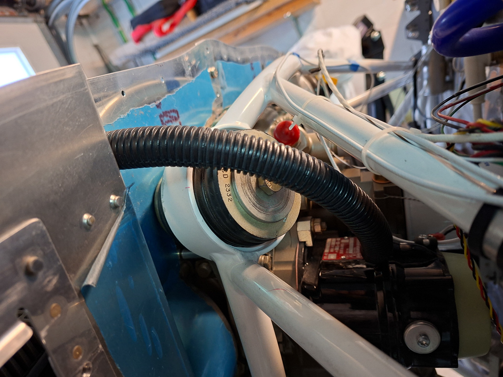
View from the front where you see both magneto cooling holes.