Day 3 on the baffle project. Work continues on the front side walls of the baffle cage. Most of the work and time is lost in deburring and cleaning the parts.
The interesting part of fitting the piece and rivetting the doubler parts on it is too short to compensate for the dull work of cleaning up the metal.
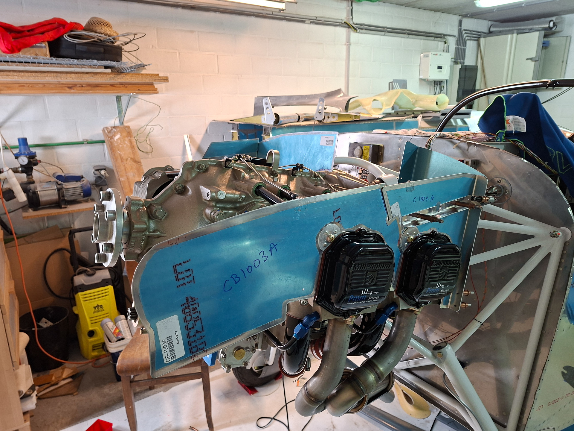
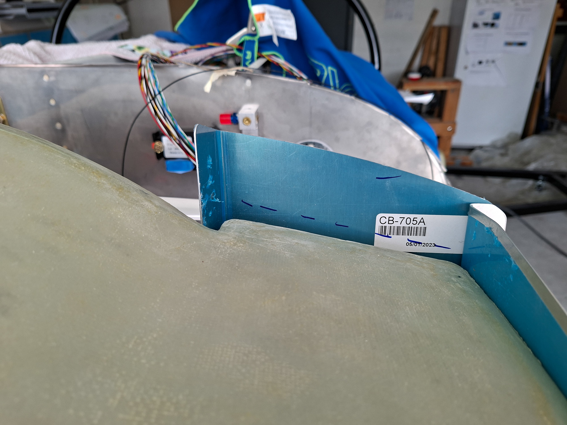
Installed the left pilot side front baffle CB1003-A
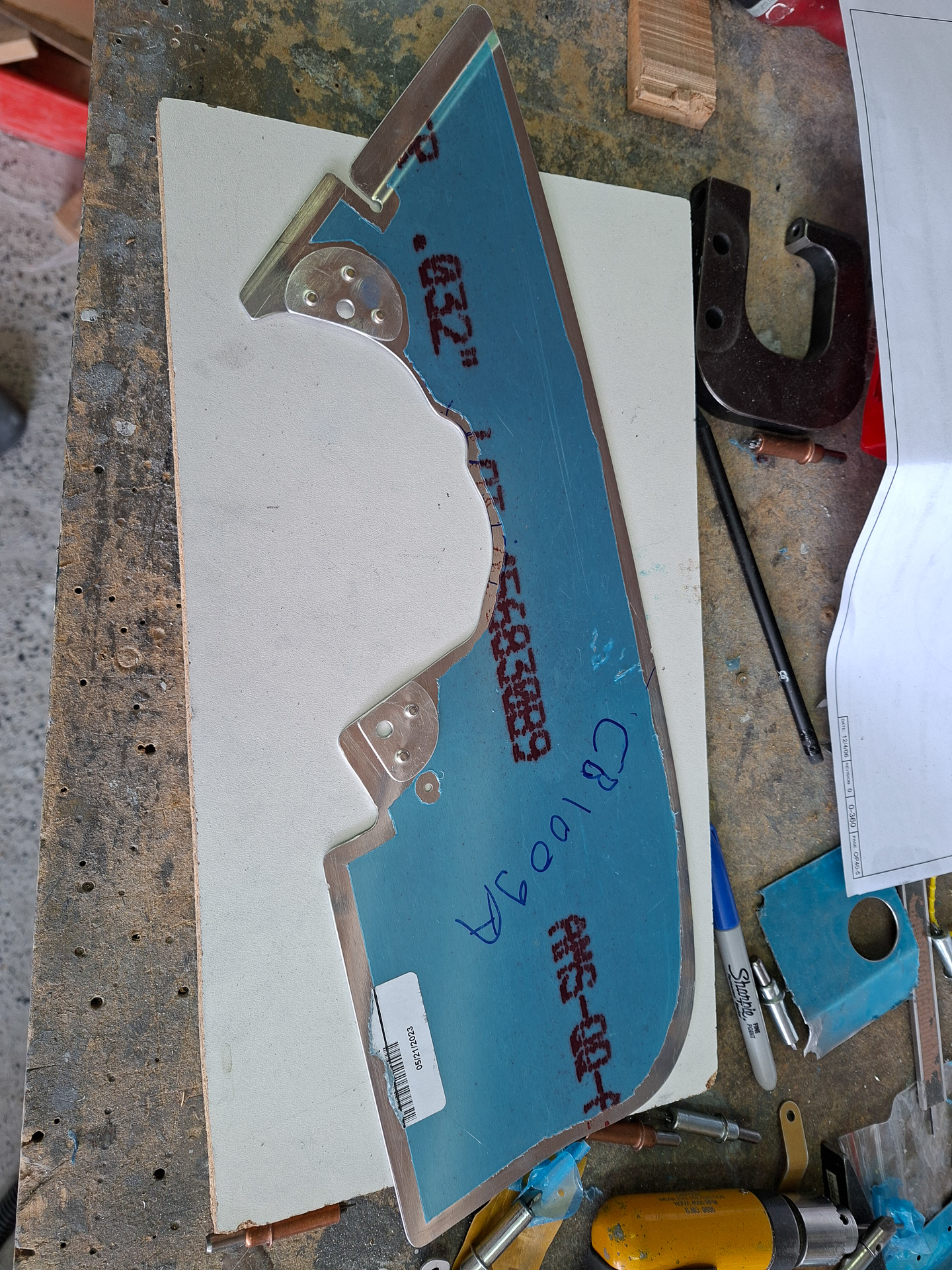
Then move on the the same piece on the other side called CB1009-A. More cleaning, more philing away material around the cylinder covers, 50 time on and off before finally being happy with the final fit.
Then installing the doublers on the 2 fastener locations.
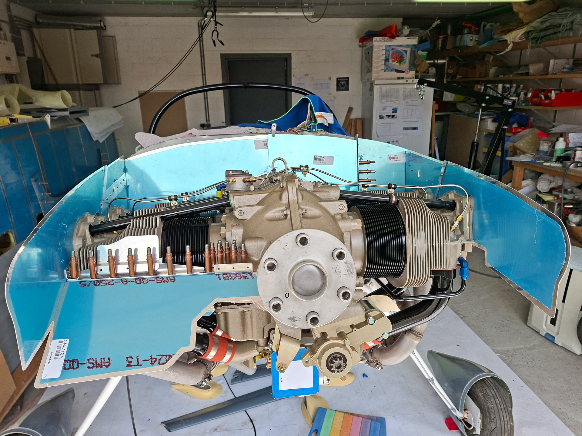
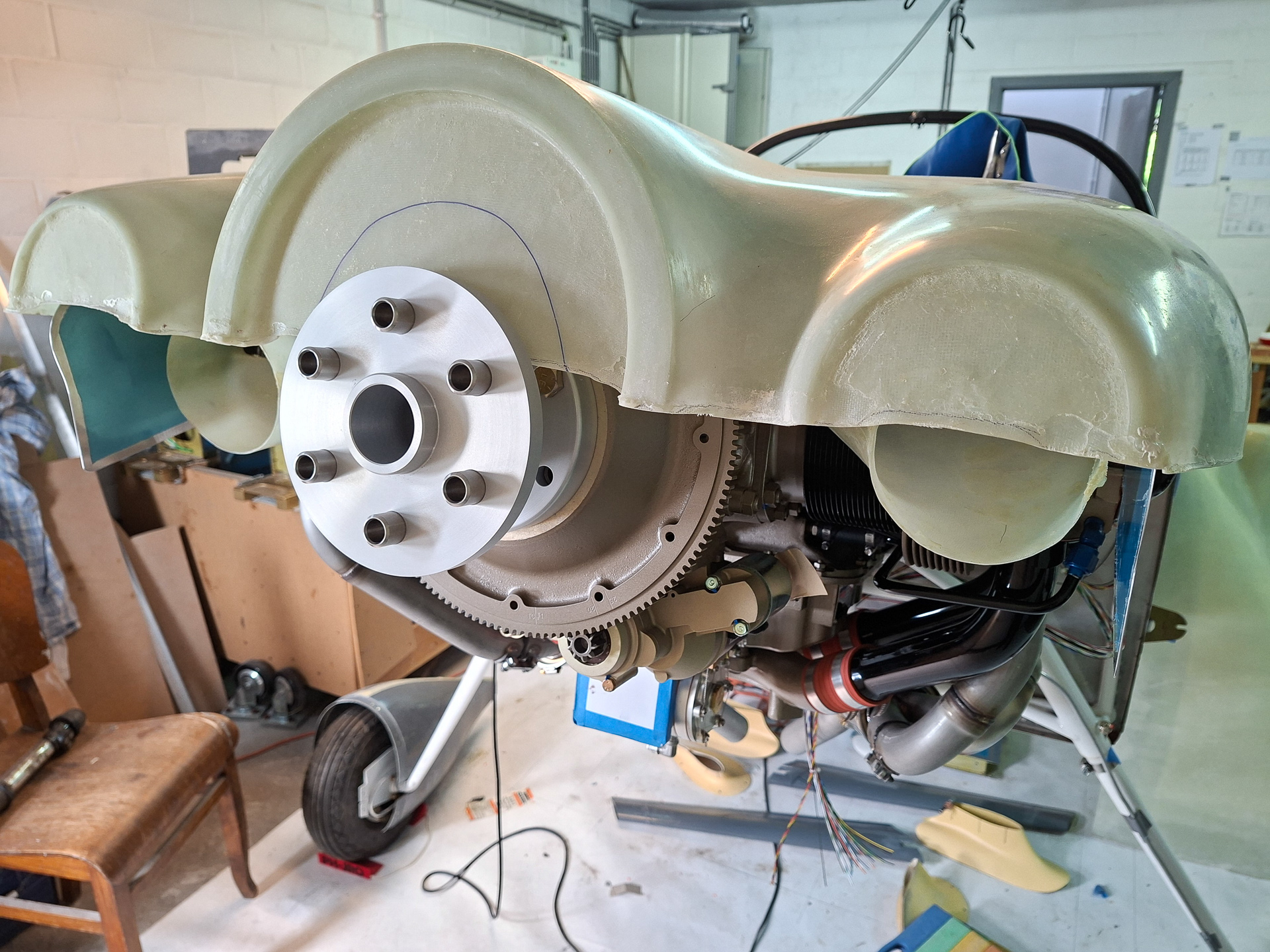
With the 2 front baffles in place, I was curious how it would look like with the plenum on.
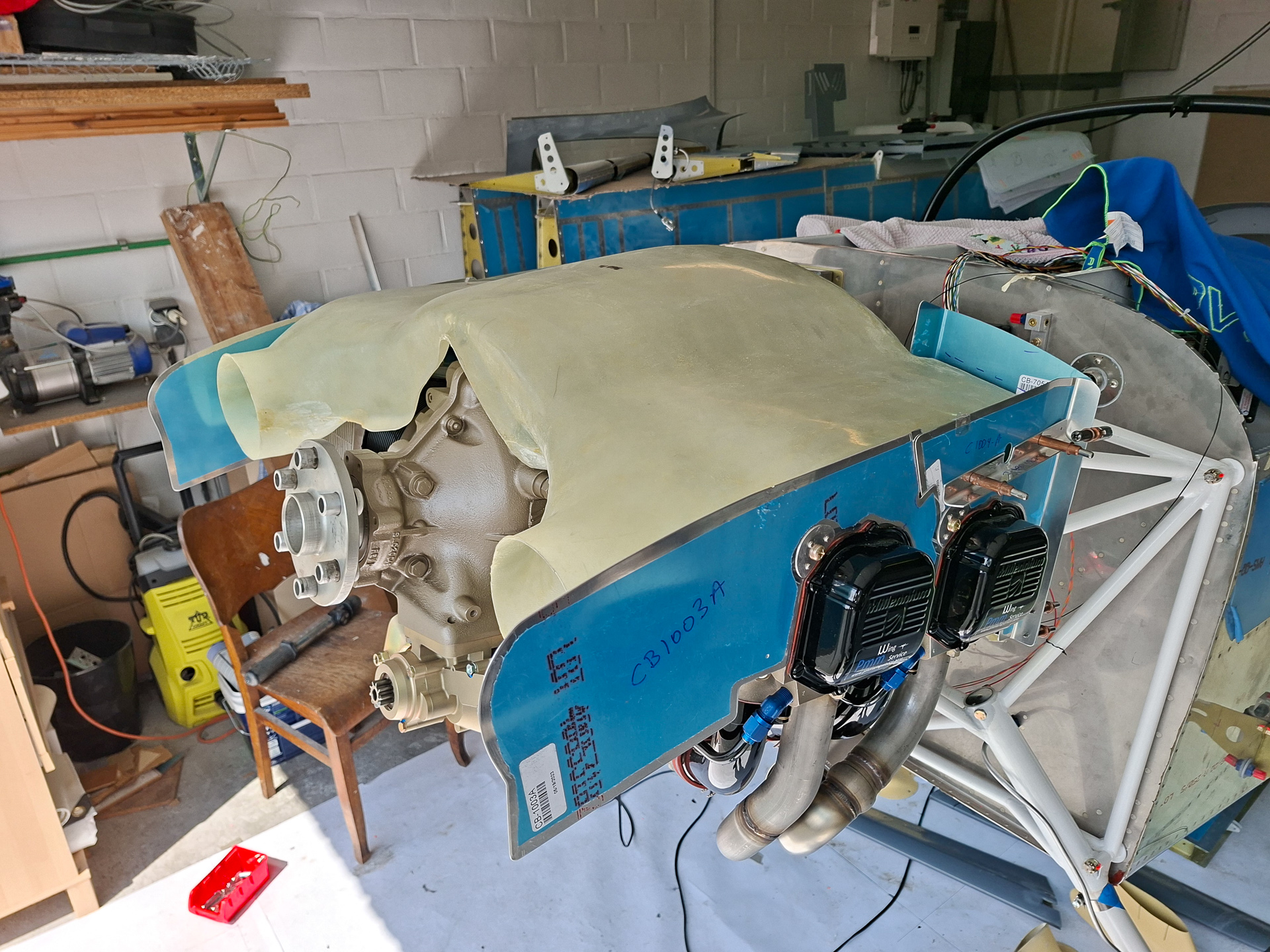
It's clear right away that the plenum will rest much lower and that this will seriously affect the position of the oil cooler in the back. A significant amount of aluminum will be removed from the upper side of the baffles. This is only an estimate but it will be at least this amount, possibly even more.
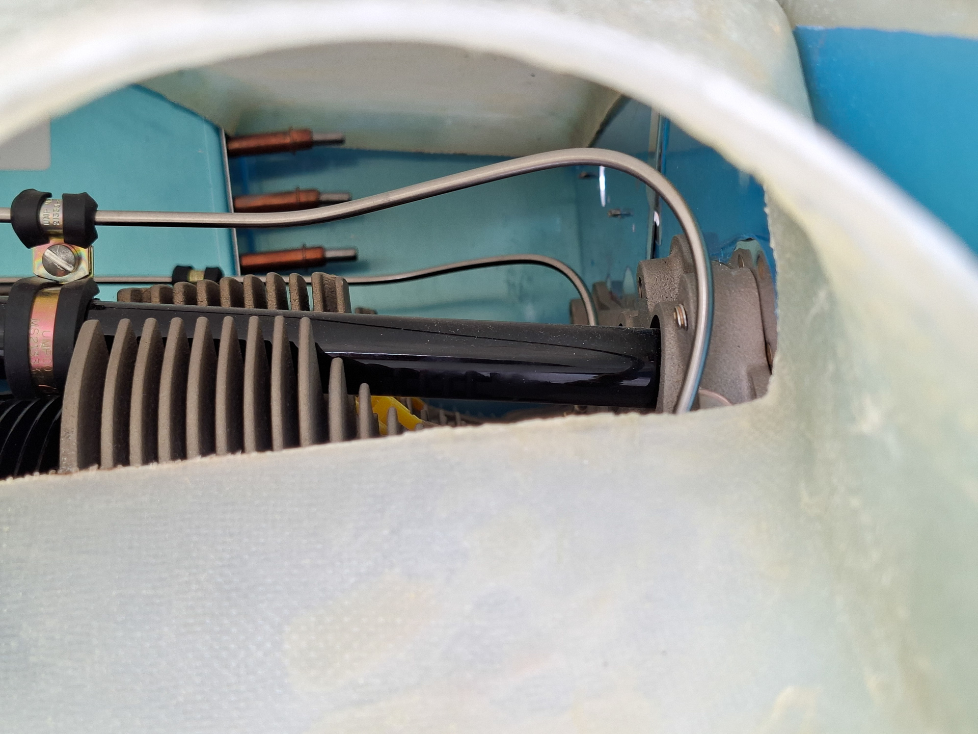
The picture below show a picture through the front air inlets. This will be even lower and it' s now clear that the clearance between the fuel lines to the nozzles and the ignition harness on the spark plugs in relation to the plenum will be very close. I read somewhere that it's recommended to used shorter spark plugs. I have to dig into that but will do that once I know if it's really necessary and the plenum height is defined.
Continuing on the forward air inlet baffles
The part on the left of the spinner. I'm sure this will have to be modified later on as Sam James has it's own air inlet and the ramps won't be required. It's unclear at this point which parts of the baffle kit from the front will be used and which are not used. At this point I may keep the vertical walls around the spinner and adjust the plenum accordingly but I'll have to discuss this with my DAR first.
Couldn't resist positioning the top cowl over the plenum to see how deep the plenum would have to sink to align with the top cowling. The top cowl is uncut and just resting on the crankshaft. I'll need to cut out the blue marked circle to see the actual fit. But it's clear it will still go lower.
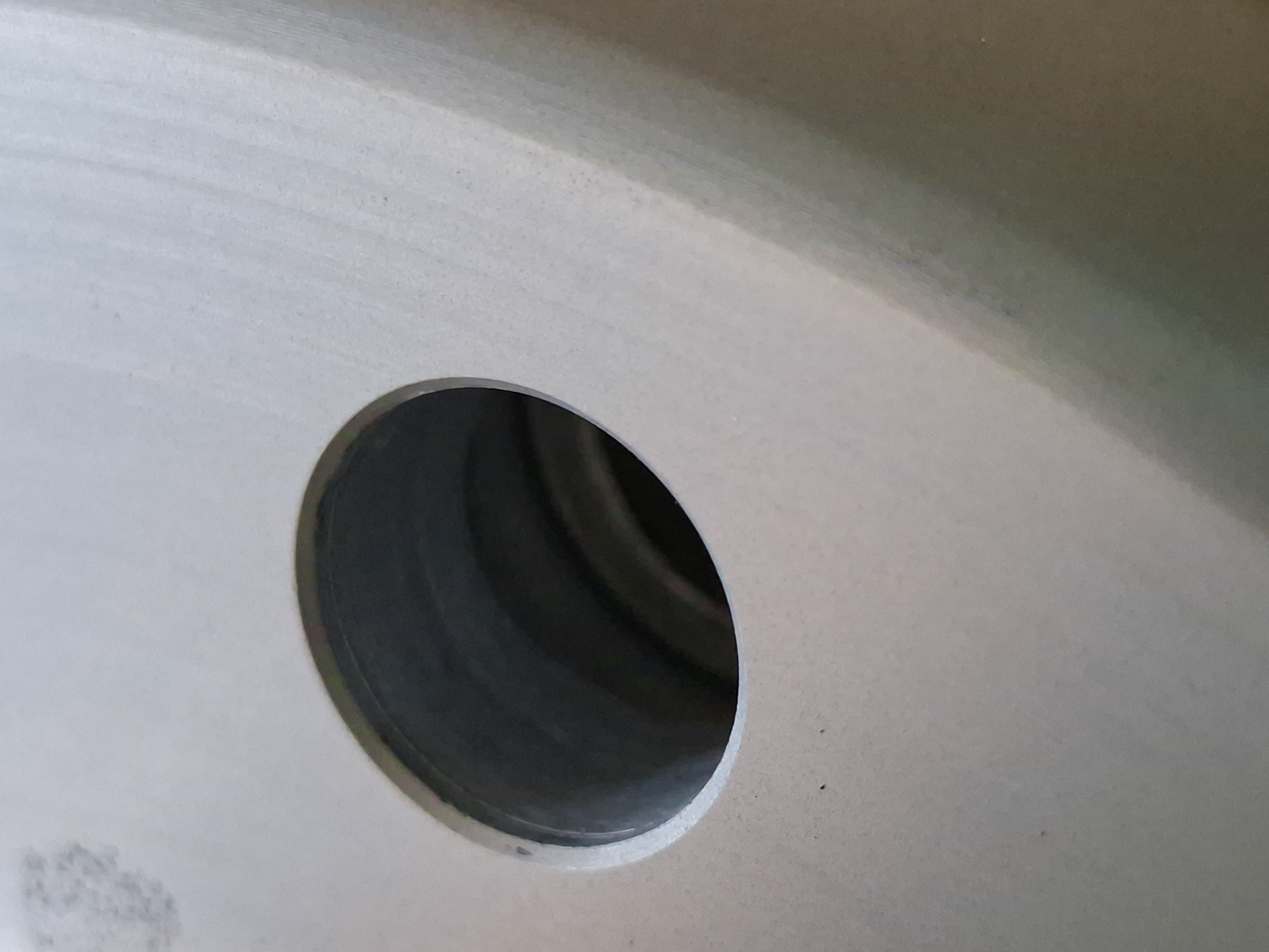
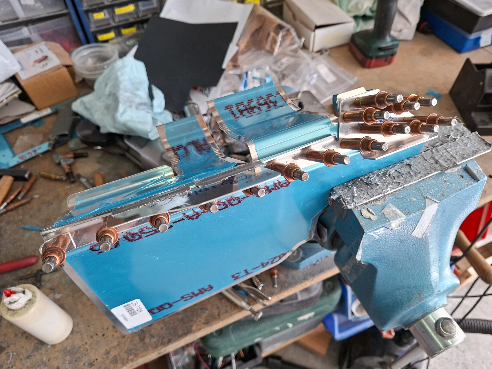
Another detail I noticed is that the lugs on the crankshaft are not fully filling the area available in the Saber Extension. The Saber Extension depth is about 0.6". The length of the lugs on the crankshaft is 0.6" but with the starter flywheel ring on it, only 0.34" is remaining of the lugs. That's probably normal but I'll have it confirmed
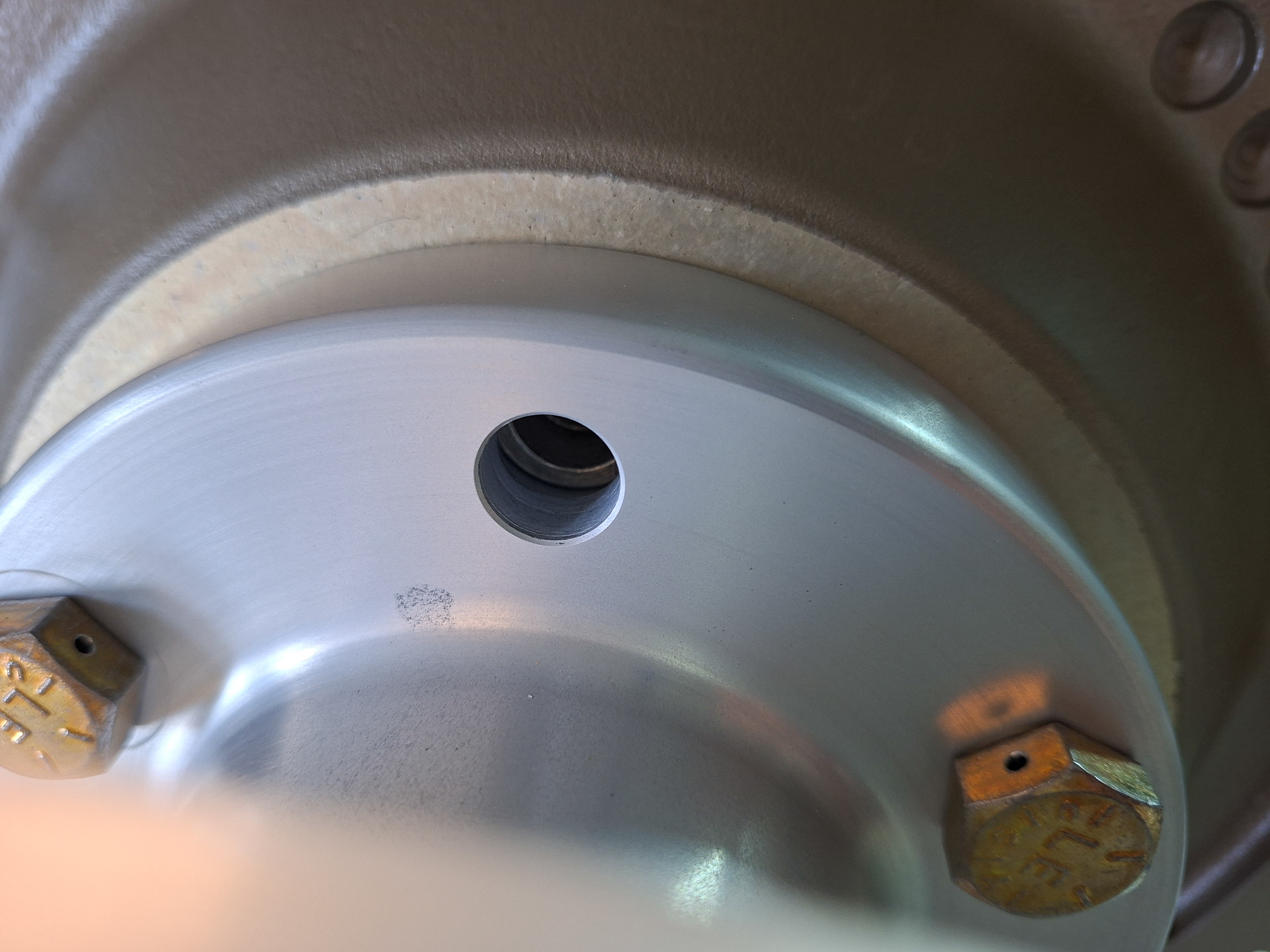
close up picture show this.