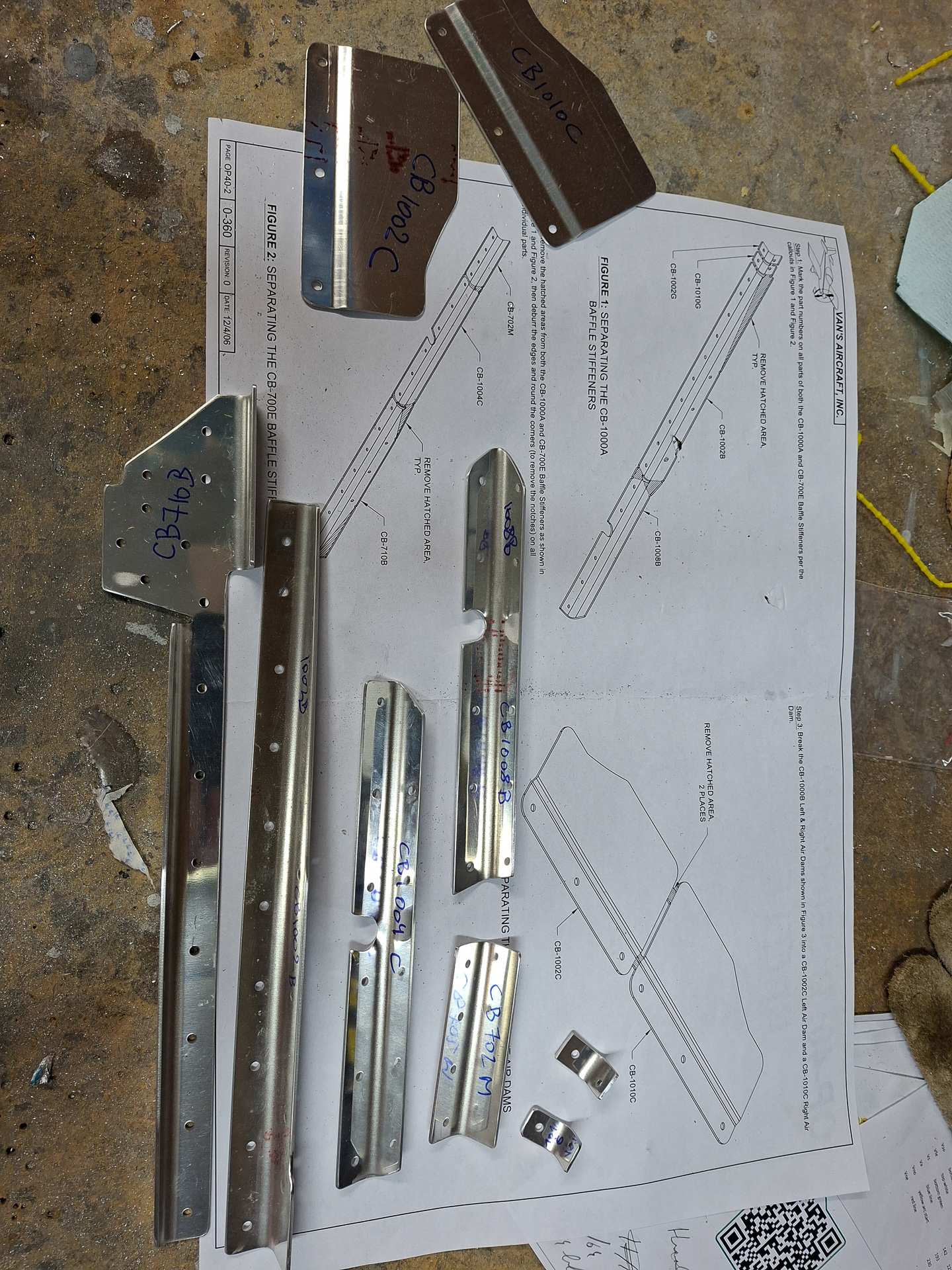
Day 2 of working on the baffle kit. Continued today with deburring and cleaning up of the small pieces as described in the beginning of the plans.
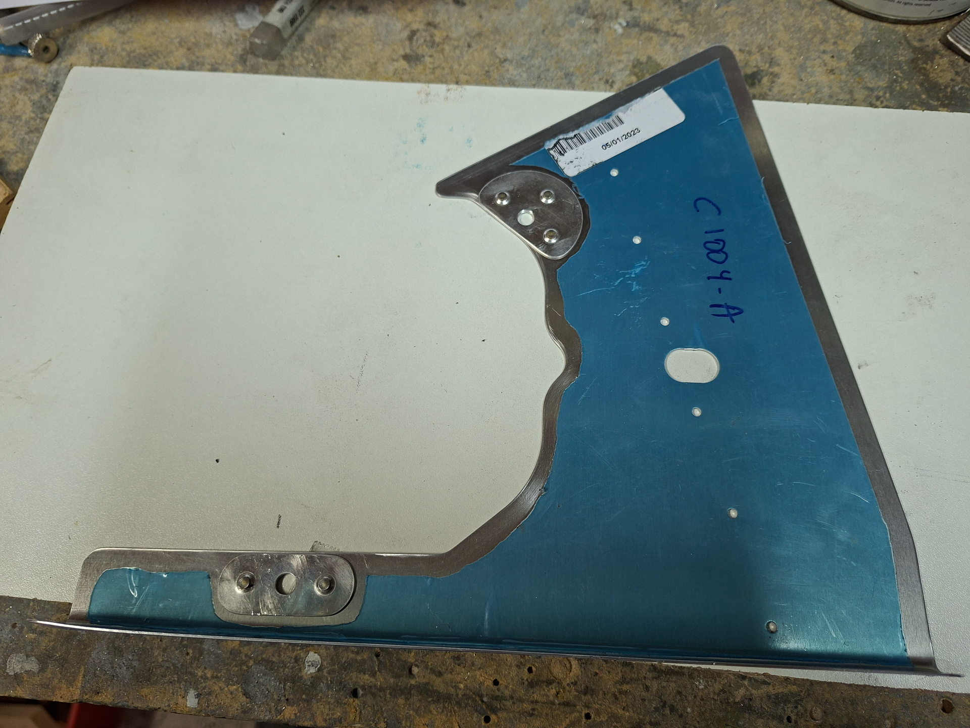
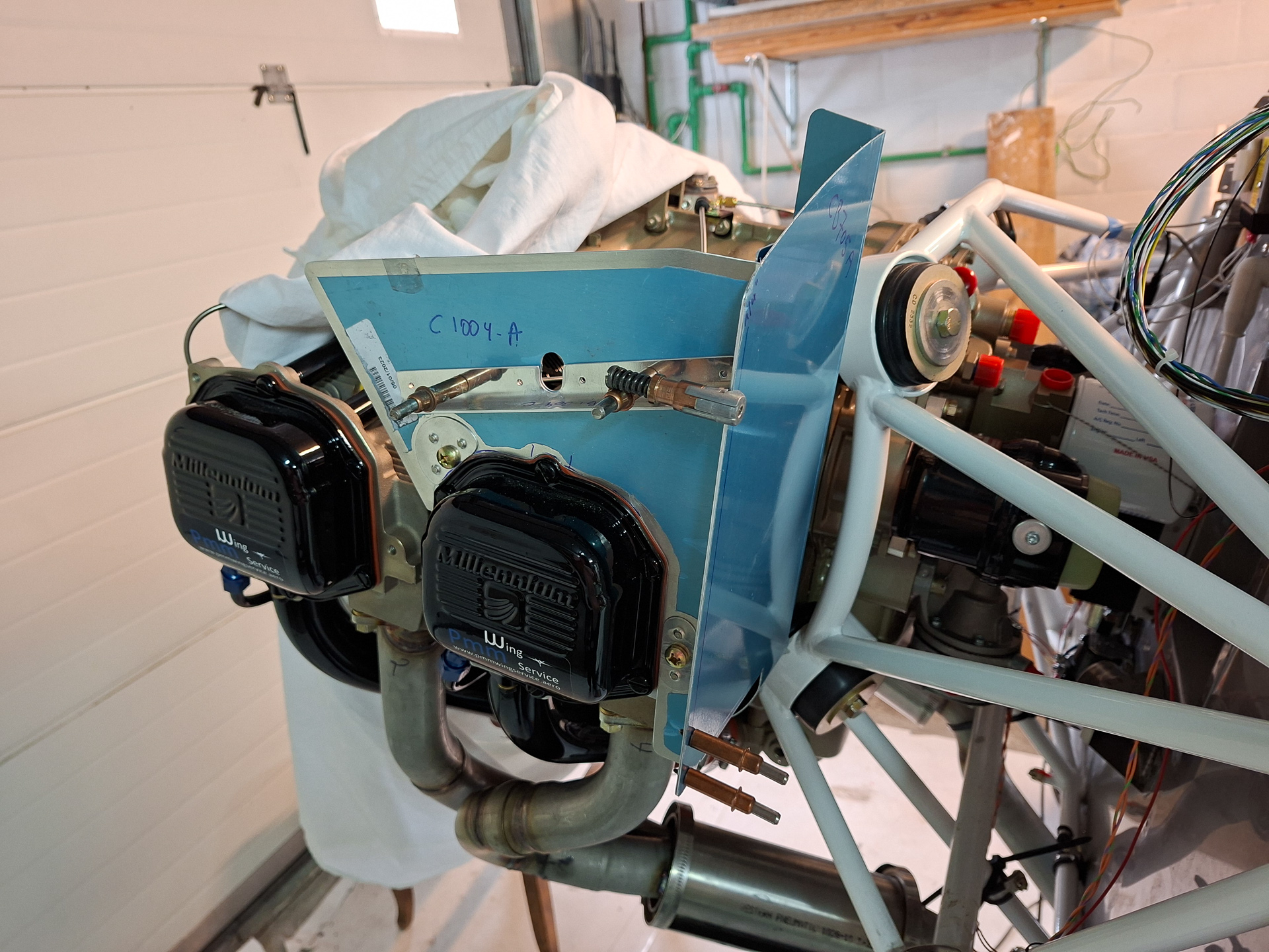
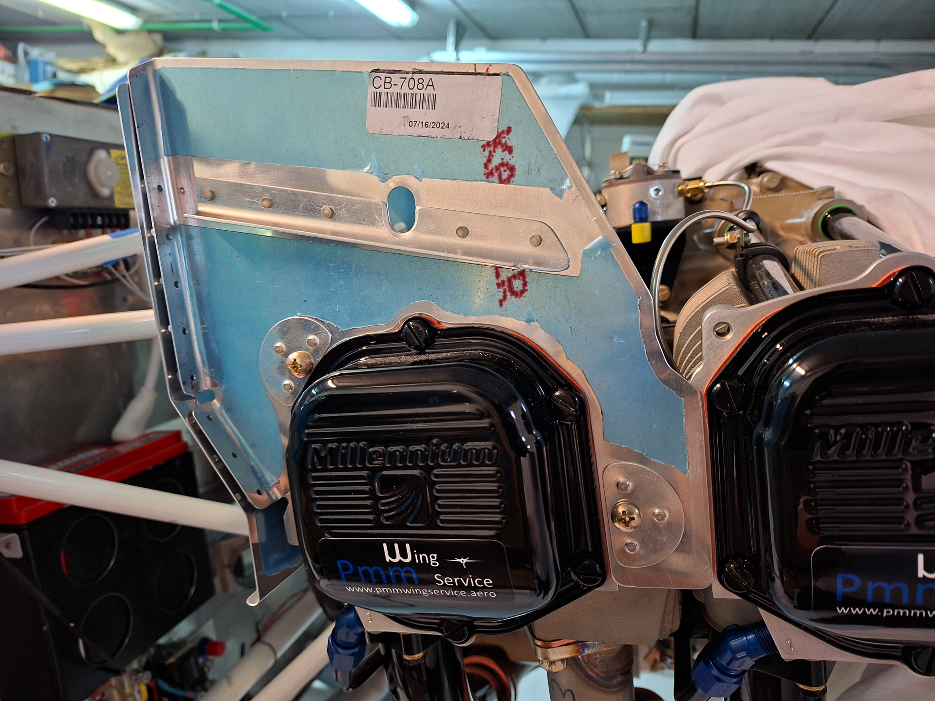
Next, worked on the pilot side rear side panel. These are very funky shapes and it takes a lot of work to get them in place. The picture below shows the CB-1004A piece that sits over the cylinder head (rear-left). The shape of the cylinder cover is cut out by Vans but it's an initial guideline and has to be further adapted to fit your engine. The rubber gasket between the cylinder cover and the cylinder body is also not taken into account for so you may need to cut out more to give room. You also don't want to cut too much as the fit between the baffle and the cylinder head needs to be tight so no air escapes. The whole deal of baffles is to create a high pressure chamber on top of the engine and every leak you have here will reduce the cooling capabilities for the engine.
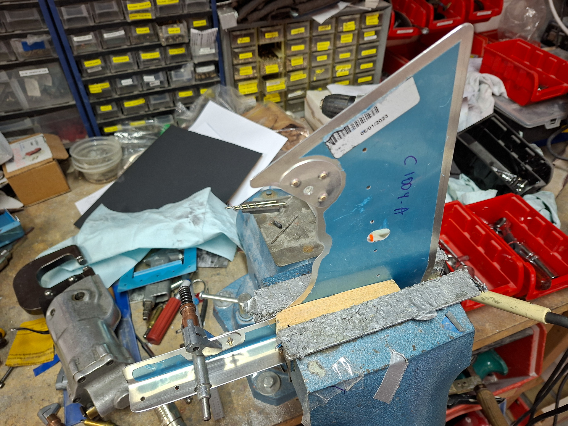
2 doublers are installed which reinforce the area where the screws are holding the baffle to the cylinder. The cylinder head had predrilled tapped holes that align perfectly with these holes in the baffle.
Next also deburred the rear left baffle. This is where the oil cooler will be mounted. The plans have you work on this and cut out pieces now but as I'm using the Sam James plenum, I can't really do that now. I need to know the exact height of the plenum before I can do any cutting. At this point, I started to realize that in order to know the position of the plenum, I need to have the exact position of the inlet holes of the Sam James cowling. Which means, I need to work on positioning the cowling real soon as all the rest is defined by that. In order to install the cowl, I'm wondering if I have to rivet my top forward fuselage skin... I really don't want to do that as there is some electrical wiring work left for P-leads, sensors, organizing wiring,... too much to think about...
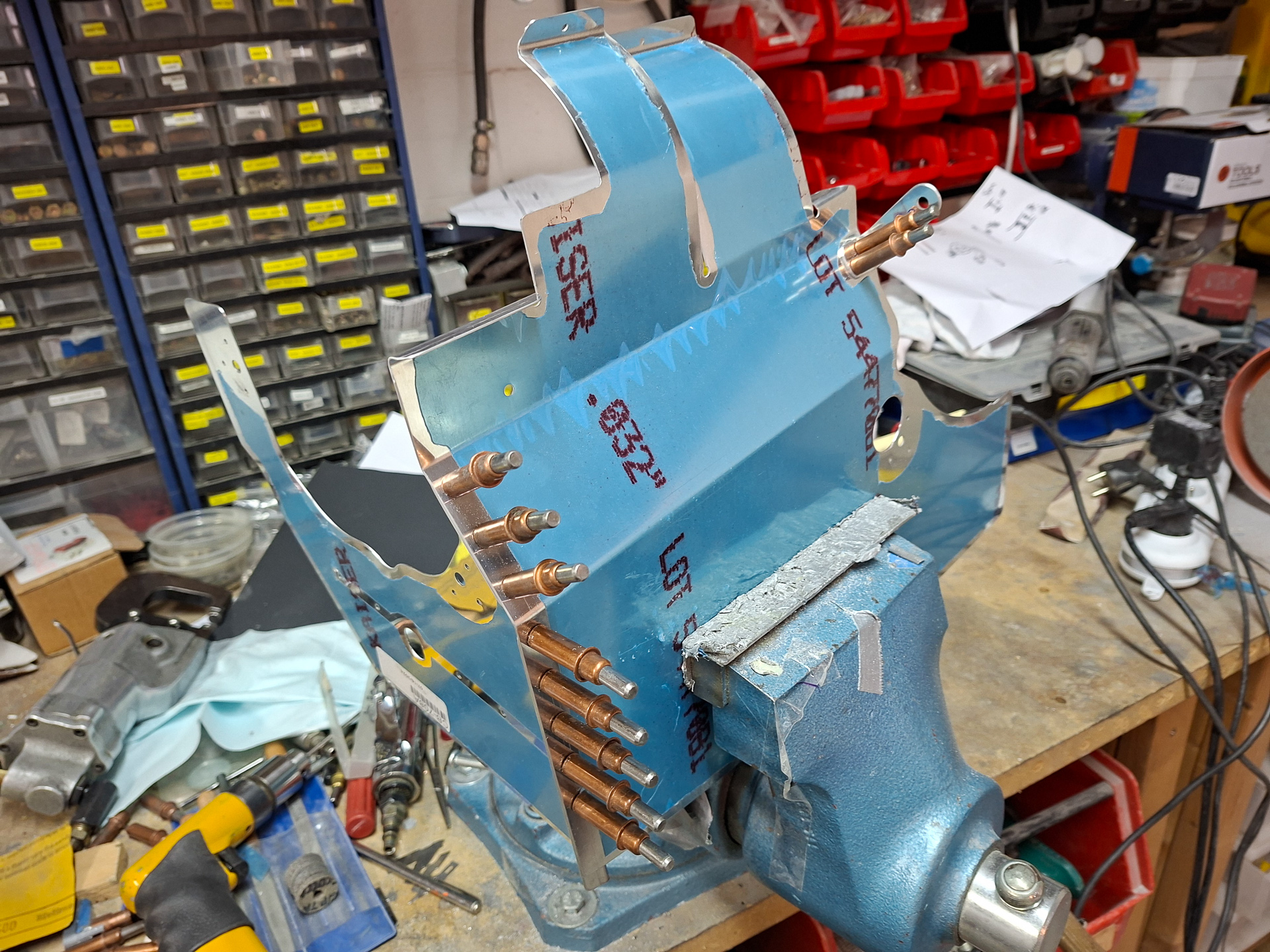
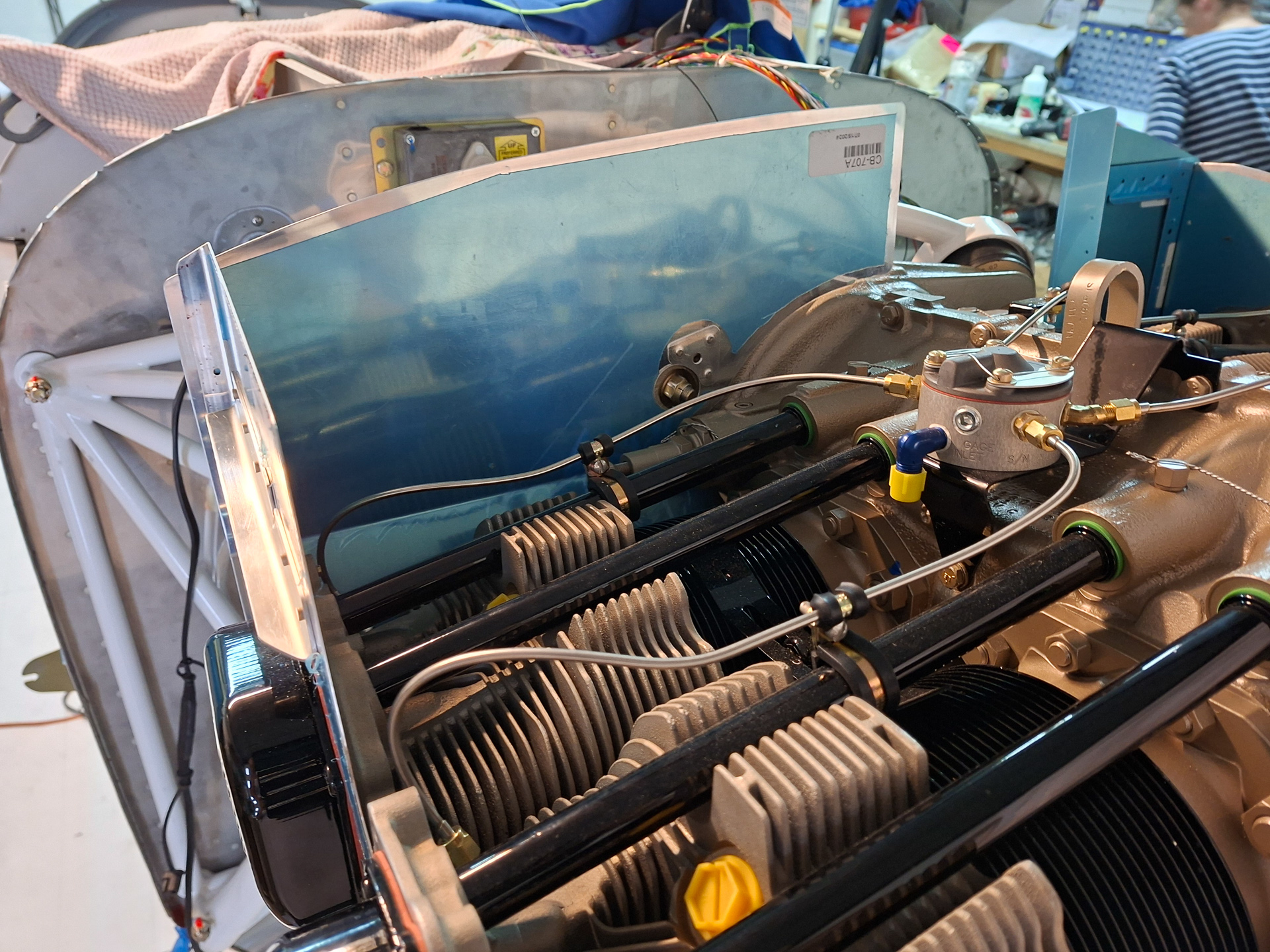
Moved on to the next part of the plans, working on the passenger side rear and rear side baffles. The circular shaped metal in the top are the fins that will be place underneath the cylinder and which guide the cooling air. They are annoying as you have to be careful while you are temporary fitting this that you don't ruin the paint on the cylinders
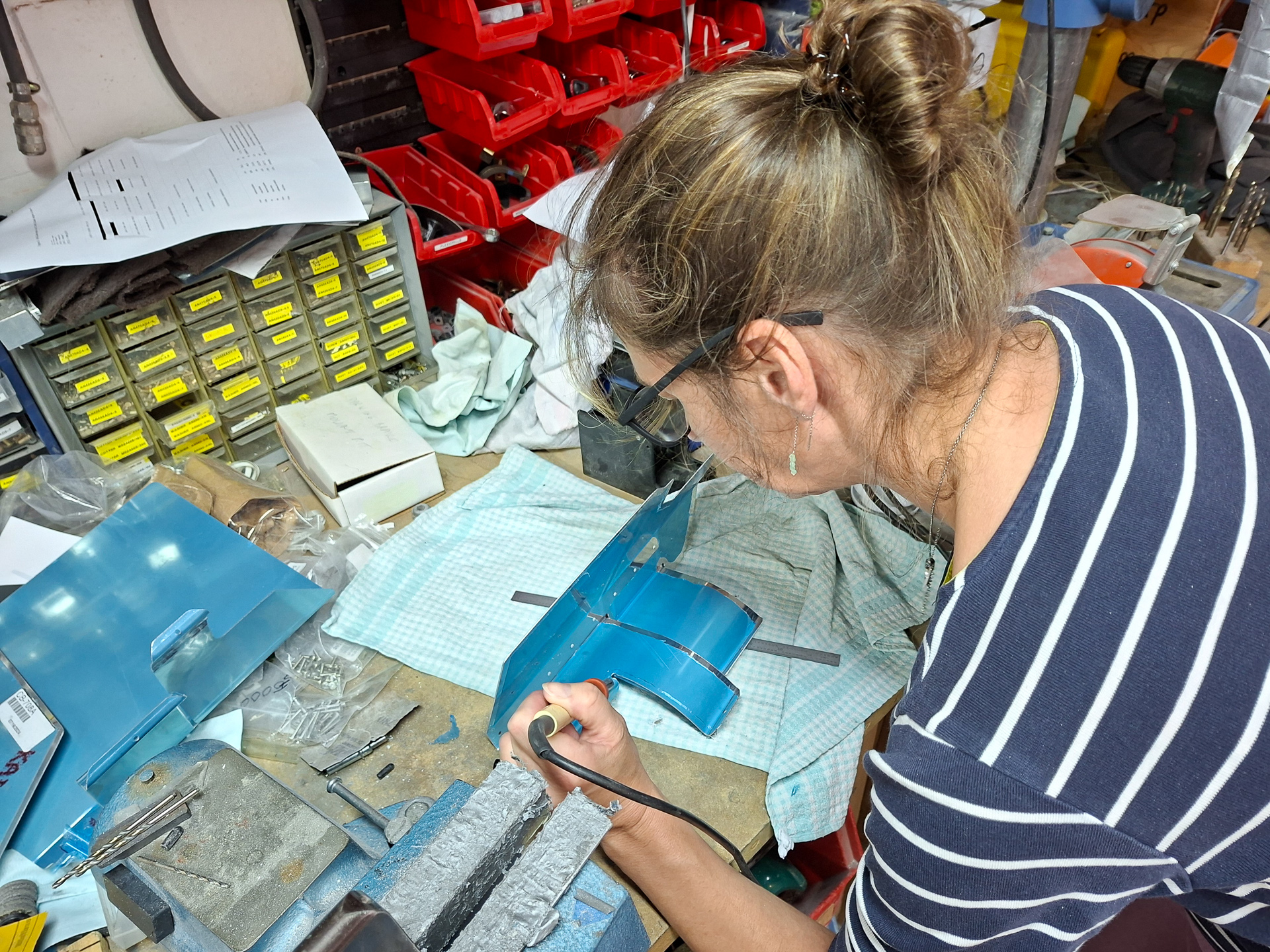
As I have been doing since the start of the project, I try to leave the blue protective cover on the aluminum as long as possible. This does give you some extra work with a soldering iron to free the edges that you will deburr. Fortunatly my wife Cindy gave me a hand here and saved me a lot of time.
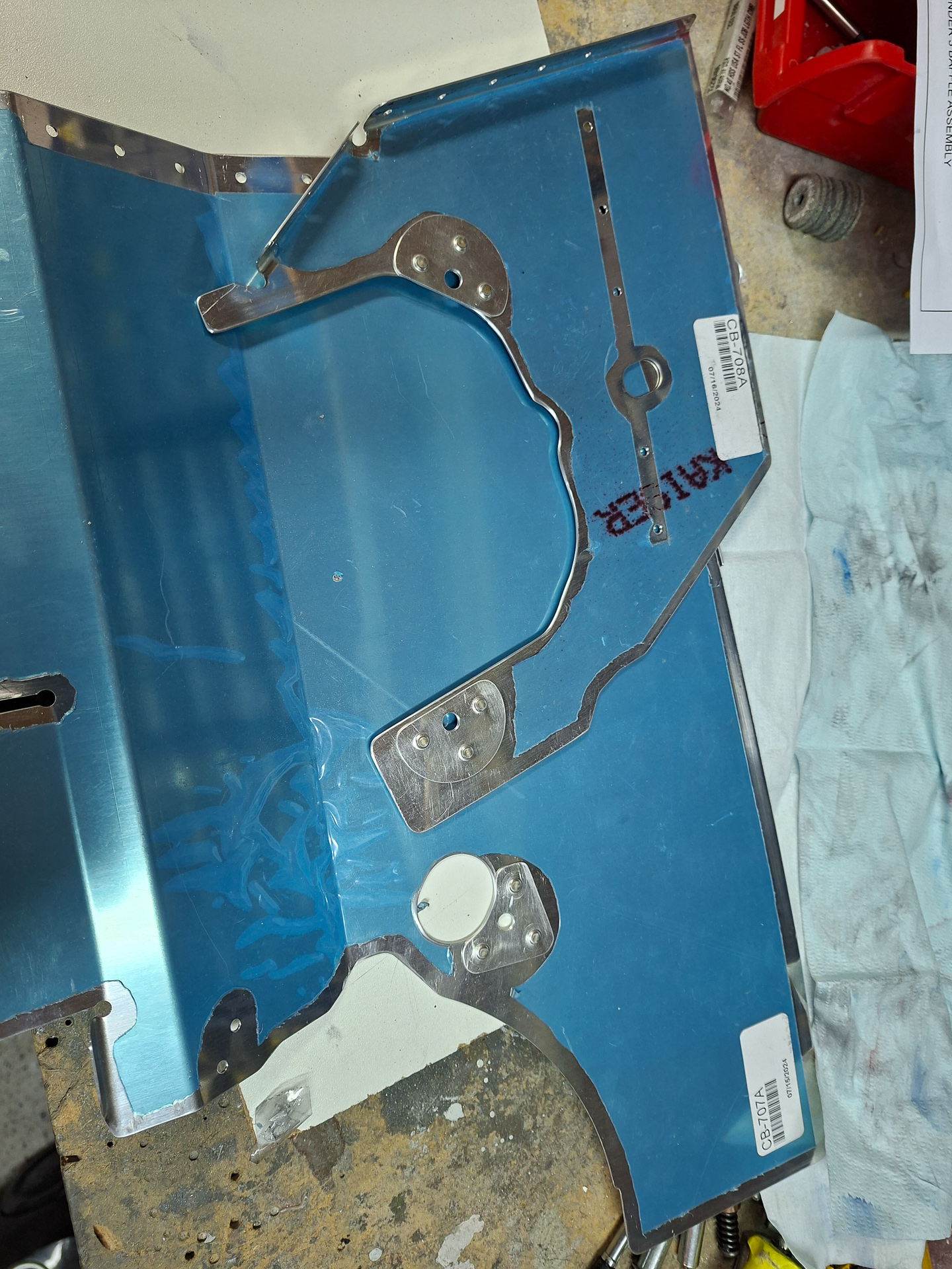
2 more parts done and doublers rivetted on.
Installed it on the engine. Some people have reported a gap needing a shim between the two parts but as I rivetted them together, they looked pretty close and I couldn't see the need for any shimming here..
Top view of the same parts.
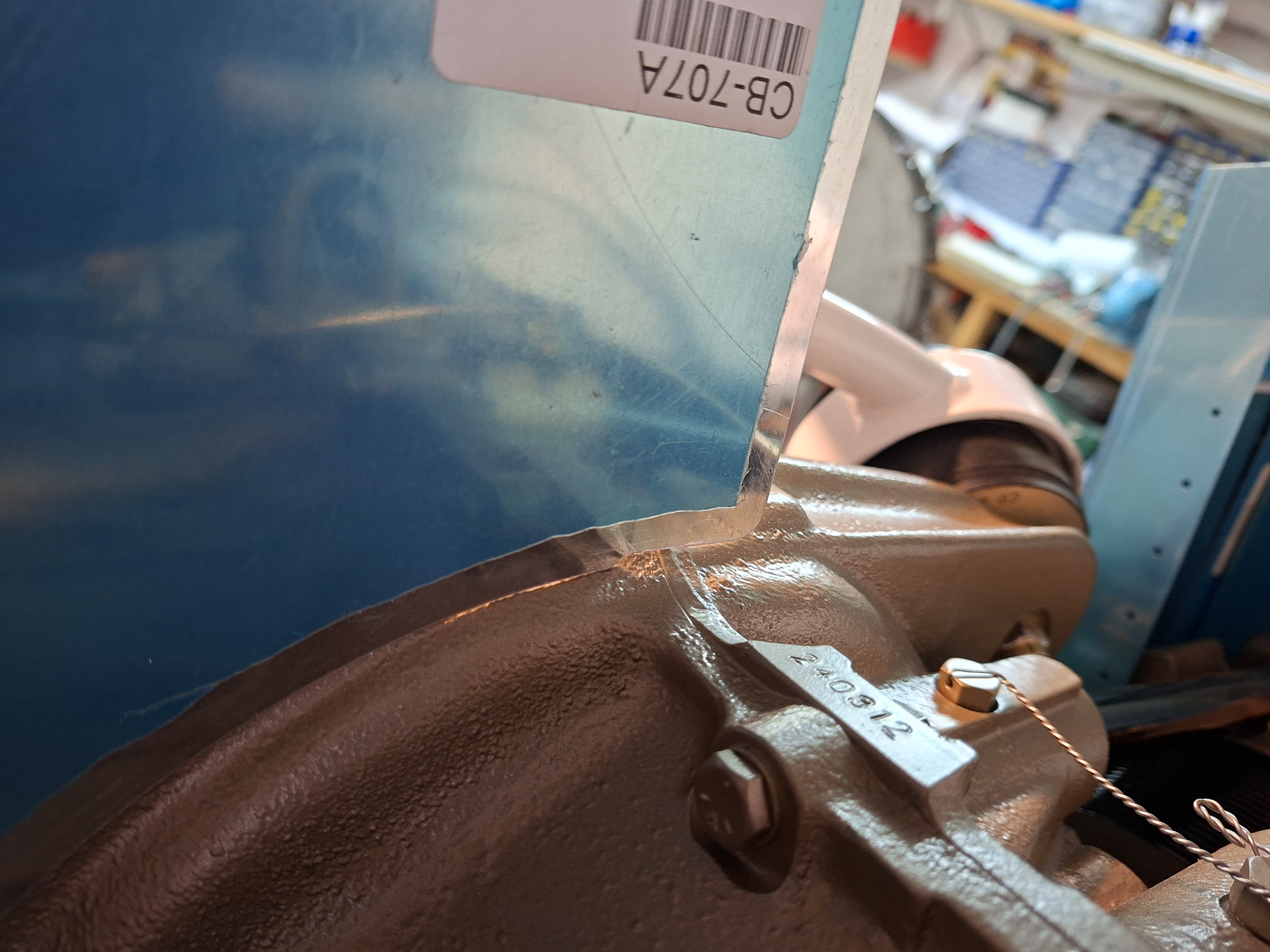
I needed to remove some extra material on right bottom side as the baffle was interfering with the engine case.
I had a lot of issues getting the circular bottom cylinder cover over the cylinder and trying to get the part on and off.
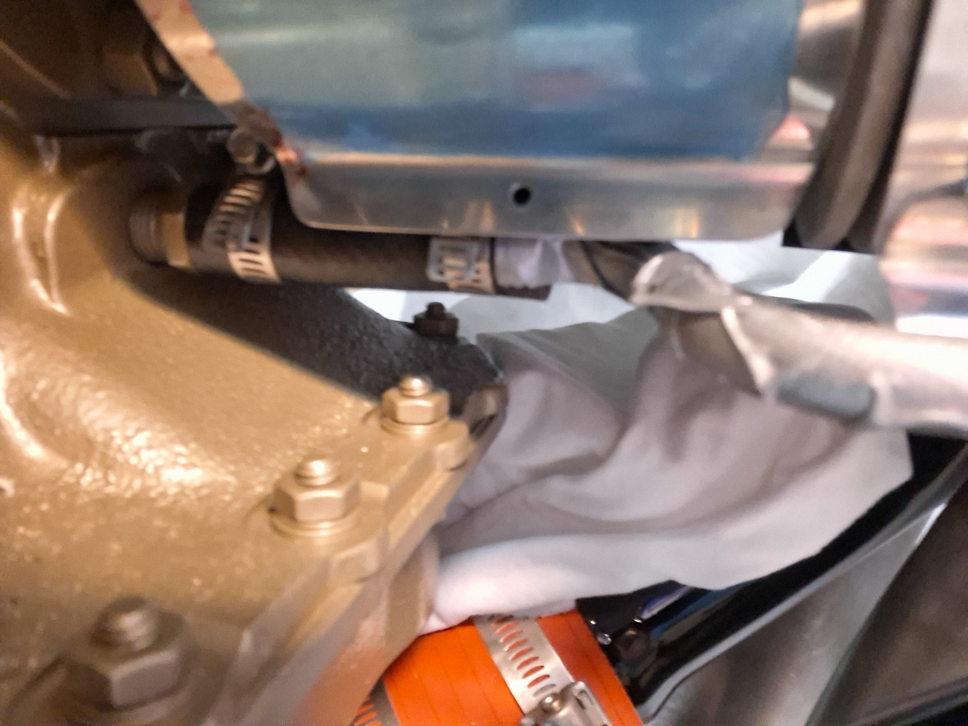
Finally, after a couple of iterations I realised the hardware steel clamp over the black rubber hose was preventing the baffle to move over it.
I could simply fix this by loosening the hardware clamp and reorienting the locking part by rotating it 180° towards the bottom. Now the baffle can slide nicely over the rubber. In the image below you see the problem before it was solved. the clamp had the same position as the one you see on the left where you can also see the locking part sitting high over the rubber hose.