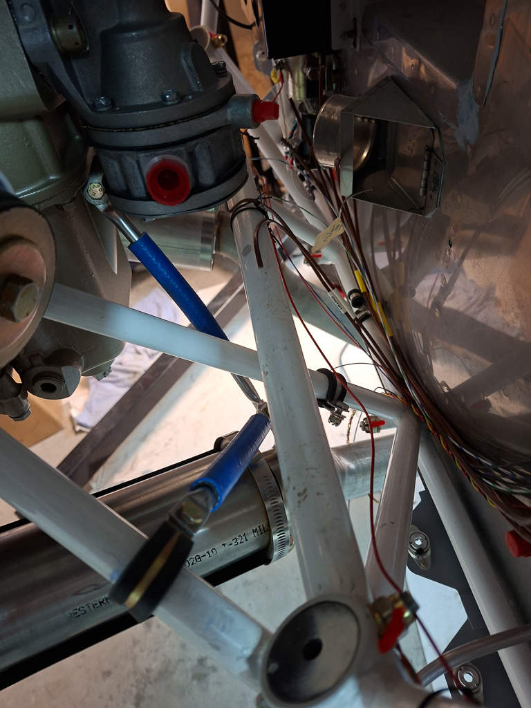
Yesterday Danny visited me in my workshop. A long awaited support visit for my ton of questions. Danny has been flying his RV9 for more than 1000 hours now and it's truly a beautiful machine.
One of the topics that was open for a long time was how to hand the support brackets of the exhaust. The mufflers were kind of in the way and hanging the clamp lower below the bend was creating even more problems. Danny gave me some good ideas on where to hang them and reassured me that the clamp next to the muffler would be no issue.
My exhaust is already super rigid as I don't have any ball joints, there is almost no movement when the exhaust pipes are tight against the engine block.
Today I started experimenting with the exhaust support brackets on the pilot side.
I plan to hang to inner bracket from the corner engine case bolt just behind the mechanical fuel pumpt. I needed to use the 45° steel angle as also indicated in the Vetterman drawing.
Vans OP-54 plan shows a nice picture on the distance required between the support tubes.
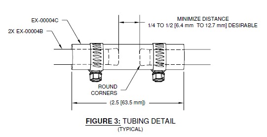
The plan indicates you want 1/4" to 1/2" inch distance between the 2 ends that sit beneatch the blue rubber tubing.
They also tell you to flare and round the end of the tube so that the hardware clamp is more rigid and has less possibility of coming off the tube.
I had to bend over the hanger on the exhaust clamp to get the good angle towards the ending side bracket. It takes a bit of fiddling and bending back and forth but it's not all that difficult to finally come up with the right angles. All you need to take care of at this point is that the way your hanger is rotated and bend, still allows you to reach the engine mount bracket on the other support bracket.
In the image below, I have the inner support bracket ready.
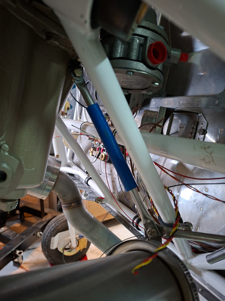
Then I head 2 options for the outer bracket. I could either attach it to that thick horizontal engine mount bar but the distance is really short here and I would have to seriously cut back on the tubes leaving little to flex and clamp on. Not a good option.
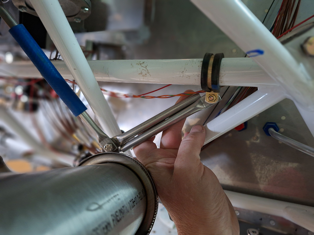
The other option was the rising bar from the landing gear leg to the engine cup. It leans a little backwards as well and I will need an additional tab bend at 30° to be able to get a direct straight line to the engine mount.
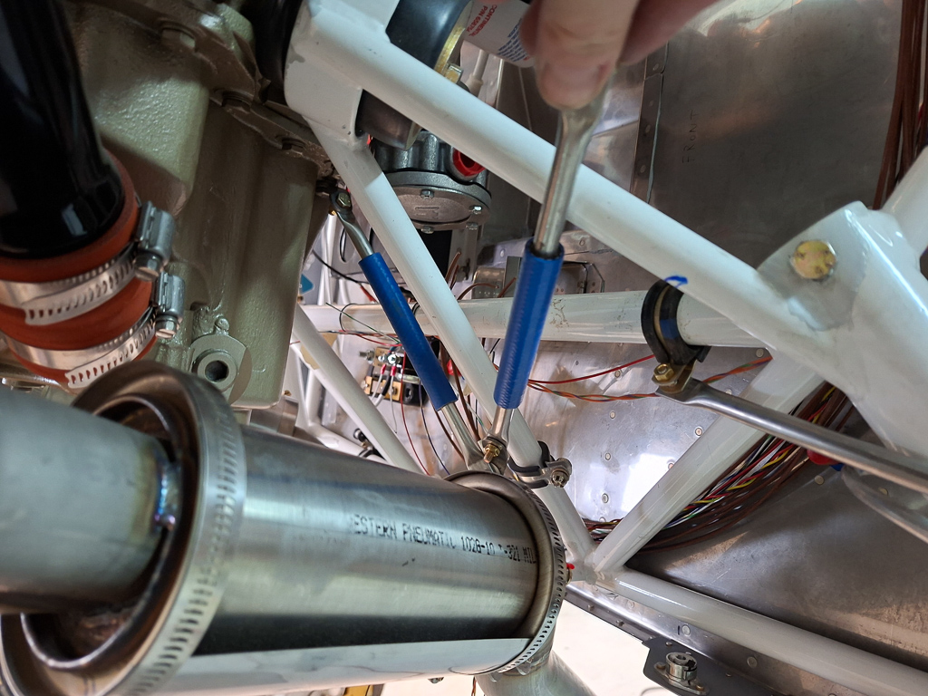
You can see I made a small tab in aluminum here to test fit. I will need to order some steel sheet to make this part out of steel. It gets pretty hot on there so I assume steel is inevitable here.
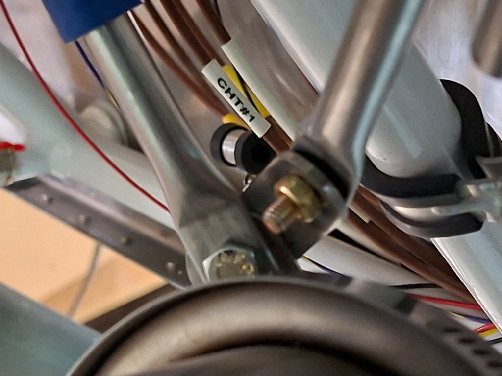
Both support brackets are attached. Here is a view from the front.
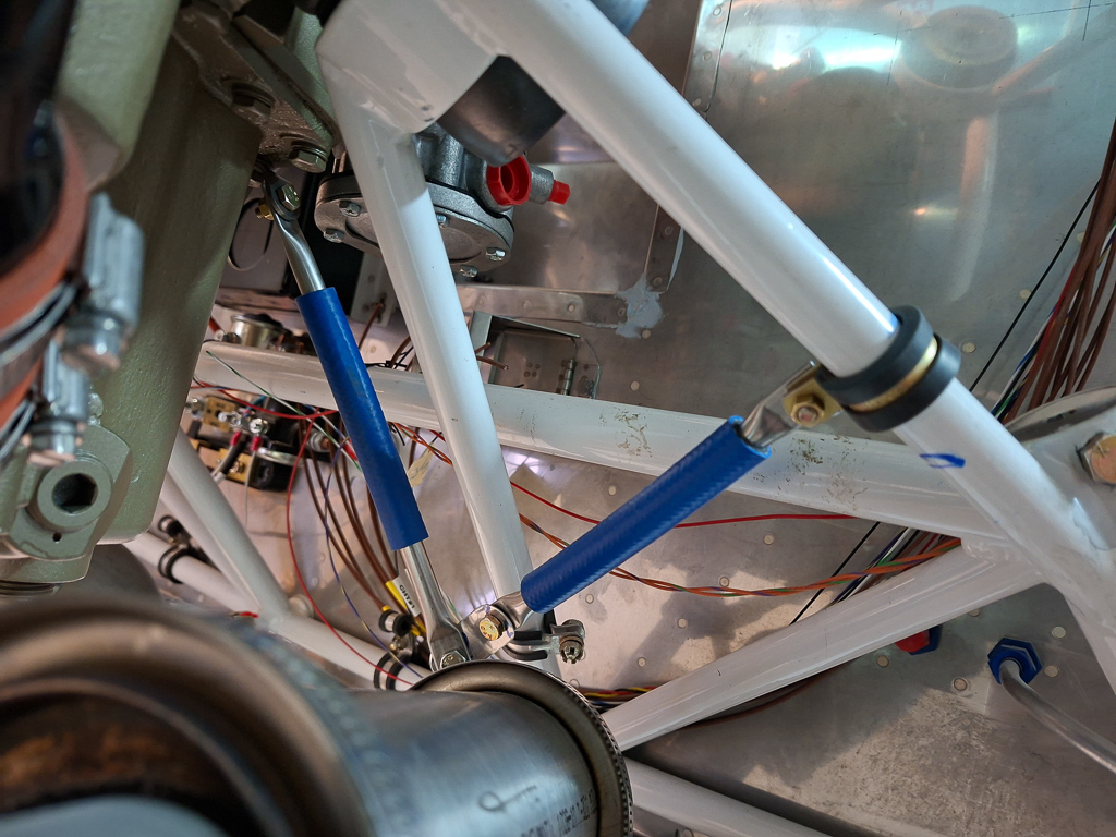
And a view from the side. I'm pretty happy how this turned out. Next I will do the same thing on the other side.