
Continued on the exhaust support brackets/hangers.
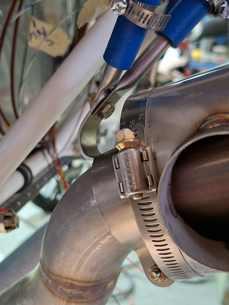
Here is a close up shot of the hardware involved. The rubber tube remains untouched unless you have a very short connection between the 2 tubes (in which case I wonder if you have chosen the right location for the brackets).
The tubes get cut to length and have 1/4 to 1/2" inch of void space between them. The blue rubber slides over the tubes and makes it a flexible connection. (vibration remember...)
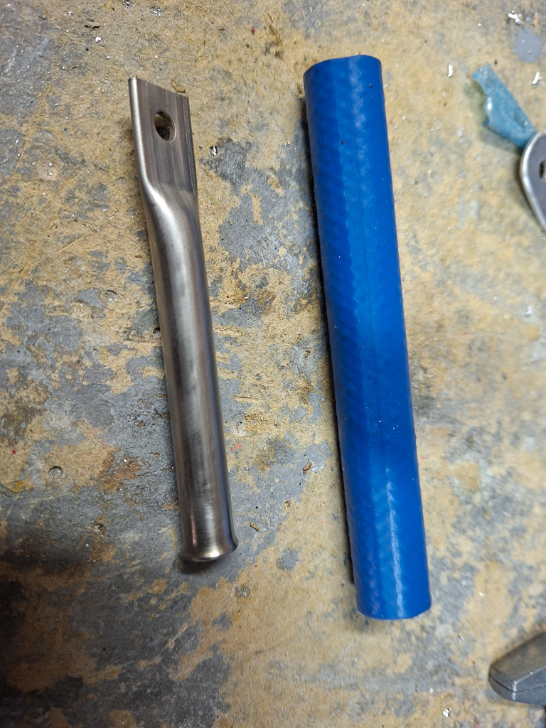
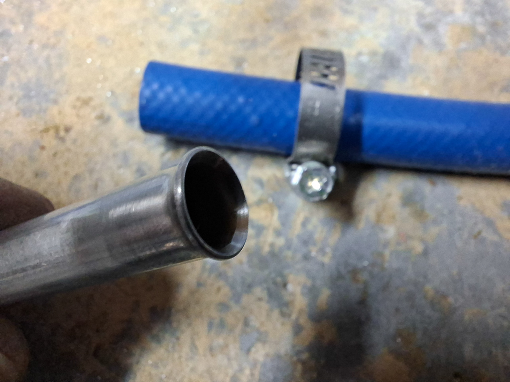
It's a good idea to flare the end of the tube a slight amount. A small amount is suffient. Going too wide will make it difficult to slide the blue rubber over and might potentially wear out the rubber.
A hardware hose clamp slides over the rubber and is fastened to keep the rubber hose in place. I guess that illustrates for you the function of the flare. After tightning the clamp, it will be more difficult to come off of the hose as the flare makes the tube wider at the end.
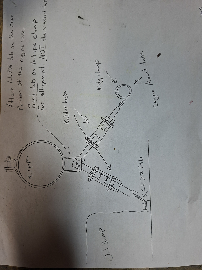
The image below is a picture from the instructions that come with the Vetterman exhaust.
After determining the best location on the passenger side, I installed both brackets in a similar way as pilot side. I did not use the same bolt on the engine case as the one near the corner was unreachable due to the engine mount.
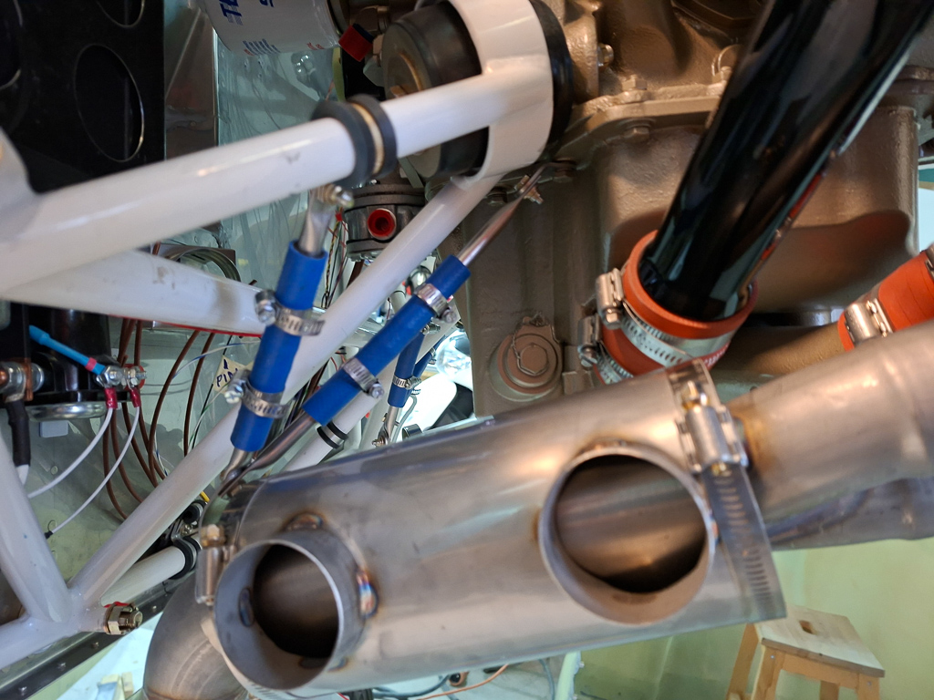
The exhaust clamp arm is also bent significantly more than on the other side.
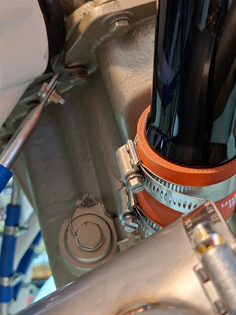
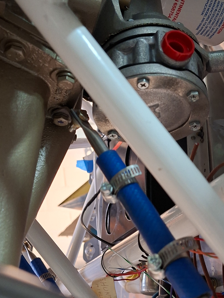
As you can see in the image below, the engine case bolt selected is just behind the corner from the oil sump behind the black induction pipe to the cylinder. It uses the 45° steel bend angle on the engine case bolt to set the angle for the hanger tube. You can slightly change the angle on this bended bracket to adjust for the right angle towards the exhaust pipe clamp.
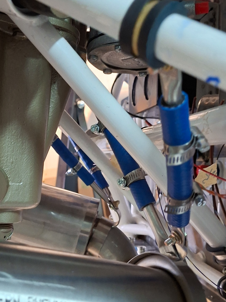
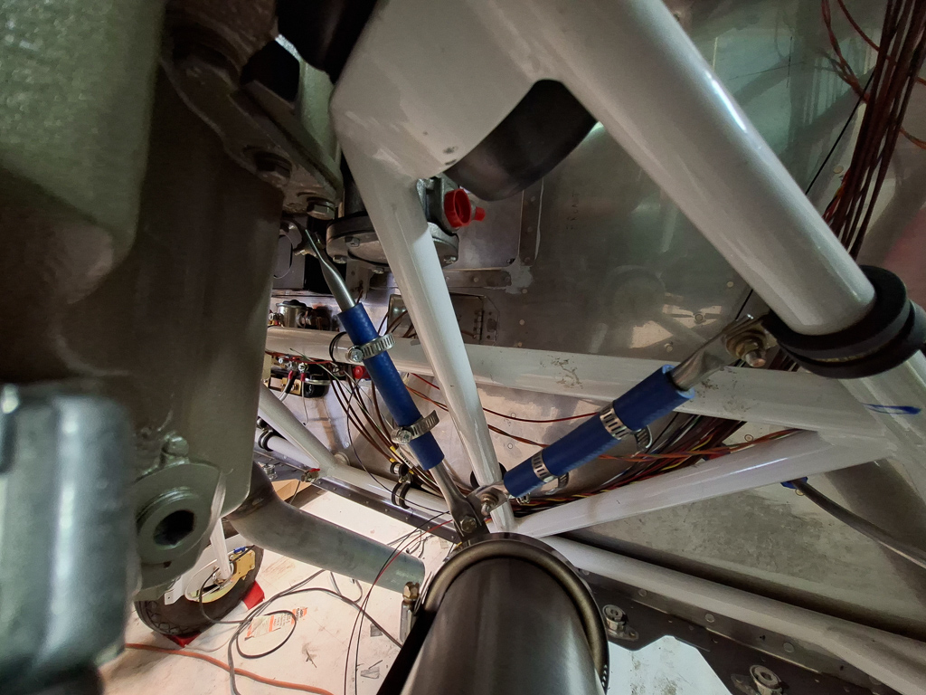
All installed with flared tubes and final hardware. Here is an overview of the support locations on both sides.
View from the pilot side. The hanger hanging from the engine mount is more or less in the middle of that engine mount leg and uses an additional angle bracket at the exhaust clamp.
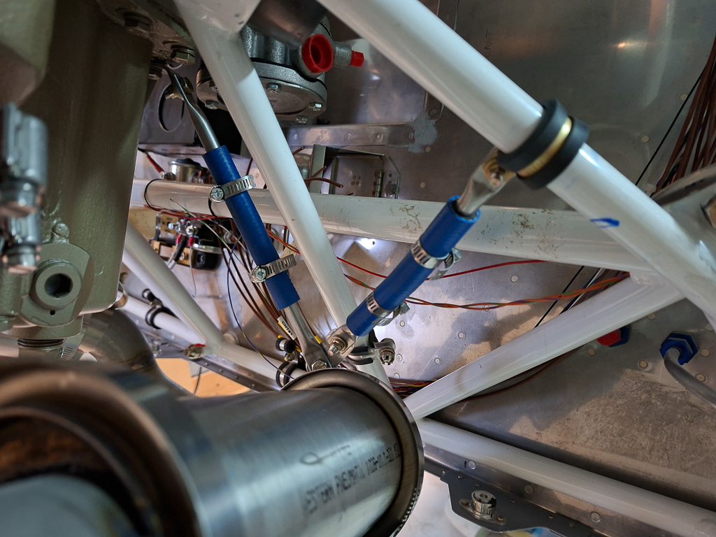
The additional bracket can be seen in this image attached underneath the tube moving towards the inside with the Vetterman steel bracket at 45° with only slight angle adjustment.
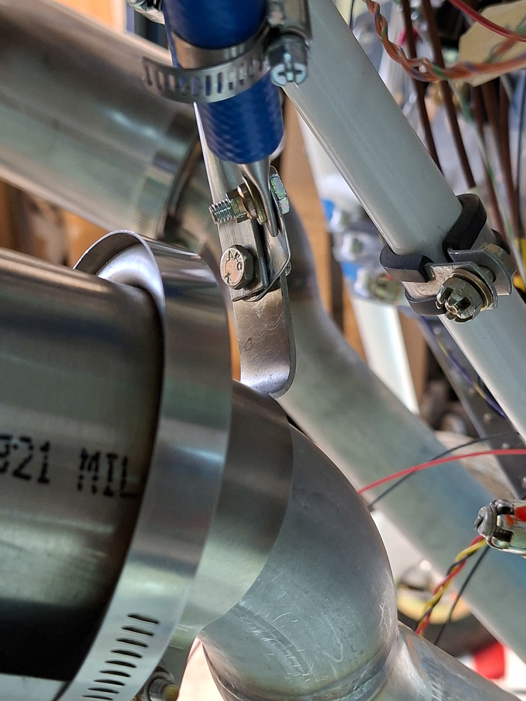
On the inner side, it attaches to the bolt in the corner behind the mechanical fuel pump.
View from the side showing both sides.
All this is unfortunately temporary as the exhaust will be disconnected again when the engine will be taken off for initial test run at the PMM Wingservice facilities.
So I didn't put the final torqueing on yet. Just tight enough to keep everything in it's final location so I can route all other lines for fuel, oil and electricity around it.