With the top cowling back line to fuselage skin line full defined and drilled with #30 cleco adapters, it's time to think about the final front side near the spinner again. In order to get a good match here, you may need to sand more on the top cowling horizontal split line in order to lower the front side of the top cowl. My bottom cowl is defined and it's is final position, now it's key to mate the front of the top cowl with the spinner, making sure it lays flat on the front split line of the bottom cowl. Sand those sides with a wood block to remain on a straight line towards the rear intersection line at the fuselage. That rear line is fixed now with rear top line being fastened.
I read on many builder blogs and VansAirforce that many builders take engine sag into account when mounting the cowling. Engine sag usually happens in the first 25 hours and can cause the entire engine (and as such also the spinner mounted on the crankshaft) by 1/8" to 1/4". The engine mounting rubbers holding the engine to the engine mount "set" with vibration in the first hours. This is always in the downwards direction off course meaning that the spinner height may move down in the first hours of operation. Most builders recommend 1/8" sag when using Lord mounts and 1/8" to 1/4" sag prevention with Barry style mounts. I have Barry mounts but am unsure about the amount to use. looking at 1/4" is already a big step down and if the engine doesn't sag as expected, it is a pretty high step between spinner and top cowling.
I decided to go with 1/8" step. It's the closest to what I already have now and only requires minor sanding on the horizontal sides. "IF" my engine would sag more than 1/8", the small extra step would be small. If I don't foresee anything and it moves down 1/4" the step would be considerable. So I'm going for the compromise solution and hope for the middle value of 1/8" which is what most builders do.
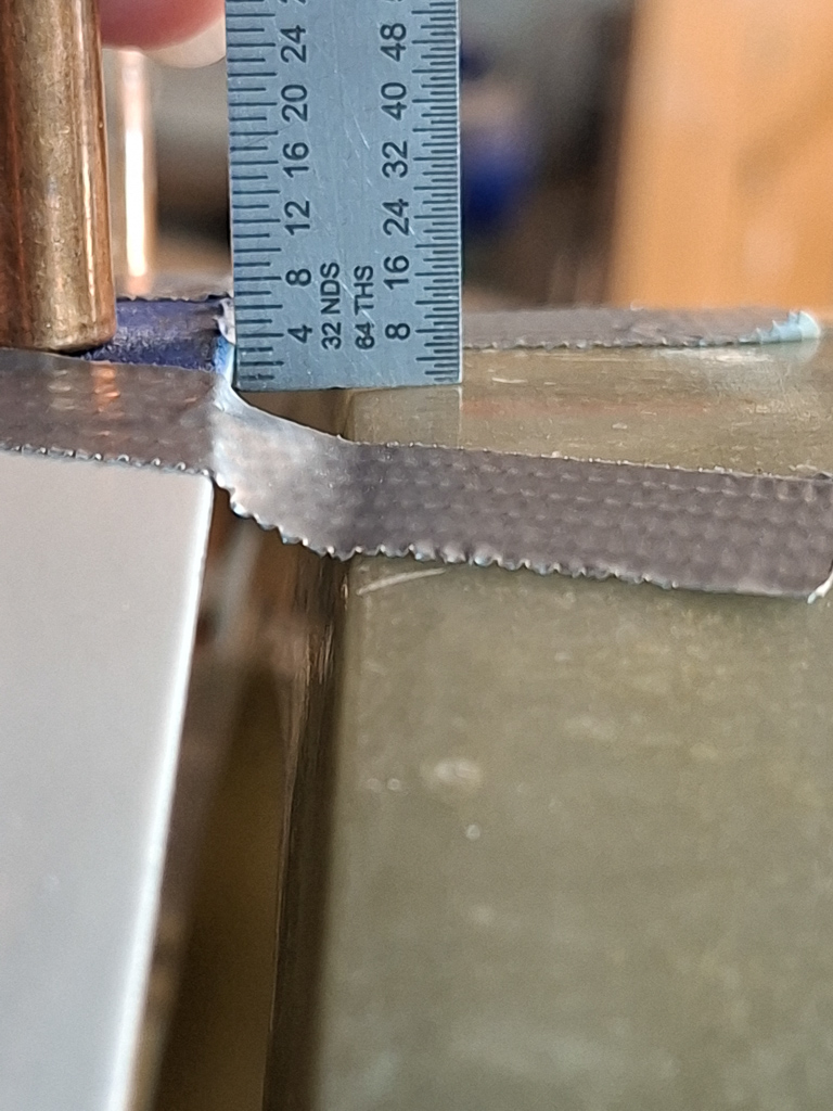
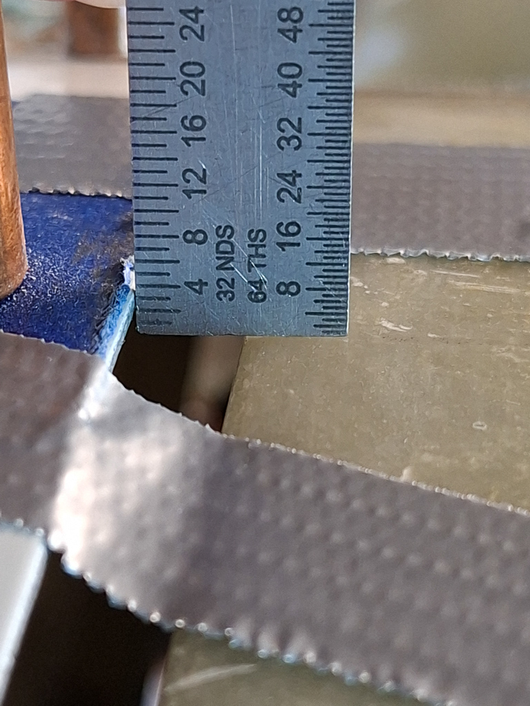
I took the steel ruler out and measured from the angled step on the front of the top cowl to the spinner and get to 4/32" or 1/8". Even if the hole things moves down a bit when attaching the final skybolt fasteners in the 15/32" holes on the side I still won't go over 1/4" so that's safe as well.
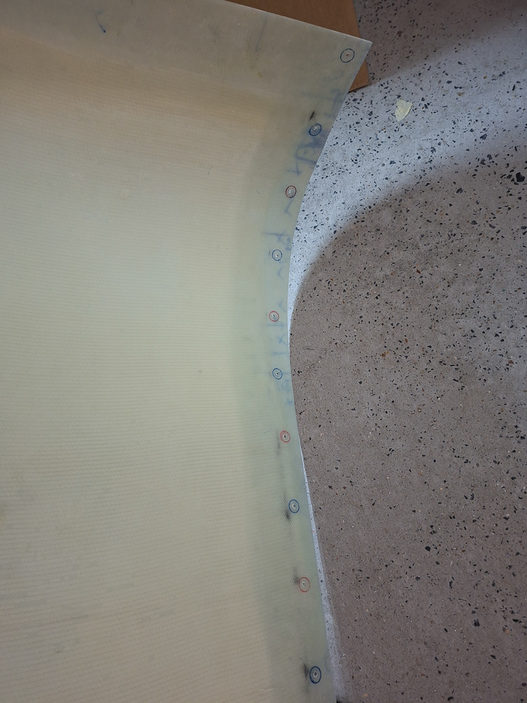
The image below is inverted, taken from the bottom up. What you see here are the traced holes in the top cowling read firewall line. I took out every other cleco adapter and took a sharpie to mark the location of the bracket holes. This will be the visual clues to updrill with a unibit #1 up to 15/32", making sure the hole stays centered in the marked circle. Moving the hole slightly using a unibit in epoxy is fairly easy and there are multiple steps down the road up to 15/32". This updrilling seemed critical and difficult but it was actually a walk in the parc
Then placed the adapters back in the just traced holes, clecoed and did the same on the newly freed hole locations.
After taking the top cowling off, you now have all drill traces.
I am quite unhappy of the shape of the cowl on the passenger side near the down-bend line. This is the location where the cowling is extra reinforced because of the oil door location. In this 7 to 8 inch, the epoxy is much thicker and was sticking up over the fuselage skin. I decided to place an additional 0.032 shim underneath this length which is about 10" in total.
This will lower the top cowl enough to be level with the fuselage skin.
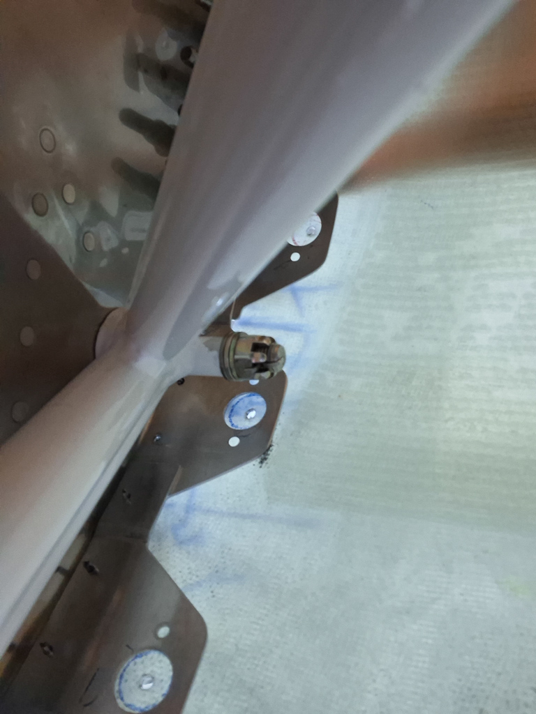
Created a strip of 0.032" stock alu and used cleco clamps to position it under the already present 0.032" shim. So in that location, the total shim height is 0.064"
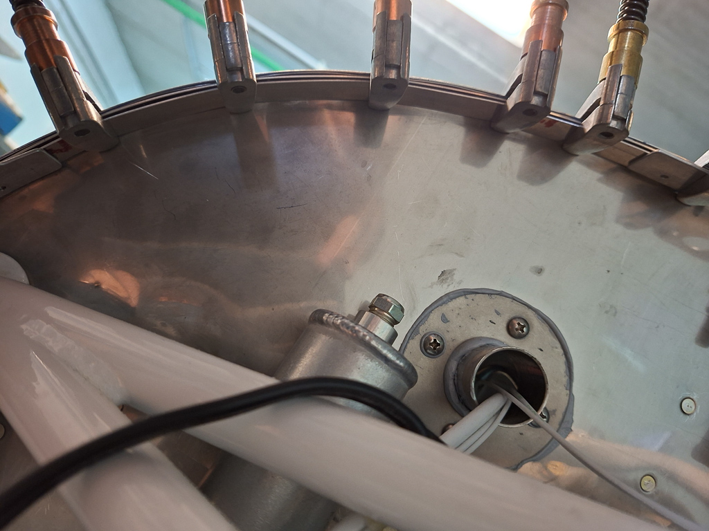
View from below showing the extra shim strip.
With the skin, firewall and already present shim as a guide, I matchdrilled the holes in the extra shim.
After reinstalling the brackets, the fit was near perfect. Glad I took the time to get this right. I did have to retrace the circles on the lower holes as this extra shimming did move all holes down the road down a bit. Not much, but enough to get alignment problems later on if I didn't pay attention to it now.
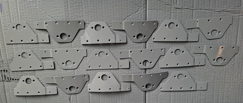
Then I took off all brackets and primed them. I am using a spray can primer in gray and sprayed 8 layers of primer paint on the brackets.
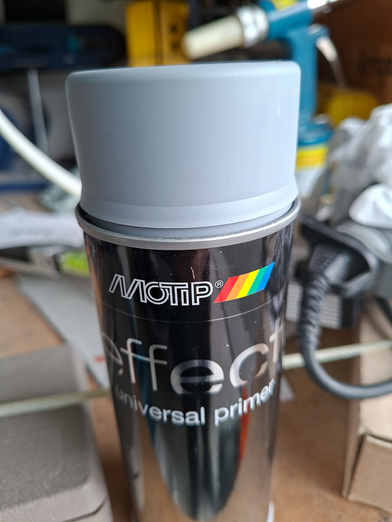
The primer is a good choice. It dries pretty quickly and after 4 hours of waiting I could invert the parts and also spray the back side on the same day.
Make sure you number your brackets and then lay them in an organized way on the paint table. All these bracket and shims form a complicated puzzle if you loose track of who is who.
Once primed, write the number back on the bracket on a side that will no longer be exposed after riveting.
Priming done.