
Finally a feel good day again in the shop. After many days of trimming and sanding, I was able to fixate the top cowling top line to the firewall.
I started the day with more trimming and fitting. following my classic technique of marking with a sharpie pen and sanding it down. The edge in the bend came out ok and I also trimmed down the vertical line.
This gap is still too tight for painting but I'm planning to remove the extra 0.020" for painting only at the last moment. I prefer things to be snug for now so that I just have to sand down a little more without the risk of creating oversized gaps.
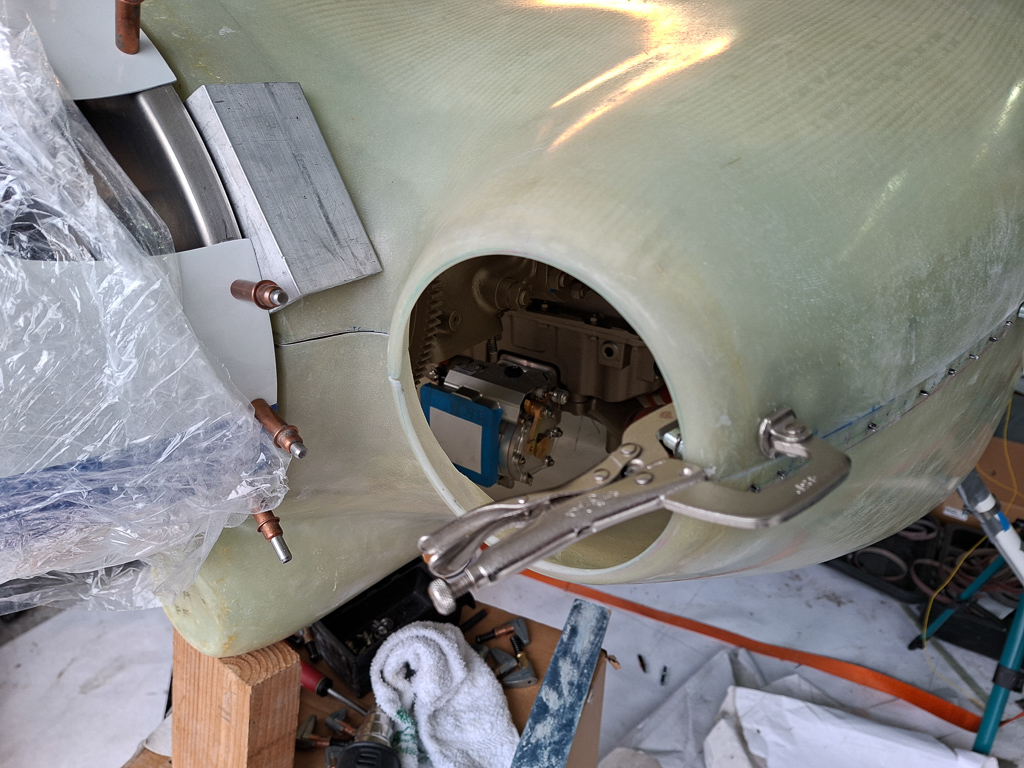
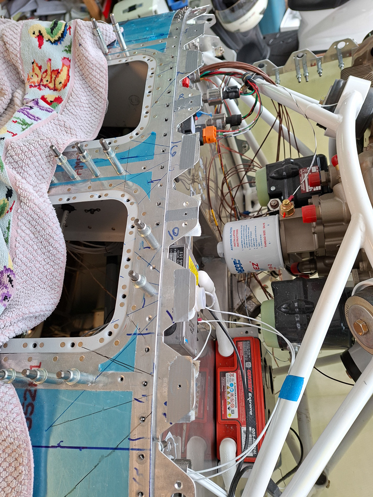
With the side line also at final size, I was able to use a clamp to fixate the position of the upper and lower cowling at the air inlet side. The stock angle defines the gap at the spinner as shown in the image below. I'm less worried about the fit in the center transition. This can be adjusted and worked on later on. There will be an epoxy layer added behind the bottom cowl which will hold a nutplate that ties the top and bottom together with a screw.
Also clamped the passenger side
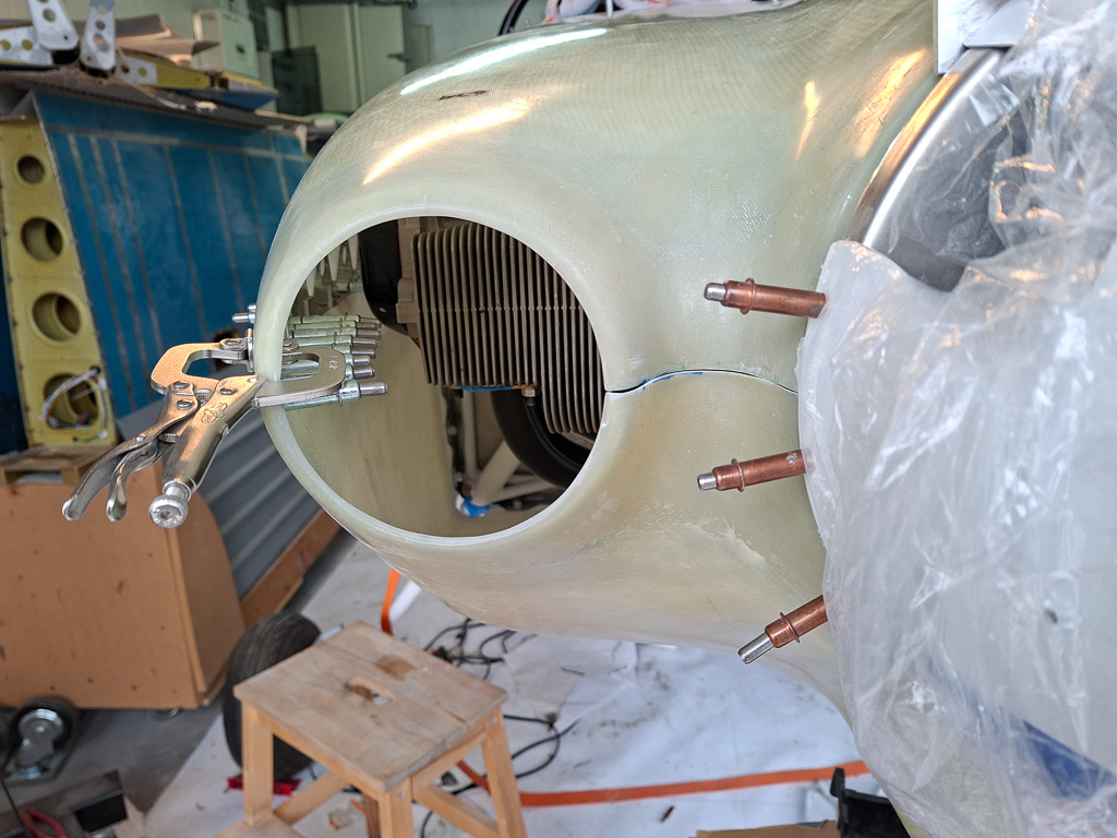
Rechecked the fit on the passenger side. looking good.
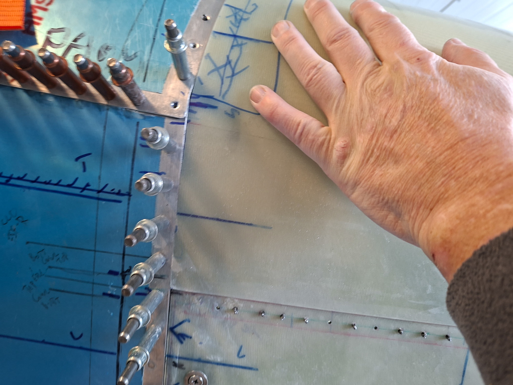
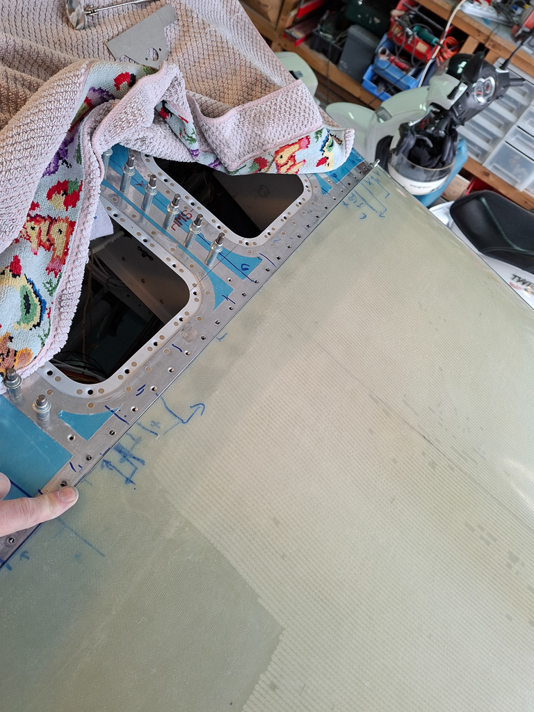
The top line sits snug and lays flat on the flanges with little or no gap.
All lights on green to start drilling the first holes.
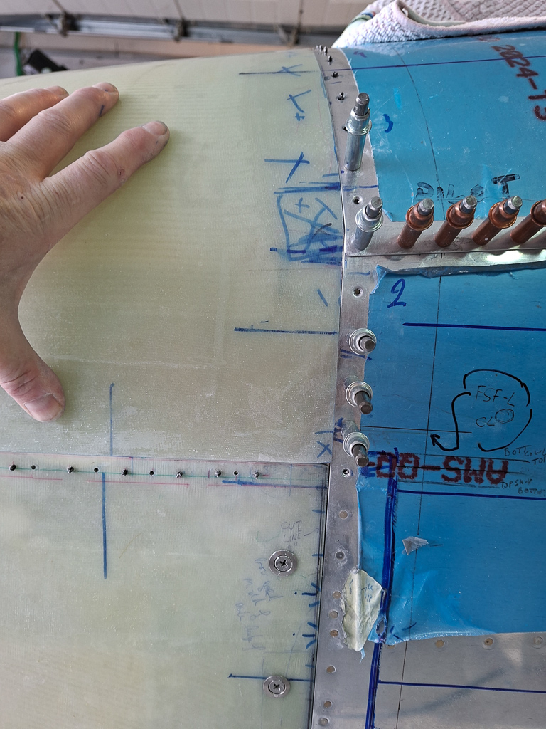
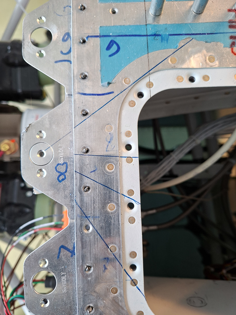
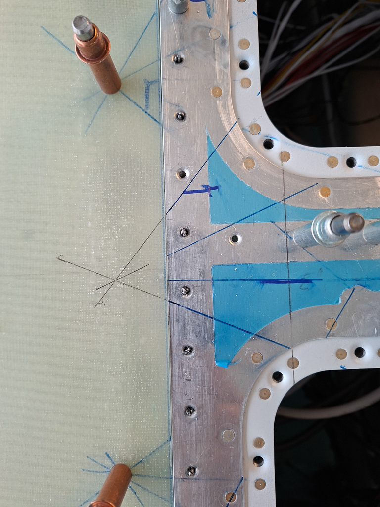
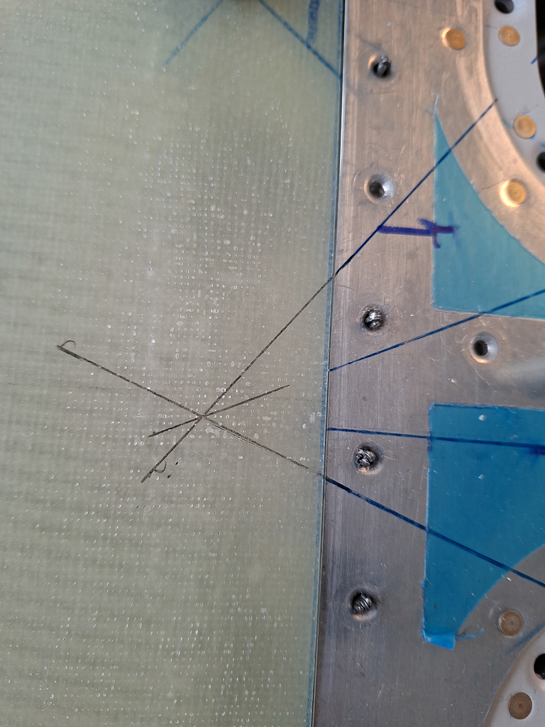
The next problem is that you have no idea where to drill... as the top cowling lays on top of the bottom, there is no way you can trace a hole or make markings. The only solution I came up with was to install the cleco adapter in the flange and draw intersecting reference lines on the fuselage which all center in the center of the hole of the cleco adapter as shown in image below. 2 lines is sufficient but I want to be precise and made 4 lines to increase the precision.
Then I used duct-tape to tape the cleco adapters in the holes of the flanges. That's the only way you can keep them in place while drilling blindly through the top cowl.
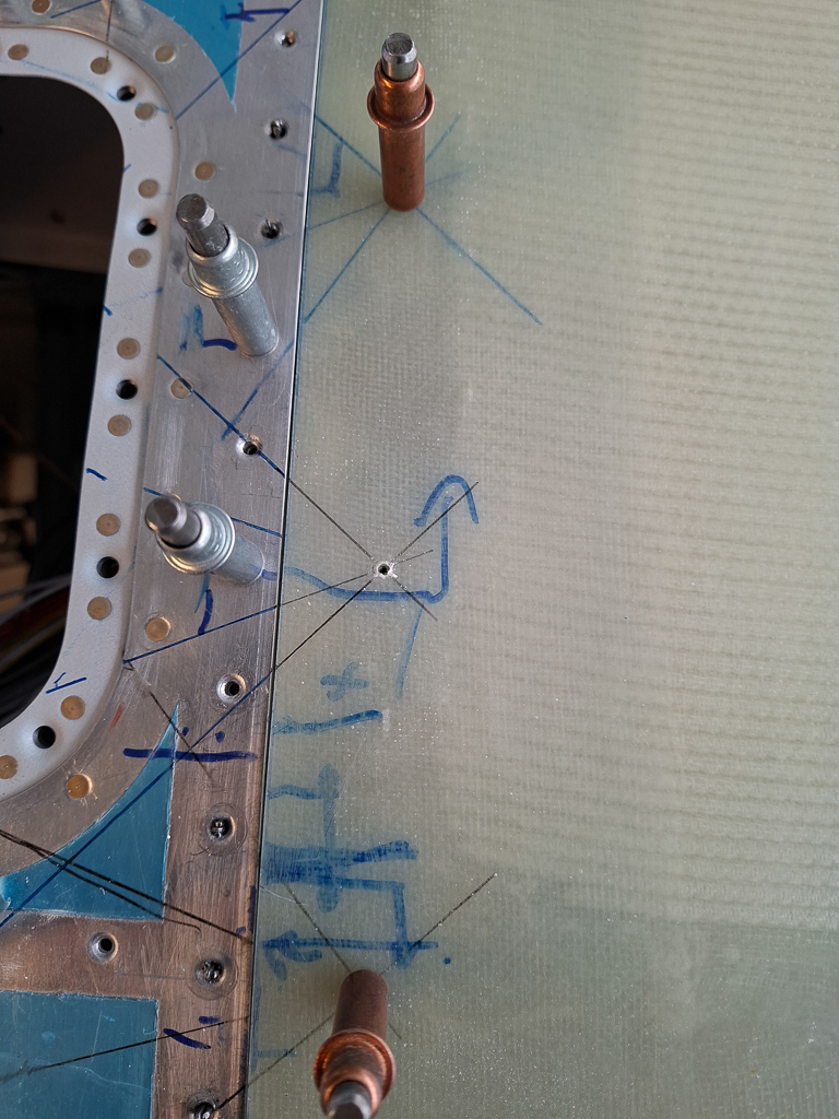
And below you see the result. Lines extended back from the fuselage reference lines and drilled first #45, #40 and then #30.
An easy and precise technique that worked really well. All holes were dead center and as you can see by my line between cowl and fuselage skin: it's still dead on.
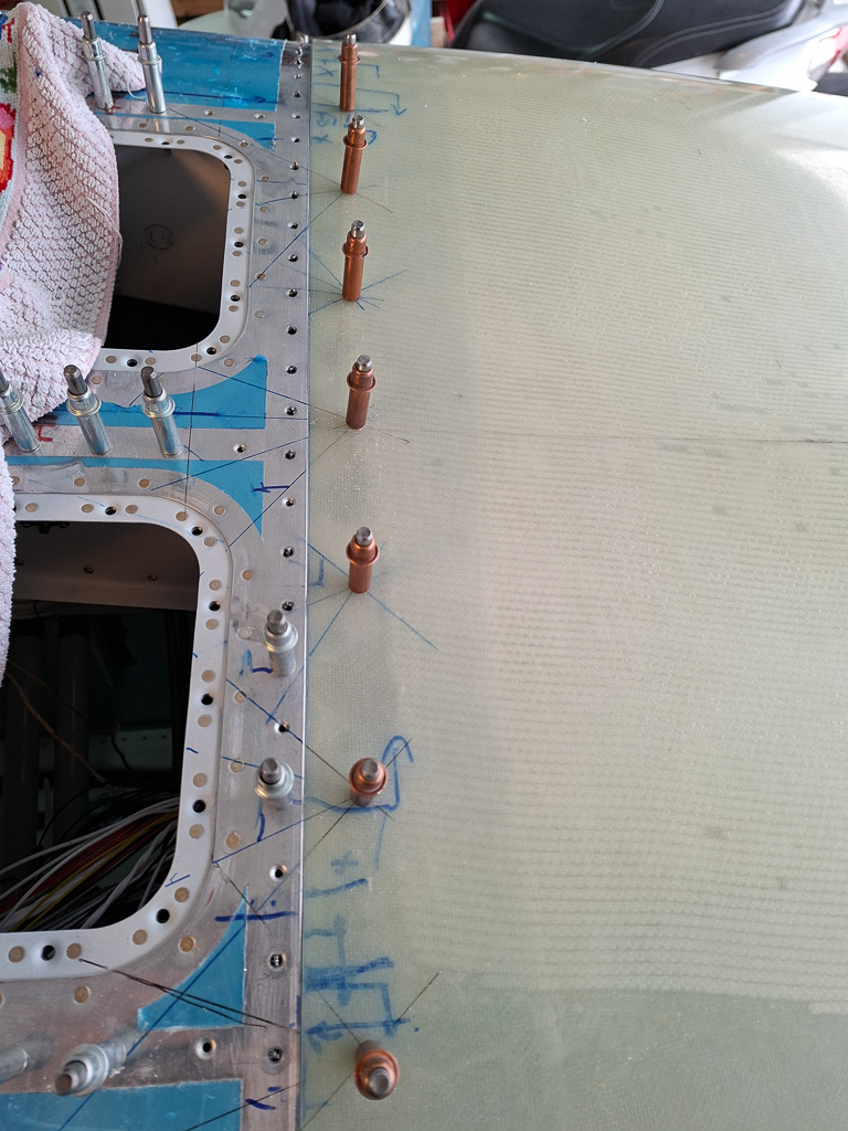
I started drilling on the center line of the airplane and move down alternating left and right, each time pressing down on the cowl while drilling so that the cowl fits snug with the fuselage skin.
Another hole drilled
Time was up for the day but I'm very pleased with the result, I made it up to the fuselage bending at the sides. Next time I will drill all the way down and evaluate the horizontal trim line again before also drilling those holes using the same technique. Unfortunately, there are not enough cleco adapters in the kit to do all the fasteners so I might have to prime the flanges first, install the final receptacles and use the skybolt studs in the top line so that the cleco adapters can be used again on the sides.
This brings up another question. How to define the holes for drilling up to 15/32" for the final size. My thinking here is to remove the bottom cowl and hang the top cowl by the adapters once the side are also drilled. Then remove a single adapter, trace the hole in the flange on the cowling, reinstall the adapter and do the same thing on the other ones. That way, the top cowl is in it's fixed location and each hole gets traced with a sharpie pen. Then I can remove the top cowl and enlarge the holes with a unibit just like I did on the bottom cowling.
sounds like a plan!
I took some moments admiring the beauty of it and look forward to the next work session.