
I already made the attachment angles for the deutsch connectors so now was a good time to do the wiring of the nav and landing light wiring on the male side of the connectors. These have male or pin connections. The part coming from the wing is the female connector and has female sockets
In an earlier article, I described how you use the shield of the multiconductor wire as GND wire behind the instrument panel on the cockpit side.
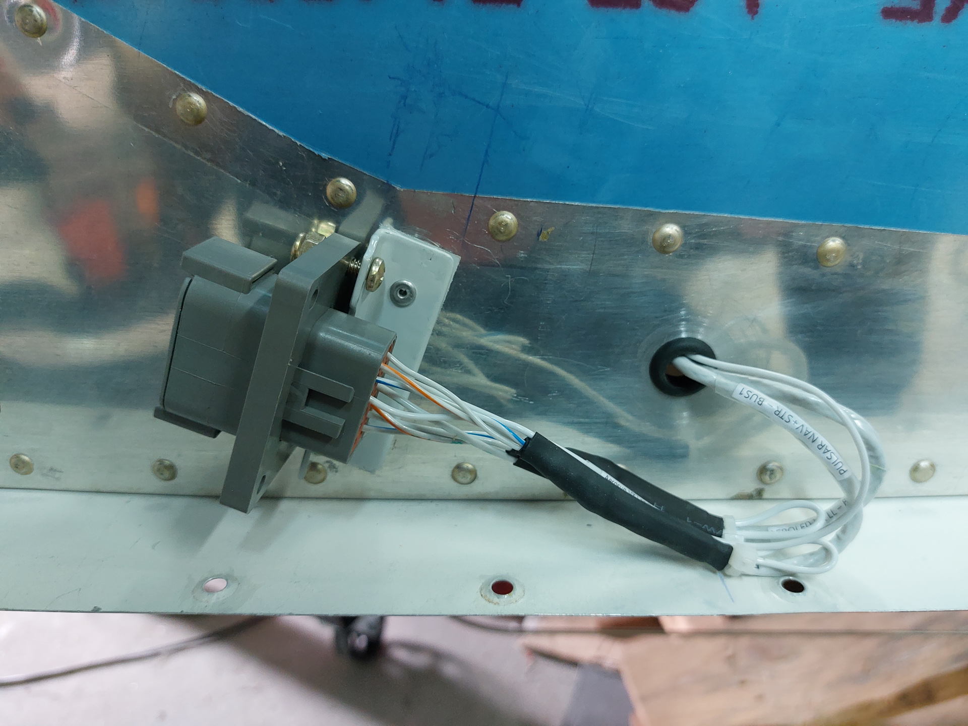
As I am disconnecting the wire at the wing root, I also have to pass the shield signal through the connector. So the same procedure of using soldersleeve and adding a gnd wire is applied here at the connector side to allow passing GND through one of the pins (and through the shield) of the 2 connecting wires.
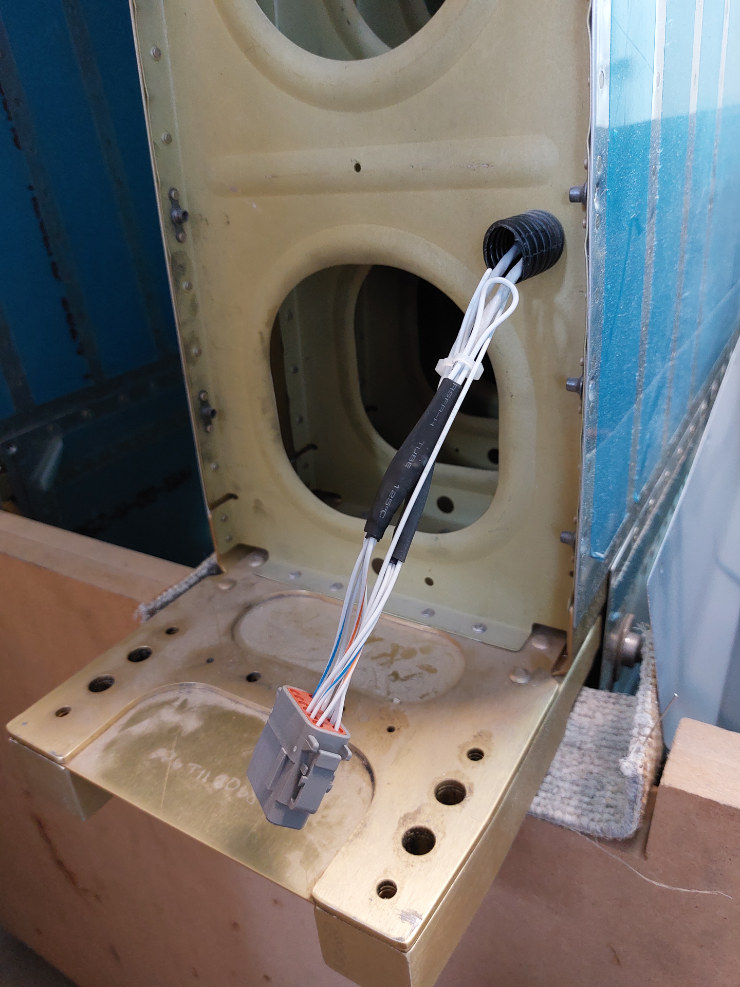
In the image below, the nav multiconductor shielded wire and landing light shielded wire are prepared and covered with heat shrink. I installed all pins in the connector and temporarily installed the connector to check. I will probably still attach and adel clamp to keep the rear of the wires in the bend close to the outer fuselage. The space between the wing and fuselage is really narrow there and the wire won't probably run nowhere, but I don't like the idea of loose wires or chafing wires as subject to vibration.
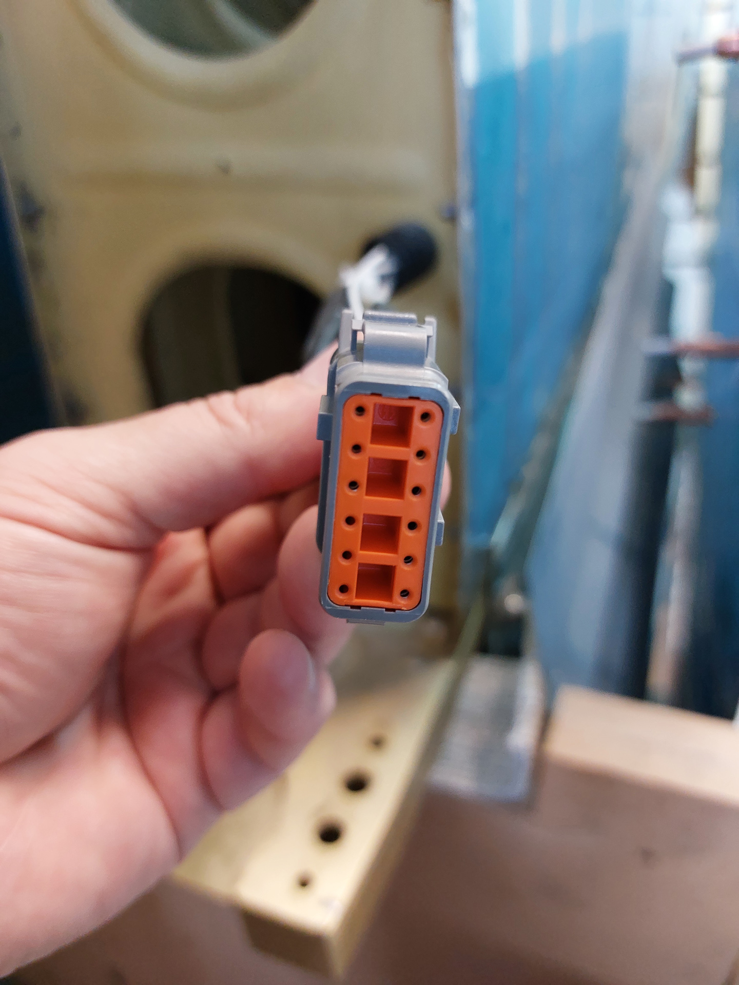
Forward view with the pins inserted. There is another plastic insertable lock cover that keeps the pins in place
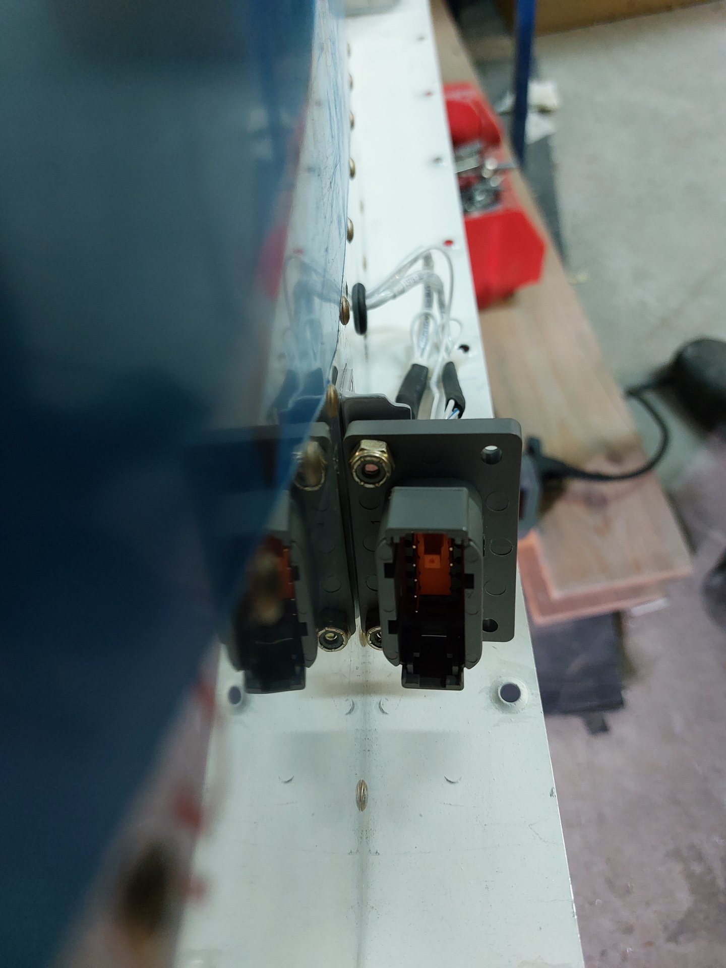
Same work completed on the passenger side. On this side there will be an additional connector on top of this one for the Dynon autopilot wiring harnass.
One pin less on this one, the other one also carries the stall warner signal.
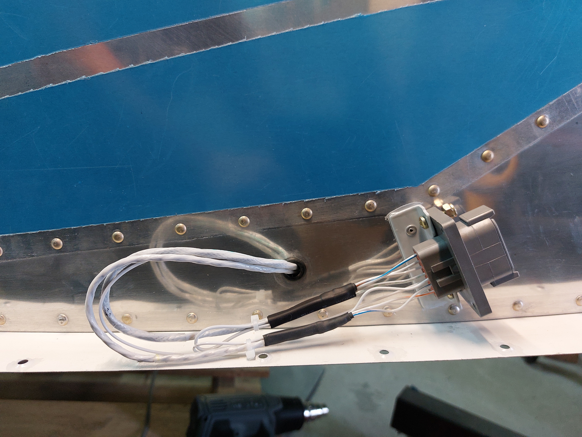
Next I prepared the wires on the wing side. The idea here is the same but on the female connector and with female pins. Just need to keep your head around making sure you match up the right colors in the right positions. It's always good to keep a connector schema in your documentation that descibes pin numbers and functions.
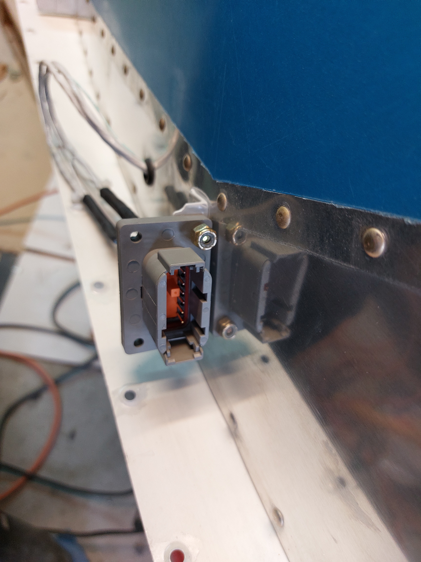
This is the female connector with the plastic protection cover over the pins already inserted.
On the rear side, you can install small pins in the outer plastic to cover in order to seal out moisture from the pin positions that are unused..
as a final task today, I pulled the 20 AWG wire for syncing the landinglights through the fuselage. The wire connects both landing lights, splits through the connectors and runs via the F704 bulkhead to the other side of the fuselage.