

I always thought the fear fairings and leg pants were the last thing I would ever to on the airplane before final assembly. As the engine is still not ready, I can't start the firewall forward work and am trying to find other tasks to complete in the long wait. I'm running out of electrical system work as well so decided to go for the gear fairings next. I always though this would be a walk in the park but after reading the manual and seeing some video's from other builders, as usual thing look simpler then they are in reality. The manual is very vague when it comes to installation of these and the plans look like a mystery when you first look at them. I found the video's from Karetaker Aero very usefull to get an intial idea about the steps involved in the process. Once you've seen those and revisit the manual, things become a lot clearer.
I hadn't thought of it before, but the manual clearly states how critical the installation of the gear leg fairings is. If not properly aligned, a difference of 1/4 inch can cause serious slip of the skid ball in straight and level flight which requires significant rudder input. I will try to write down and illustrate my process in detail in future articles.
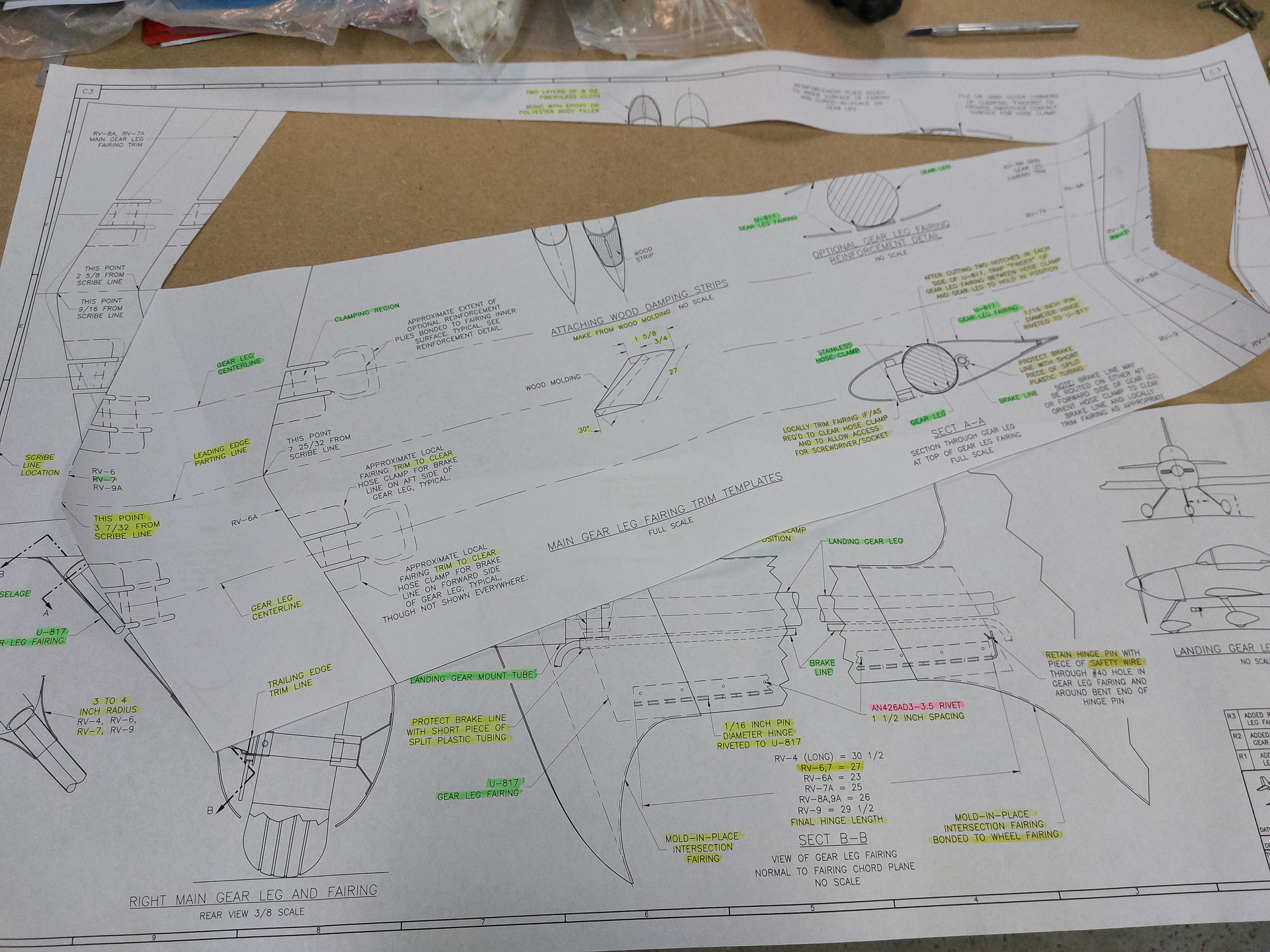
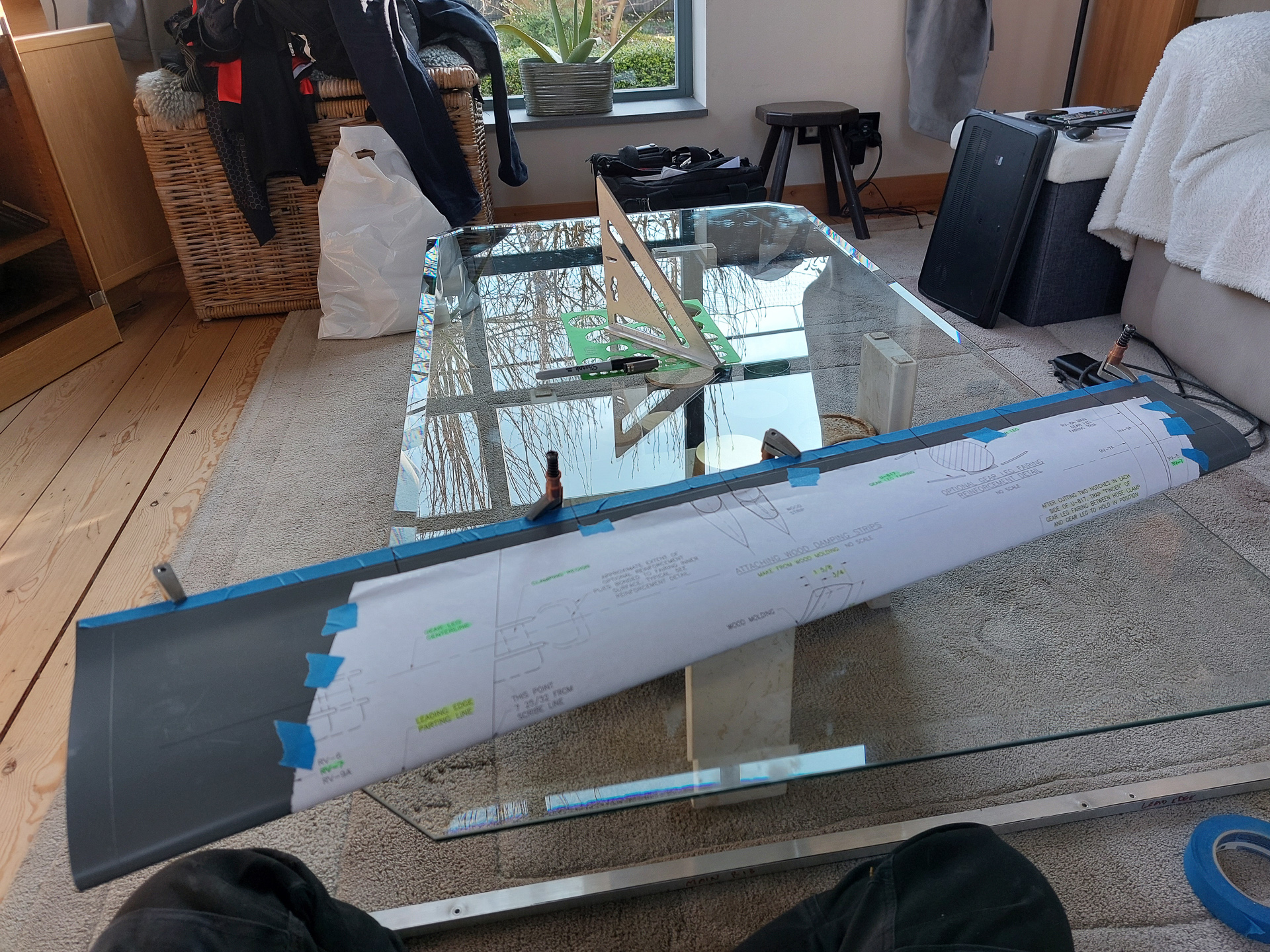
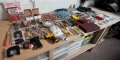
First thing I did was cut out the template from the plan. It feels bad having to cut up an original plan but I have to way to copy such a large paper so decided to go ahead that use a cutter to cut nicely across all the lines. There are multiple dimensions for multiple type RV's so make sure you cut along the right lines up and down. The size at the bottom is very liberal and you will have to further trim it down but you should only do this from the bottom (the narrow side). The top side is the exact size of the line on the left side of the plan.
Here you see the cutout of the template on the RV7 lines.
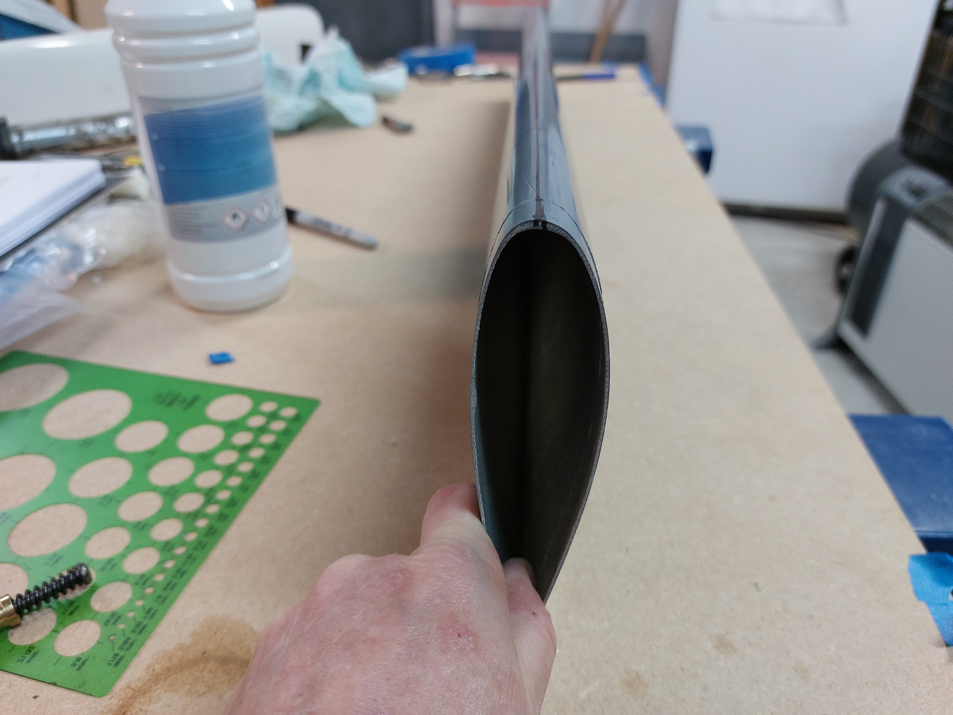
Next you first need to determine if there isn't any twist in the moulding of the fairing. This is a bit tricky and is best done with 2 persons as you will get short of hands to keep things in position and measure at the same time. Mark the center line location on the edge of the fairing on the leading edge. This is a bit tricky as the shape of the gear leg is not exactly symmetrical and it's a bit of guessing to find the exact center point.
Put the fairing on a "sure flat" surface with the leading edge on the table and the trailing edge sticking up in the air. Place a square on the surface of the table and align the bottom of the square with the center point and move the top of the trailing edge to it aligns with the top of the square. On the other side of the fairing, have a second person hold a square on the center line at the leading edge and have him verify that the trailing edge also aligns with the top of his square. It's best if he moves the fairing around and the other one verifies if his line still matches. The trailing edges should both be vertical above the center line at the leading edge. This ensures there is not twist in the trailing edge. Tape the trailing edge to keep it in position. There was some tweaking required on mine and you can't just rely and aligning the epoxy on the trailing edge. The manual tells you to draw lines and cut the trailing edge again. I did not do this and kept it taped firmly to ensure nothing would move.
Next you tape the template on the wheel fairing. The template had you tape the front of the paper at a defined distance from the scribe mark on the fairing. Make sure to follow this as it defines the bulge in the fairing is equal on both sides. Get the paper flat on the fairing as good as you can and tape it down.
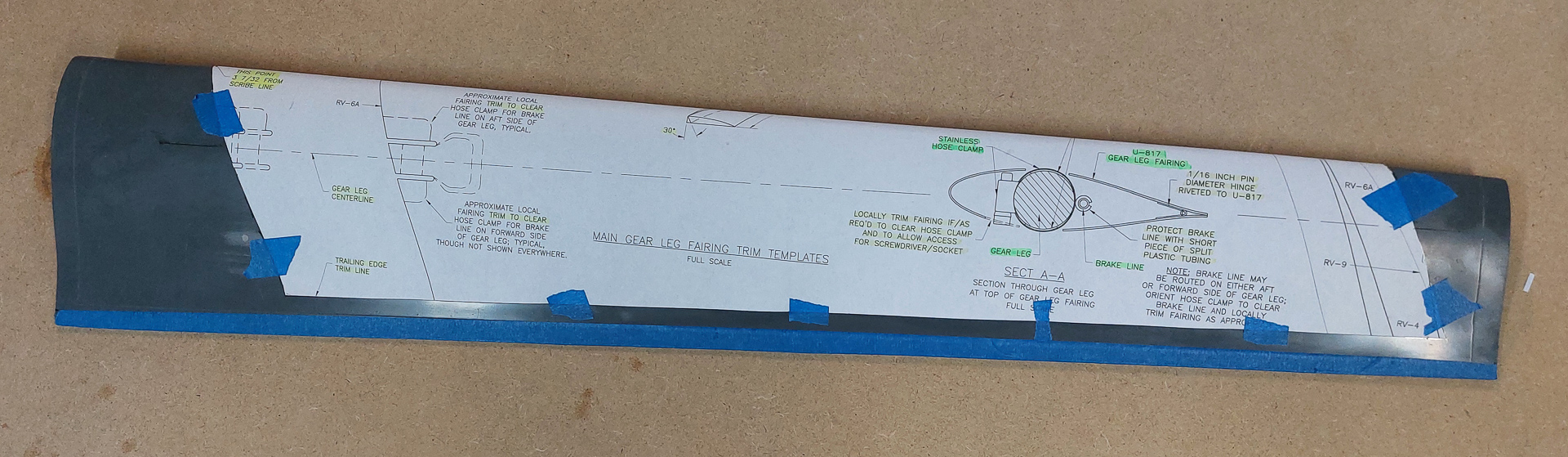
Next use a sharpie to mark locations from the template at the edges and also mark the center line on the template on both sides. This helps later to align the fairing on the gear leg.
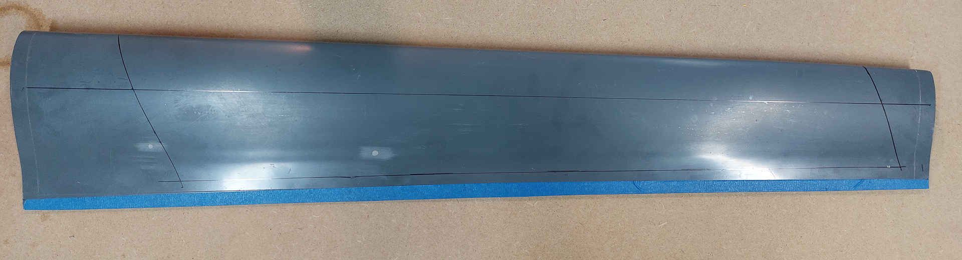
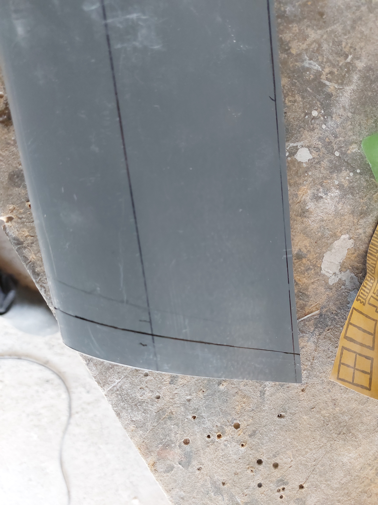
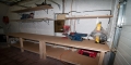
In the image below you can clearly see the "scribe" line on the right. This one is on the bottom but there is another one at the top and that's the reference point for measuring the distance for the template.
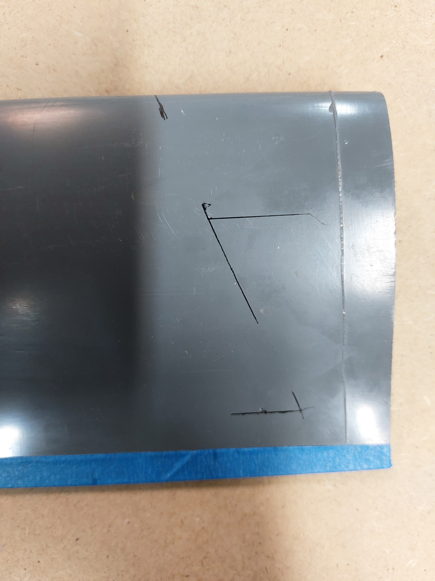
Connect the markings and you have the cutout form.
Next i marked the centerline on the hinges. After drilling the initial holes in the fairing, you can align the hinge so that you can see this line through the holes and ensure you drill in the center.
Drawing the centerline on the top of the fairing is a bit more difficult. It's eye-balling and the shape of the premade fairing is not exactly symmetrical. I gave it my best shot to place the centerline on top of the leading edge.
All marked and ready to start cutting. I used the cutting disc used for the canopy cuts. The manual tells you not to cut the trailing edge. Only the sides.
I did not do that and had already cut the rear side near the line. If I would have to do it over again, I'll leave it on. Just believe what's in the manual, they know better than we do at Vans.
With the top and bottom cut, I gave it a test fit on the leg in order to determine the exact length. The manual states that the template is liberal and it is indeed. I cut off a fair bit. Just make sure you cut from the bottom of the leg.
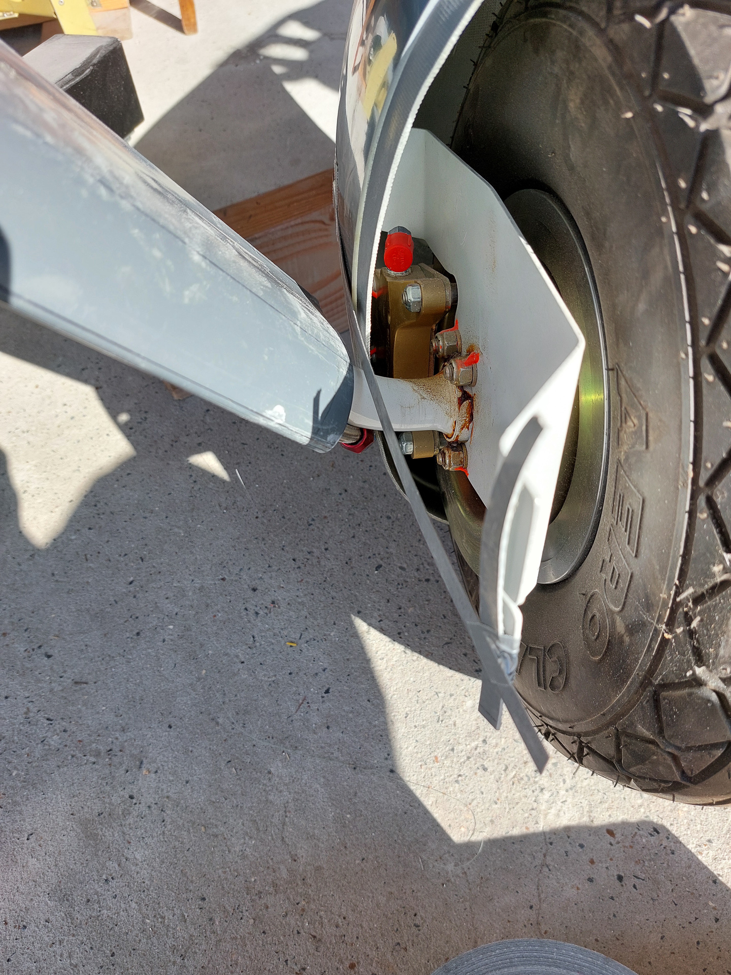
How to know the length ? Good question. I came up with this idea to make sure I could install the leg fairing after the wheel pants are on.
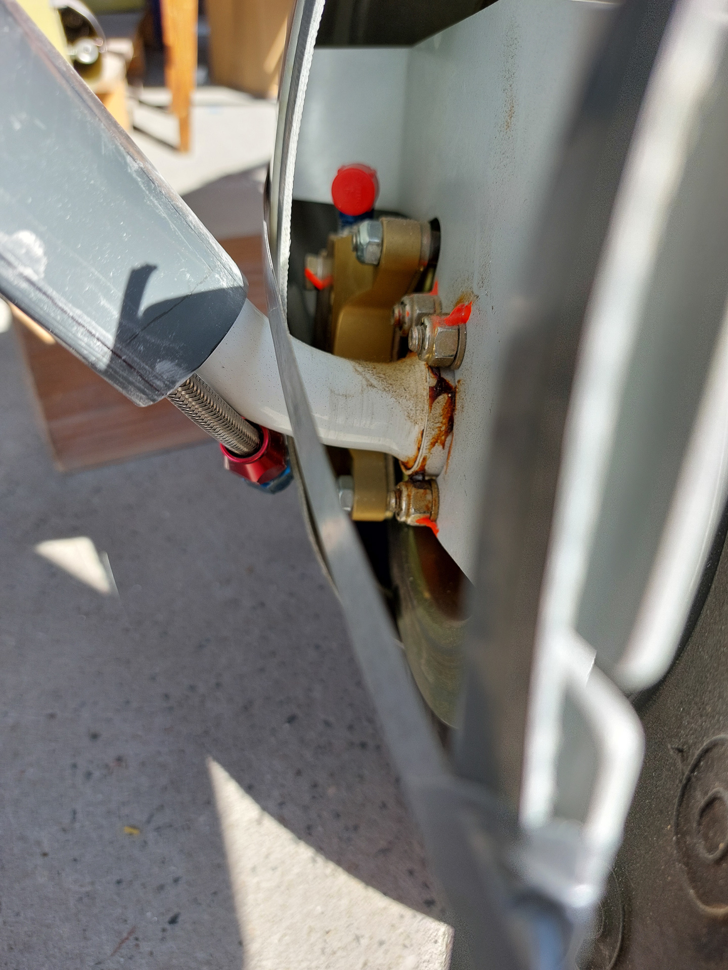
Placed the rear cone approximatly where it's supposed to come. Put the 1 inch spacer over the tyre and made a wild guess where the wheel pants would end up on the side bracket. As you see image below, the intial cut is indeed way too long.
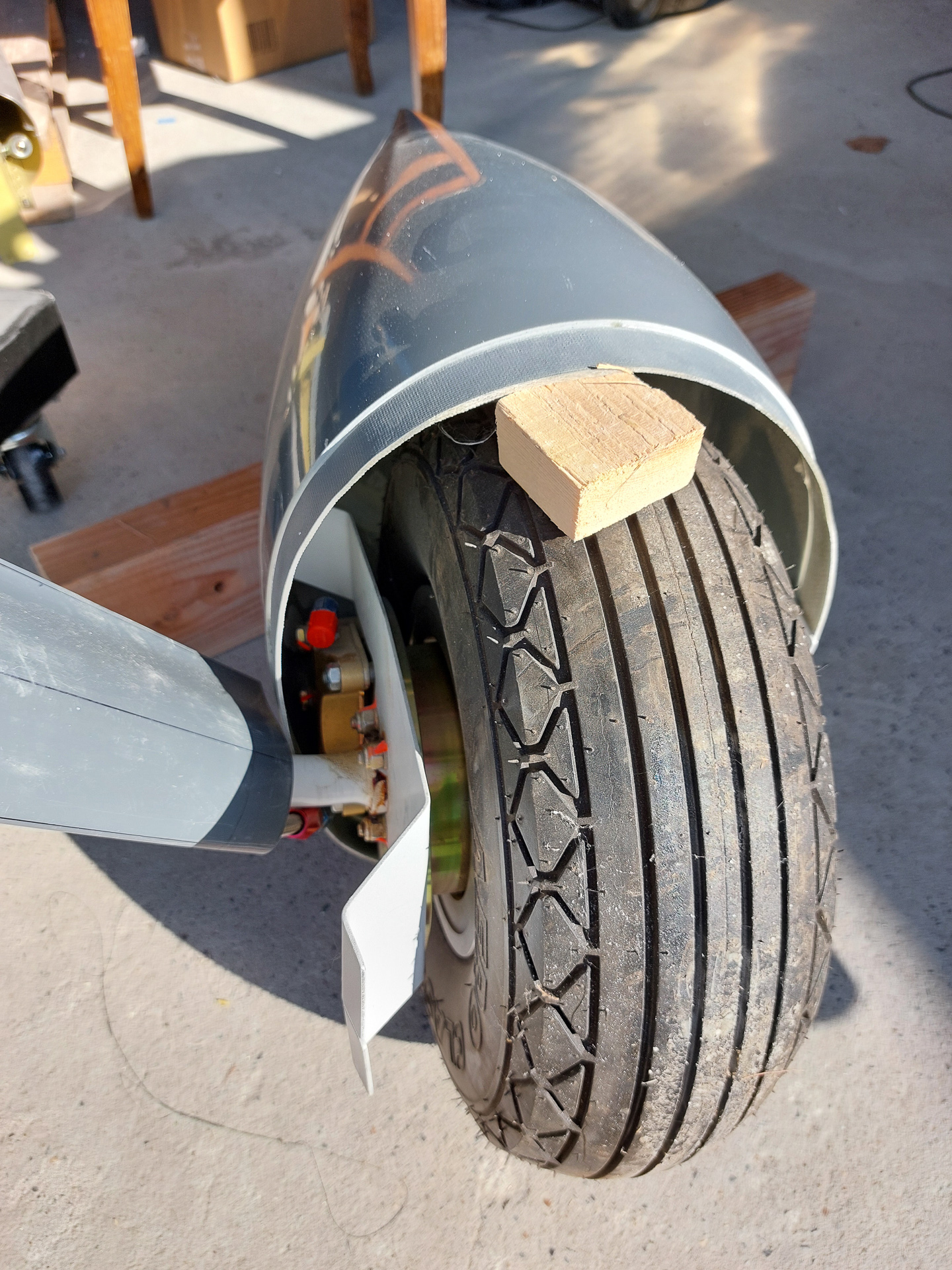
I had to cut of close to 3/4 inch in order to get it to fit.
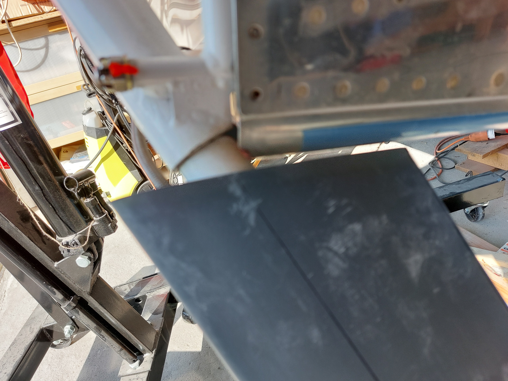
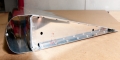
After cutting, I reinstalled the leg and tested the bottom in alignment with the wheel pants. My flexible ruler served as artifical front side of the cone.
I made the ruler follow the contour and it looked like I got sufficient space with a little bit of playroom on both ends up and down. The intersection fairing will cover all of this. I have ordered them as aftermarket parts but I haven't received them yet so I don't really know how long they are.
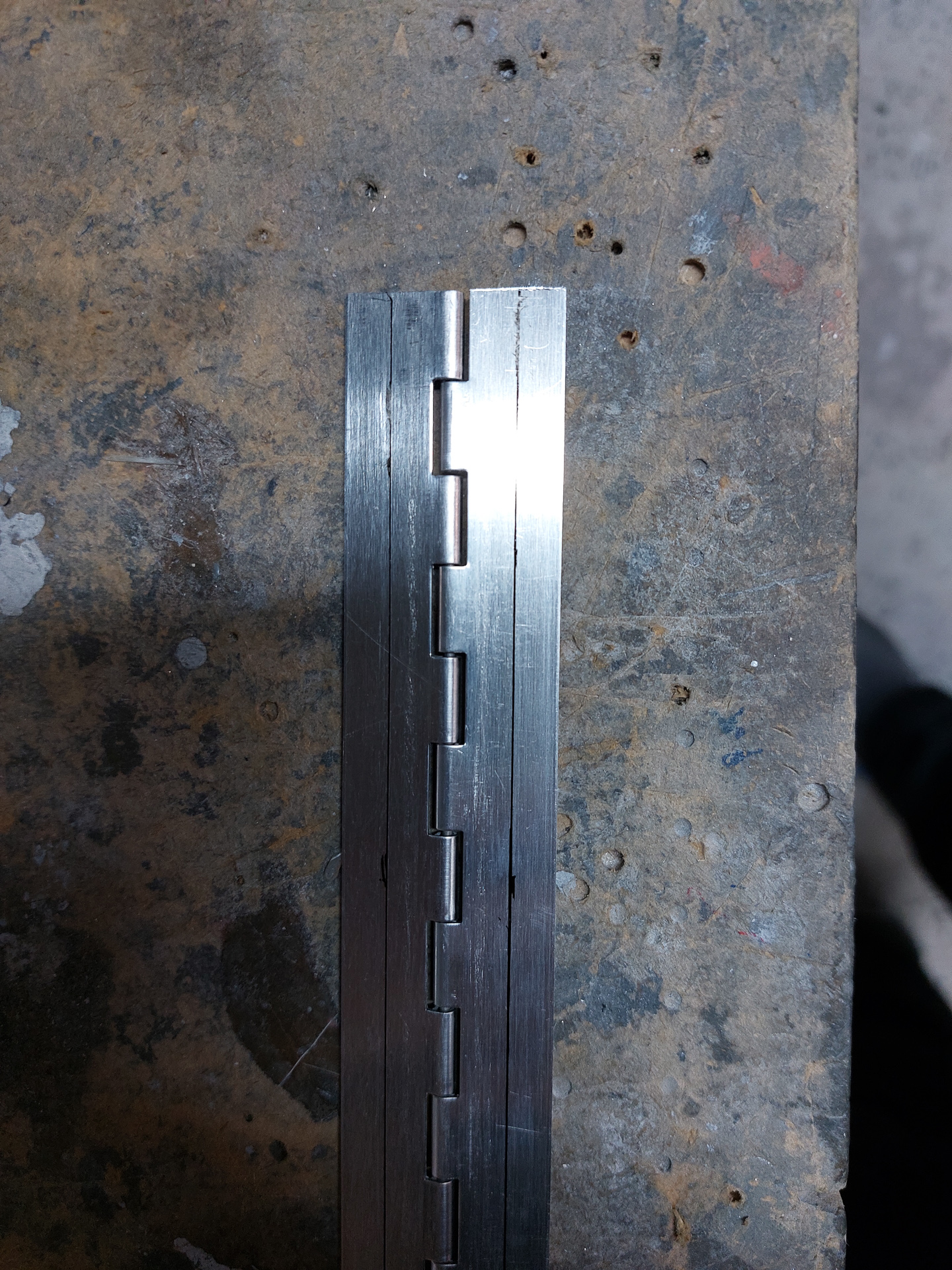
Then I positioned one side of the hinge in the closed trailing edge of the fairing. Checked a couple of times on both sides and transferred the middle line marking on the fairing.
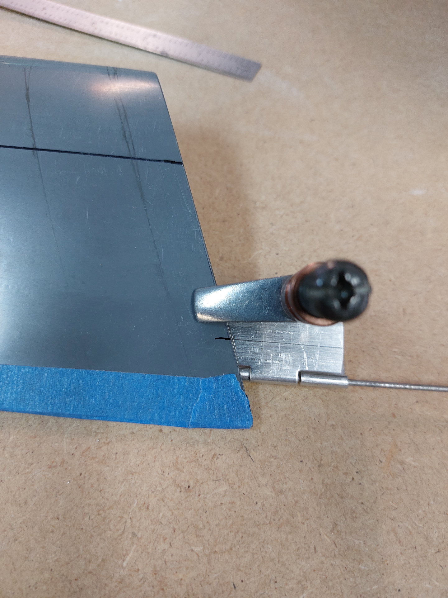
Your initial mark should be with the hinge nicely touching both sides of the fairing without stress pulling in or pushing out.
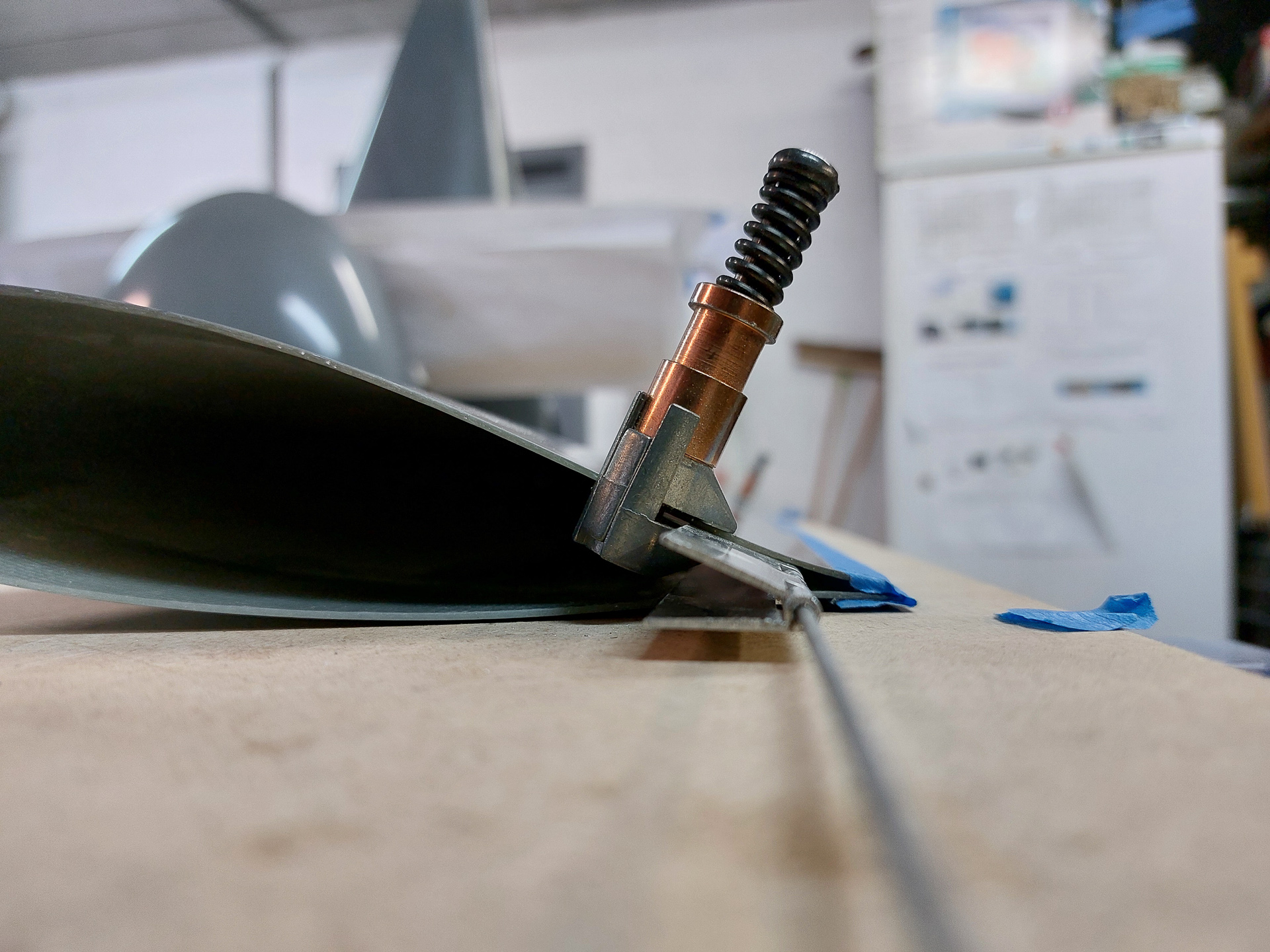
Then I also marked the other side and connected te dots with a rivet line.
Next, I moved up the mark towards the front, a little less than 1/8". This will require the center of the hing to be pushed a bit in order to insert the pin. The pushing of the rear side will pull the 2 trailing edges together. The trailing edge still needs to be sanded towards the final line. Bringing the hinge a bit forward will increase the "pull together" tension on the trailing edge but you don't want to get it so far that the trailing edge start pulling outwards. Just a healthy bit of pressure is enough and will ensure that you don't have an open gap once you start sanding the trailing edge back to the line.
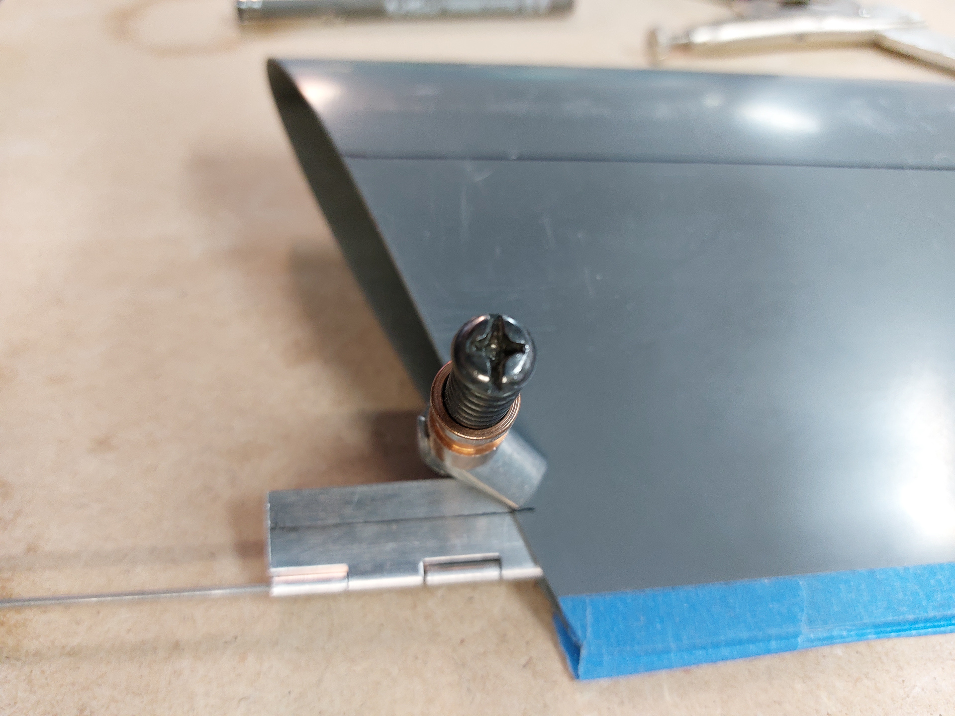
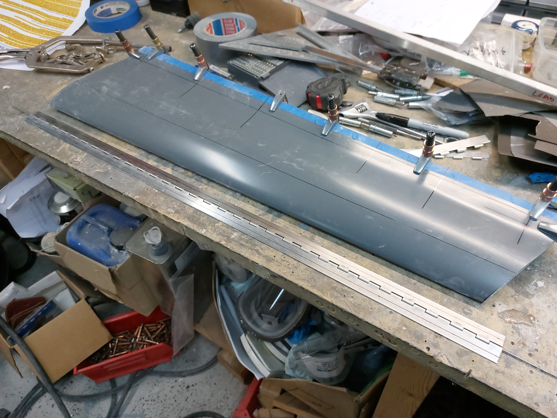
In the image below, you can see the original mark using the hinge left and right underneath the drilled line.
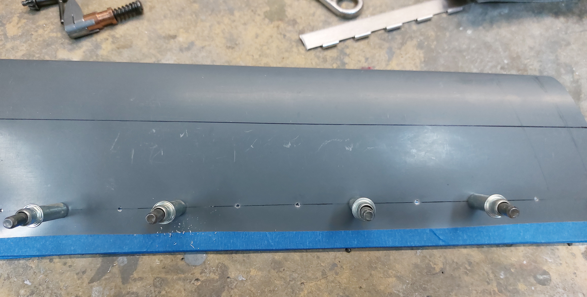
Next steps is laying out the holes. Mine are about 1.4" apart. Drilled all the holes #43. A bit undersize so I can final ream them later on.
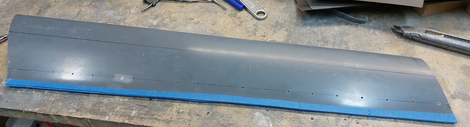
After drilling all the holes I reclamped one side of the hinge and ensured the centerline on the hinge was visible through the drilled holes.
The manual wants you to drill these holes while the fairing is attached to the leg. I see no good reason to go through that hassle. Having the fairing on a flat surface and drilling the holes through the pilot holes in the fairing works just as good. The whole idea is not to introduce any twist so make sure the trailing edge is laying flat. Started drilling the holes. First the two outer ones to make sure the hinge stays in the right position. Then the center one and gradually filling up the rest.
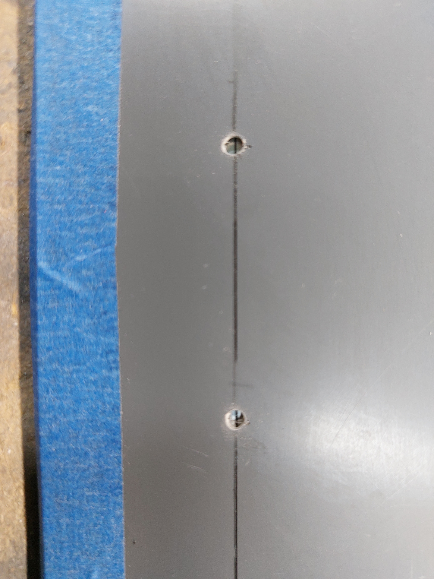
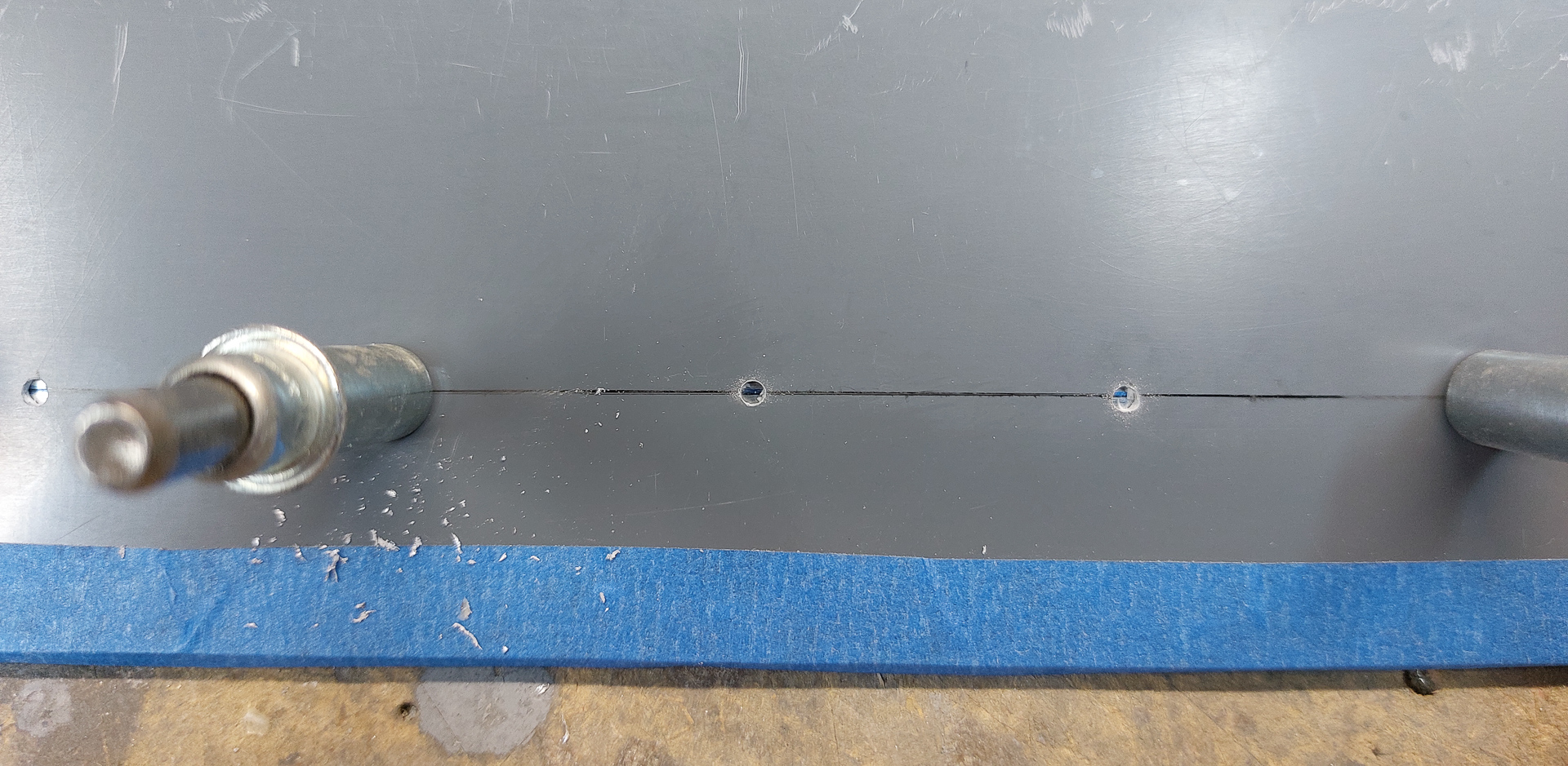
The line stays nicely in the center.
FInally I reamed all the holes to #40. I did have an elongated hole in the bottom so I mixed up some epoxy and filled it up again. As this had to dry, I moved on to the next fairing for measuring and ensuring no twist. Same procedure with the squares and then put the template on to mark the locations for the cuts.
This time, I measured the same amount extra cut back from the bottom side. This should work out perfectly. If it doesn't, my gear legs would have different lengths and I think I'm in a lot of troubles.


