

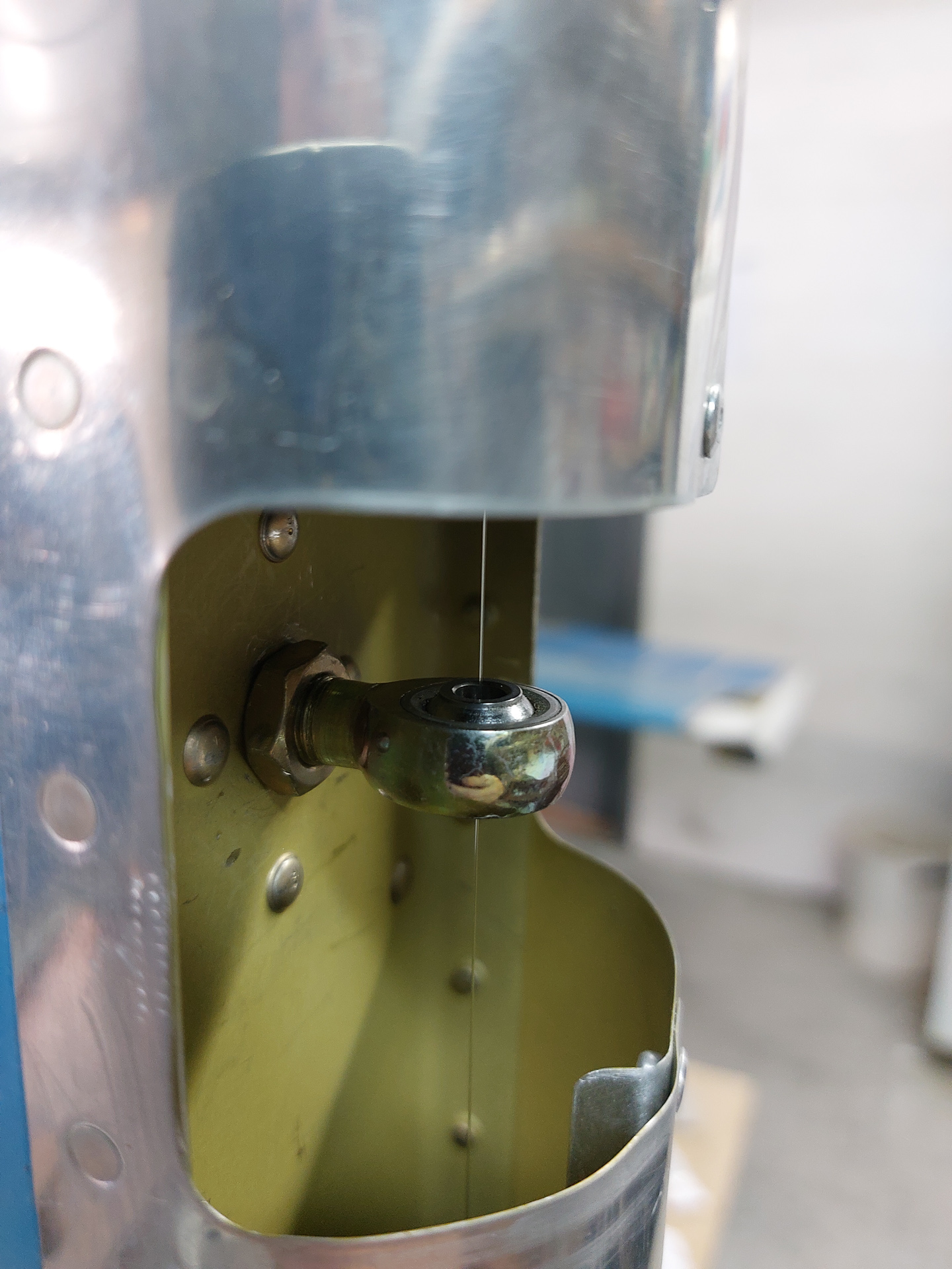
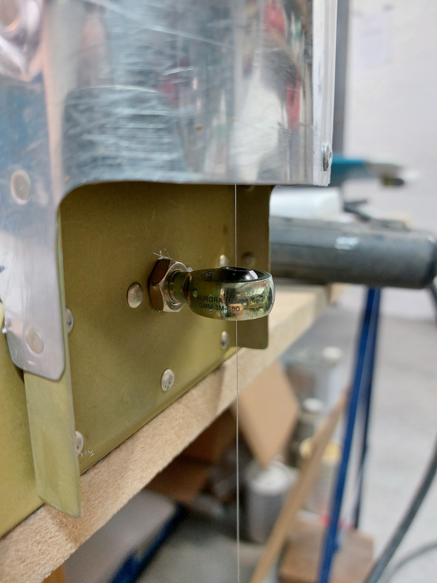
In last session I realigned the vertical stabilisor and remade the up elevator stop. With that task completed, I can continue working on the epoxy tips for the rudder and the vertical stabilisor. However, with the elevator position slightly changed, I needed to realign the rod end bearings that hold the rudder to the VS. The methode to do this is to run a fish line on a plumb bob through the holes of the rod end bearings and check that it runs straight through all three. Final tweaking is then done by try and fit on the VS itself.
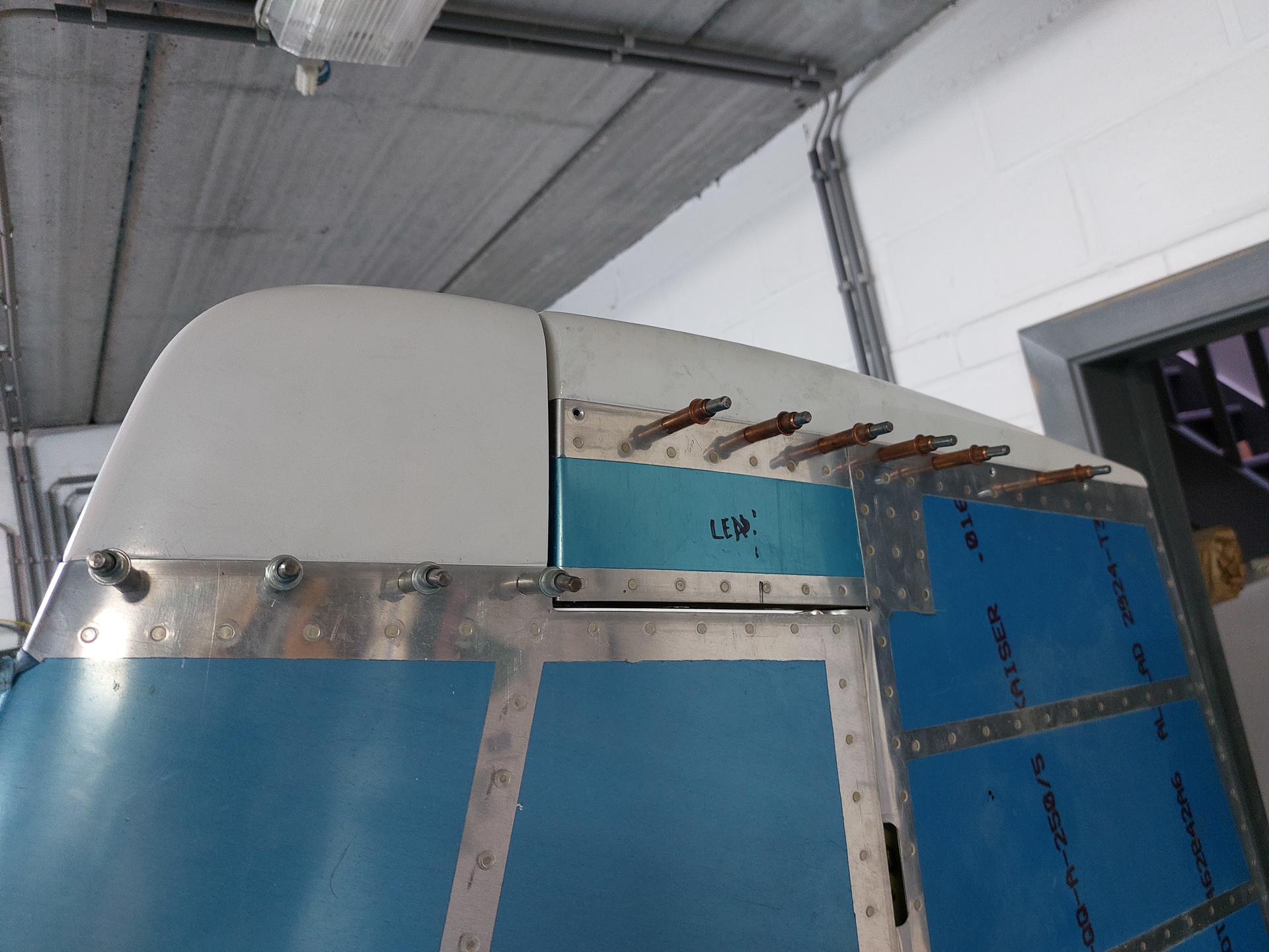
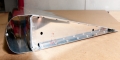
With the rudder installed and aligned in it's final position, we can now attach the top of the rudder fairing and the VS fairing in the front of it. The final position in the rudder is important as this defines the way you will cut the rear end of the VS tip fairing. I had already drilled the rudder top fairing in the past and the main task is now to define the perfect gap between rudder front and VS tip back. Just like with the HS tips, this fairing comes way too long and you will have to cut a fair bit of. I just installed it with the rudder swung to the side and positioned the VS tip, then brought the rudder back to touch the tip and draw the touching line. Do the same on the other side and you get a very good position to start the first cut. Then I cut off the excess and installed the tip back in place to see how much more I needed to cut/phile and sand to get the required gap. In the image below, I'm just passed the intial cut.
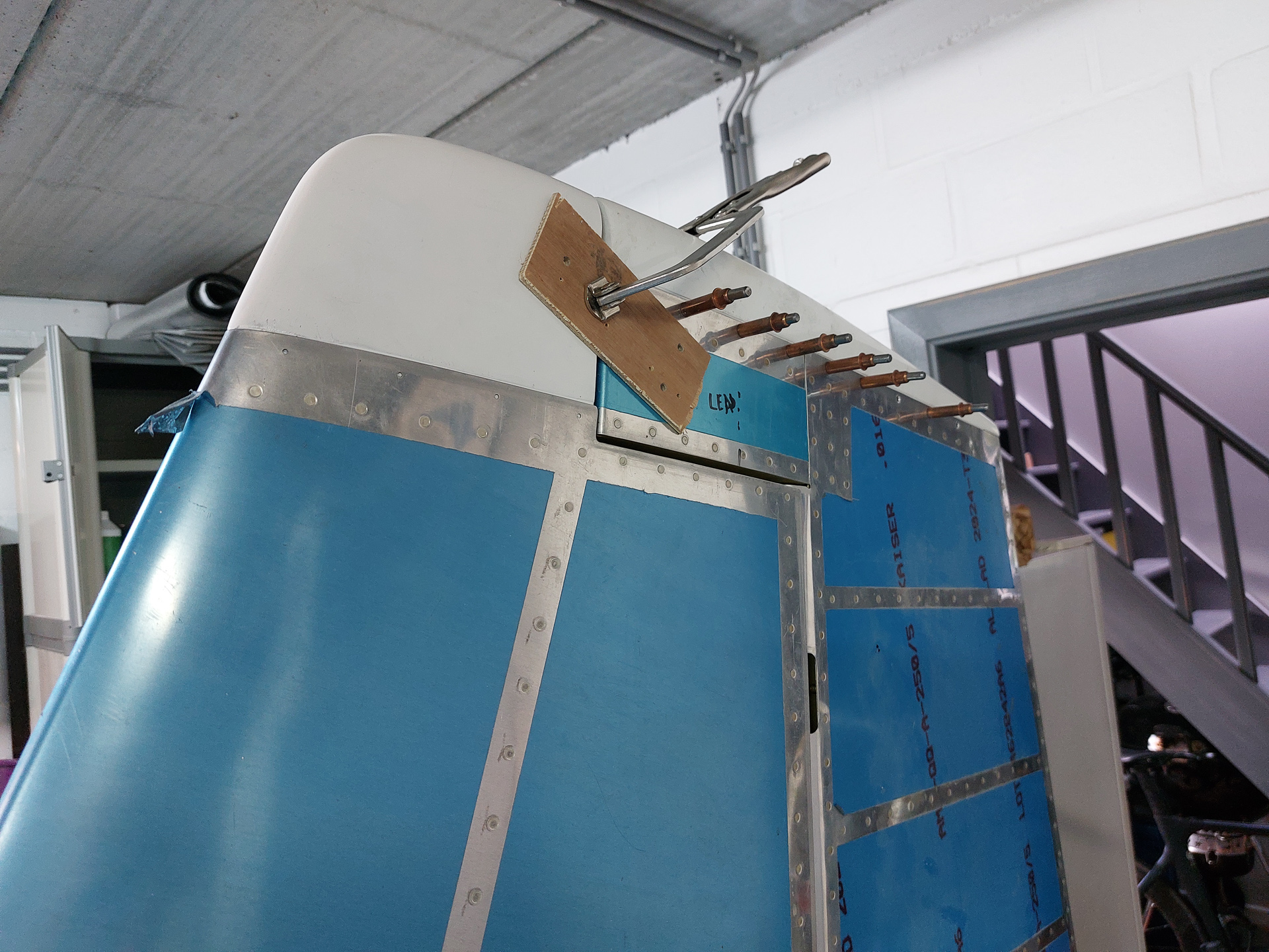
I brought the tip in alignment with the rudder arm and rudder fairing by using two pieces of wood and clamped that with a vise grip. This is important because the tip will tend to sag out and will be wider than the rudder fairing. This would create an ugly transition between the two. But clamping the tip in you define the final position and this give you the possibility to drill the holes along the bottom in the top skin of the VS. The image below shows the alignment seen from the front.
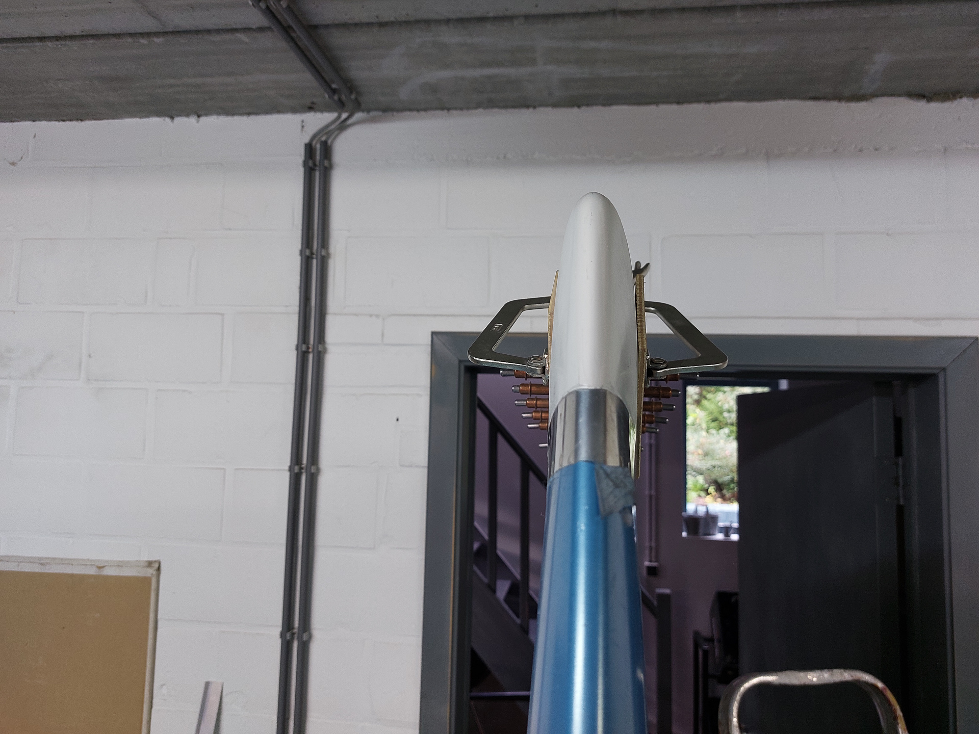
The holes are now pilot drilled #40 and the clamp removed. The sag has almost disappeared and the tip stays in position. There is still a minor sag but this will be neutralised once we glue the rear epoxy on the rear side. That will keep everything firm in position.
This is good enough for today, I will continue working on this in the next session.


