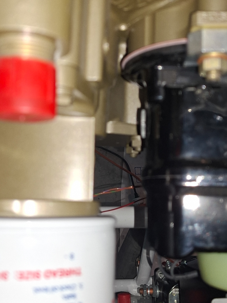
I had some small items to take care off on the electrical system.
First, I had to install the sensor reading cabling on the Dynon Amps shunt for the AMMeter.
The AMMeter shunt connects 2 wires from the EMS220 module pin 24 and 25 from the D37 connector to the Dynon shunt.
It uses these to sense the amperage flowing through the shunt.
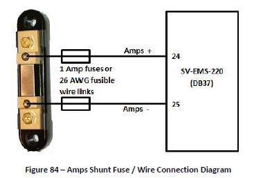
Depending on the position this has different meanings.In my case, the shunt is positioned between the alternator B-lead and the contactors on the positive side of the battery. This means according to the Dynon manual I'm in situation B. Position B–Ammeter indicates only the positive currents flowing from the alternator to both the battery and aircraft loads. (0A-60A). In other words it indicates the amperage flowing from the Alternator.
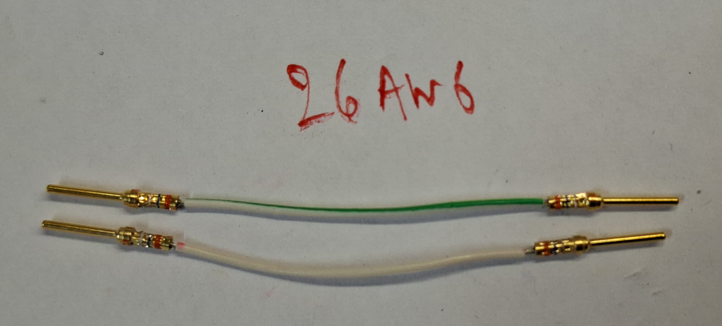
I was still missing the 2 fusible links in the drawing as I couldn't get my hand onto 26 AWG wire. With my last purchase from spruce I ordered a foot of multistrand conductor wire which had 26 AWG wire inside. After stripping the wire, I cut some pieces of 1.5 inch and put some DSub pins on.
On the shunt terminal side, I crimed a very short piece of 22 AWG on a 1/4" ring terminal with femal DSub pins onthe other side.
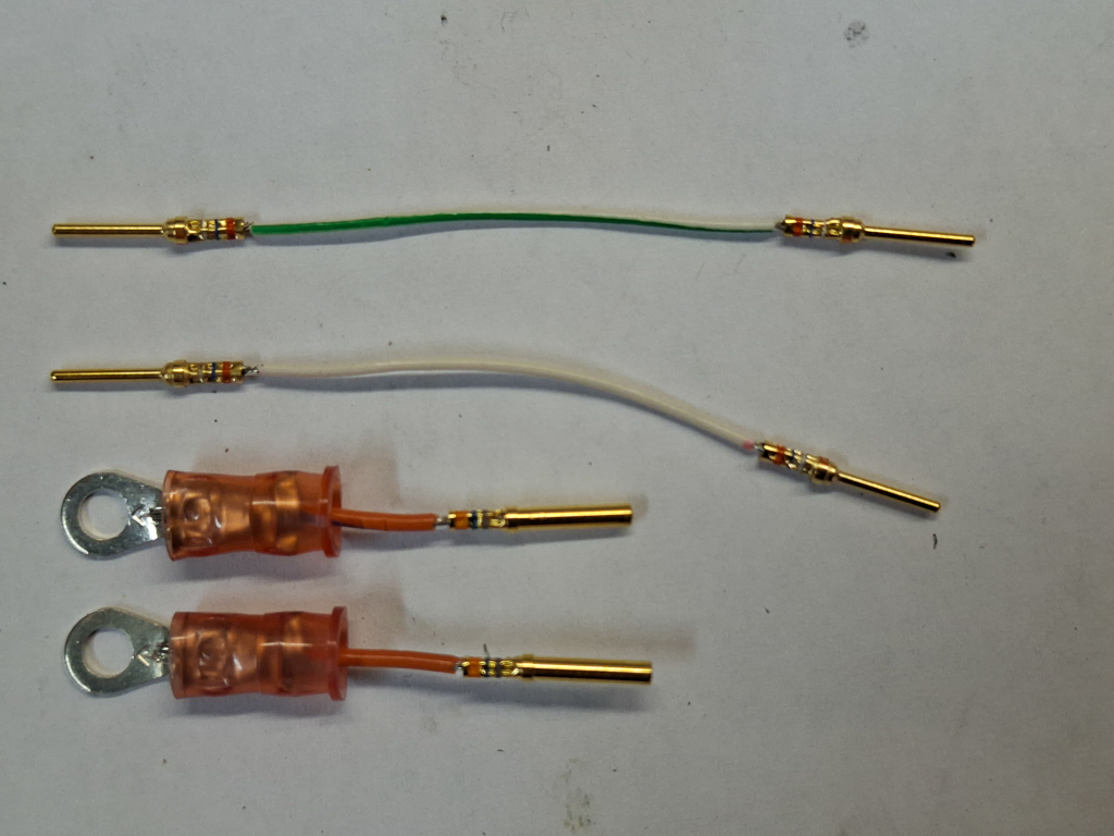
I will put heat shrink over these so that the connection is tight, creating a fusible link as mentioned in the manual.
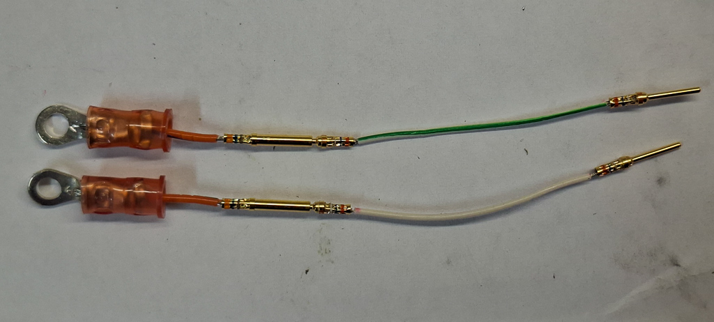
As the alternator belt is not yet installed and the engine not run yet, this was a theoretical excersise that can only be tested when the engine is running. Yes I could put a power source on the alternator side to test but I'm not going through that hassle. In the next image the wiring is connected with transparent heat shrink over.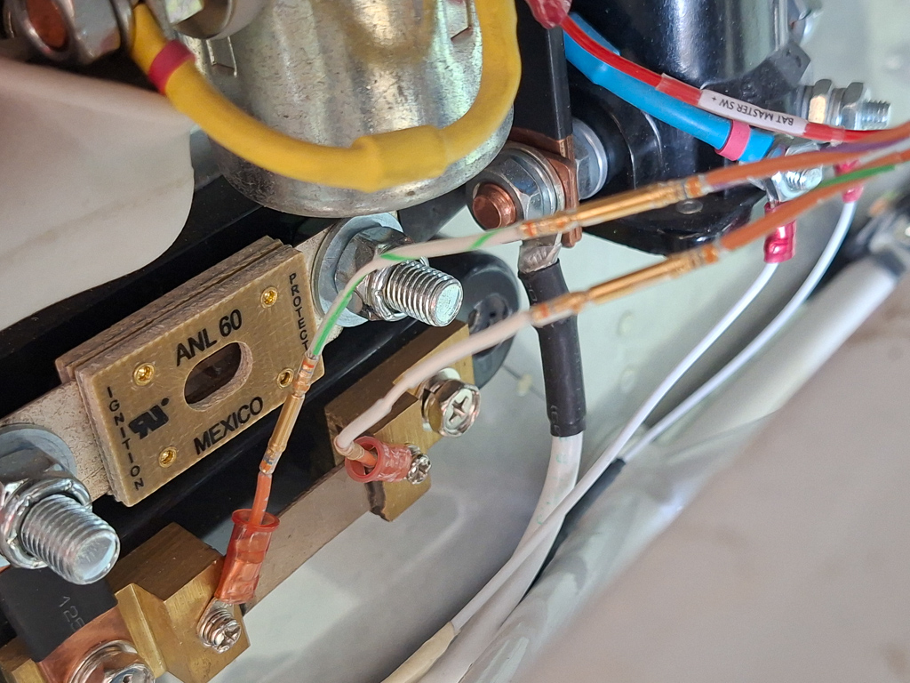
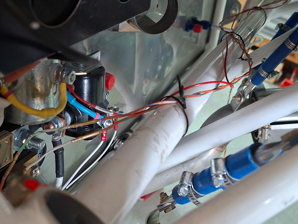
final bundling of wires and attaching them with adel clamps will be done once all wires have been installed but I do plan to run them of the lower engine mount bar.
Another small task done was the connection of the voltage meter pins to the SV-EMS-220.
Pins 1 and/or Pin 2 of the EMS D37 connector can be used to monitor the voltage in your electrical system (or any other DC voltage source) from 10-30V DC.
The manual says connect either of the pins to a point in your electrical system that you wish to monitor. However in the table of pin assignment for injected lycoming engines, the table says for pin 2
: "Yellow or Unwired -> No connection", and for pin 1 "Red -> Battery voltage (voltmeter input)".
So I ran the red Pin 1 22 AWG wire from the D37 pin 1 to the main entry power stud of the VPX. I assume the entry of the VPX is where I'll get the most accurate reading for the voltage indication.
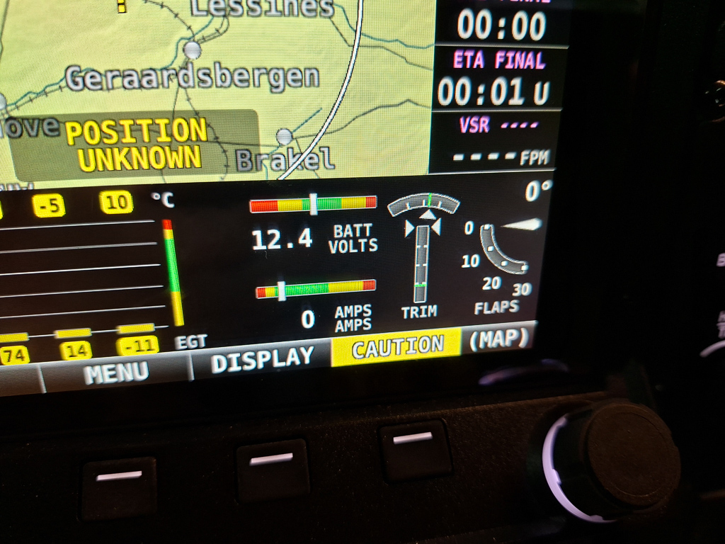
After I switched on the avionics, I saw 12.4V appearing on my display which seems to indicate the wiring is working. The normal voltage is over 13V but I assume at this point that this is when the alternator is running.
Next I ran the Tach sensor wiring from the firewall to the EMS sensor. I had to decide on a good point to splice the wire from the sensor to the wiring going to the pin 32 of the D37 Dynon EMS connector.
This pin is the Standard RPM Input Left (10+ volts).
I had ordered the "UMA TACHOMETER PICKUP FOR SLICK MAG 6 LEAD" T1A9_1 (Part# 10-02432) from Aircraft Spruce. This is a sensor that screws into a port of the magneto and does magnetic pickup for Slick or Bendix Magnetos.
I have ran a wire from the VPX J8-6 with "always-on" condition from vpx to the pos wire of the sensor and spliced them behind the sub panel.
Then ground wire of the sensor runs to the ground forest of tabs on the firewall. The signal wire is connected to pin 32 on the EMS. You only attach the L tach signal wire in case of a single engine airplane.
In the image below, the tach wires are spliced and visible as the pink splices in the center of the image.
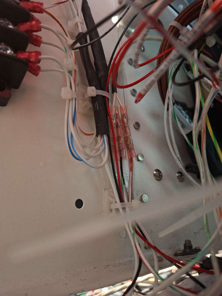
The sensor wire runs up the F-7103 sub panel under the F7107-L FWD fuselage rib and joins the rest of the sensor wiring along the F7101-L rib.
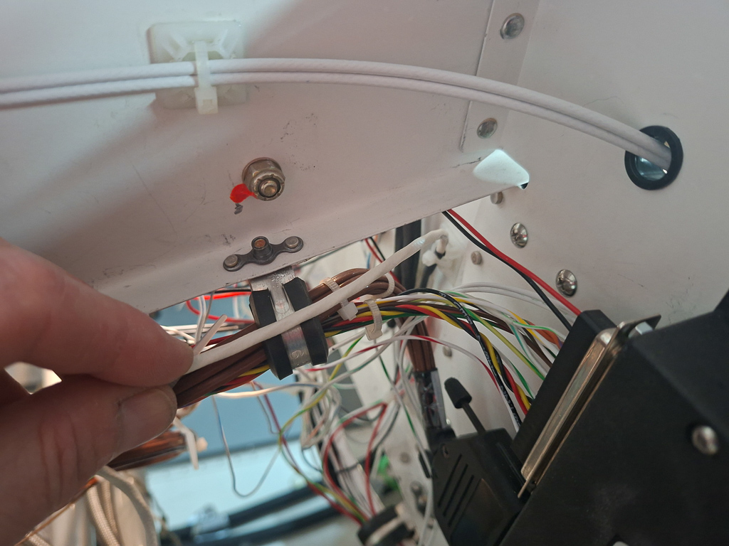
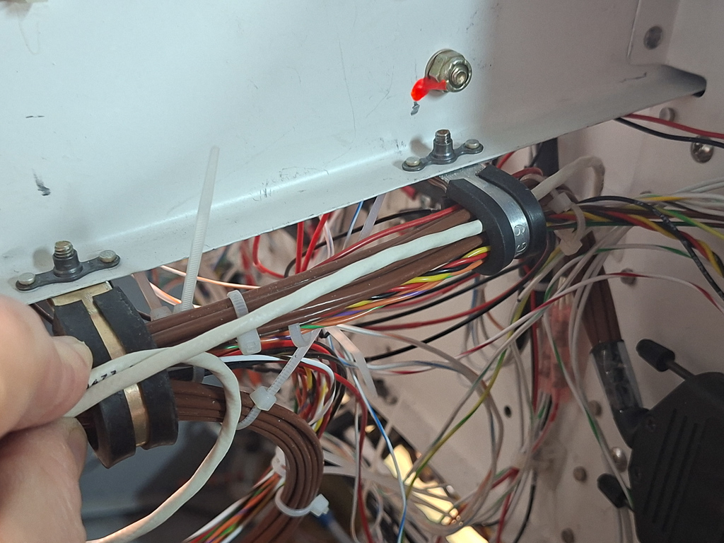
I kept a small service loop in the middle.
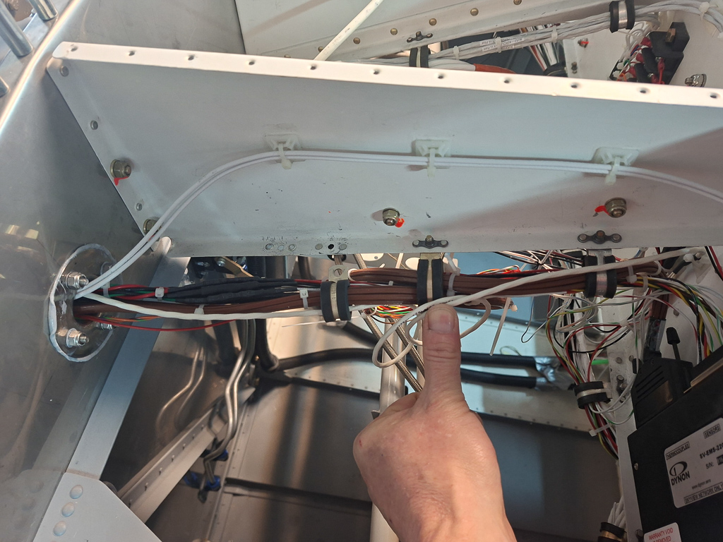
On the firewall forward side, the sensor will run along the engine mount towards the right magneto.
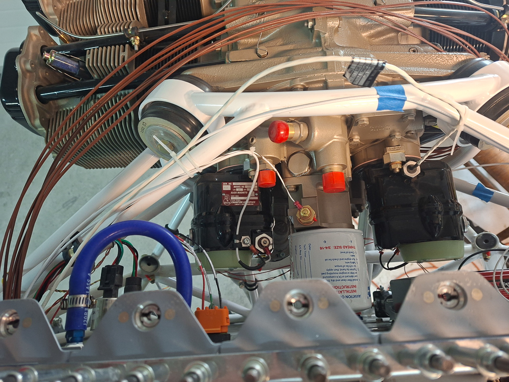
I couldn't connect the sensor yet as I couldn't disconnect the port from the magneto. It's very tight in there to put a wrench on. I'll probably do this when the engine comes off for the test run at PMM service center.