Short work session today. Decided to install the broken line disconnect resistor in between the AP disconnect button and GND.
The Dynon manual indicates this has to be a 5K ohm resistor which is placed between the switched side of the button and the GND line.
Dynon HDX software can detect in this way if the button is stuck and will check this on boot up of the system and give an on screen waning.
The manual states that it's an optional installation and that you may install a 4.7 - 5.3k ohm resistor across the AP Disengage/CWS.
More information can be found in Dynon install page 10-13.
I Installed the resistor between the black GND wire from the G407 pilot stick and the Disco AP button switch line on the G407 stick with butt splices under seat cover of the pilot.
When installed, you set this up in the Dynon setup screens : set SETUP MENU > AUTOPILOT SETUP > DISENGAGE BUTTON > ENABLE BROKEN LINE DETECT to “YES”.
The GND wire is cut in middle and spliced so that one wire runs to all other switches on G407, the split off GND wire is
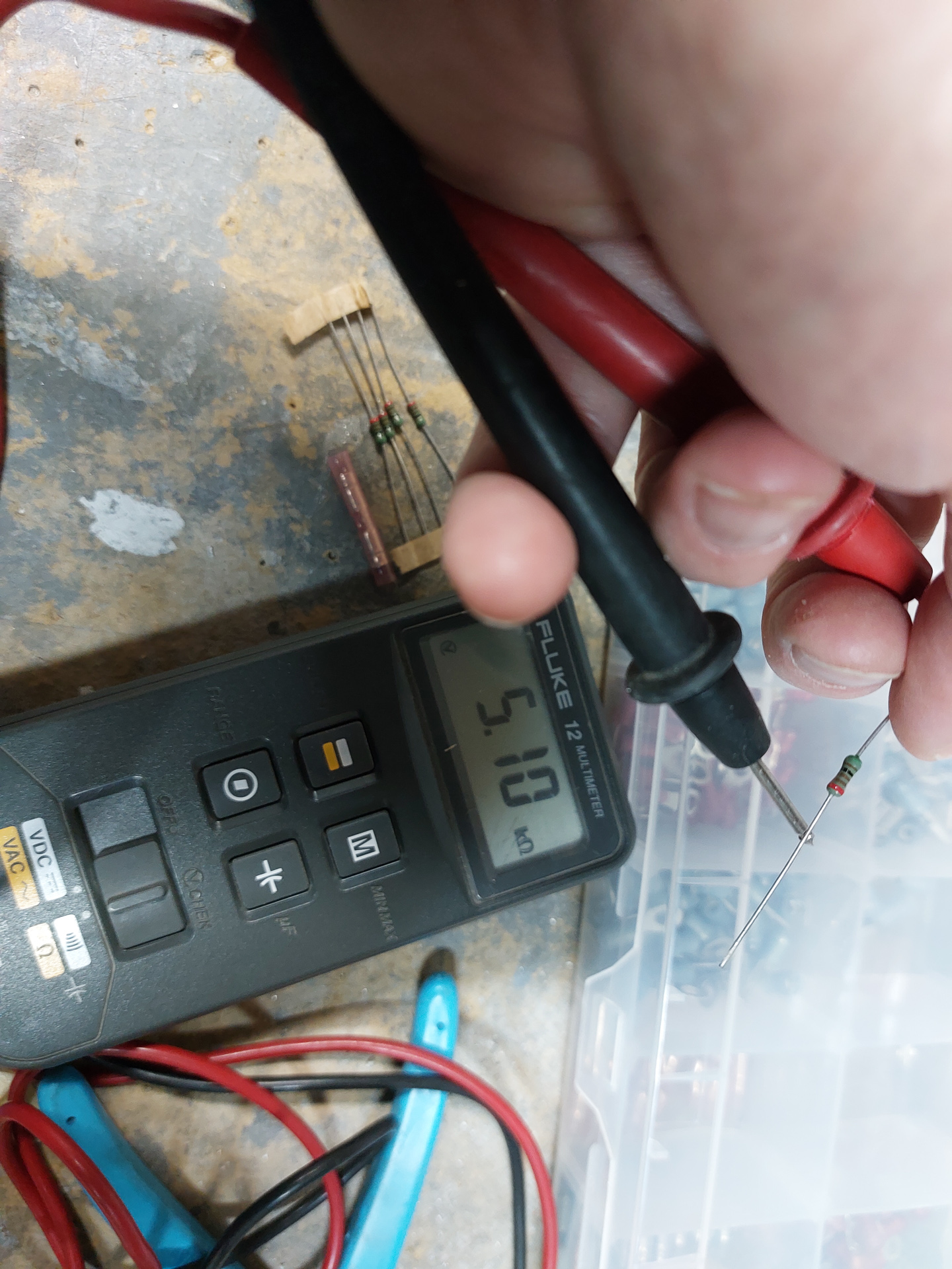
Verified first with a multimeter how many ohms resistor I had. 5.1Kohm...
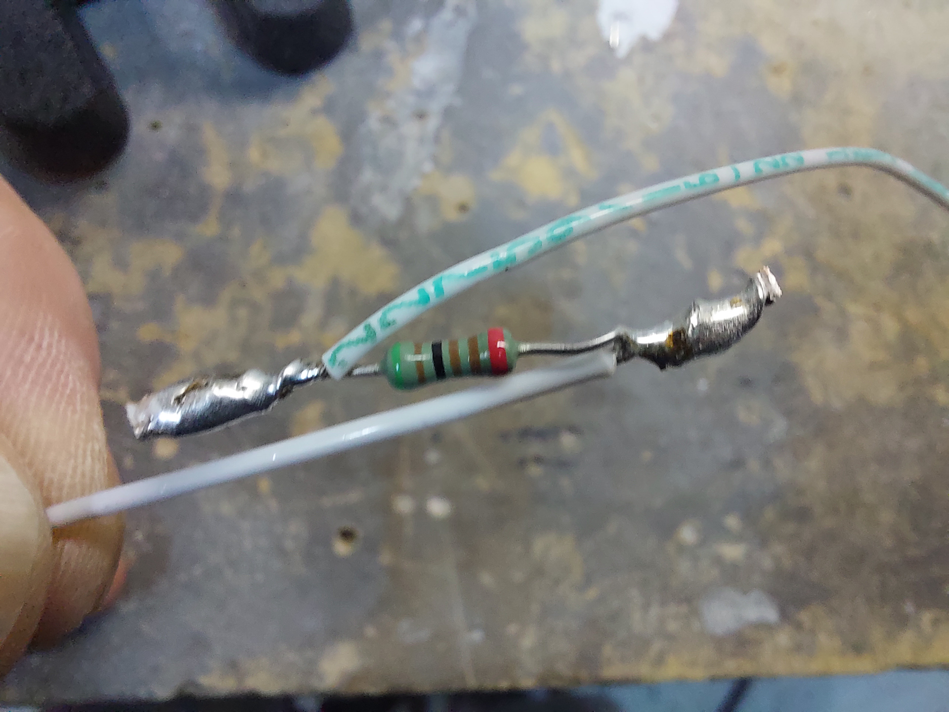
To solder a resistor inline with a wire, you need to solder it in a special way so that the stresses on the wire do not cause the connection to break. To to this, you need to solder it like shown in the image below. First the resistor is more or less mechancally twisted around the wire and then soldered. The wire is soldered to the opposite end of the resistor to minimize vibration stress.
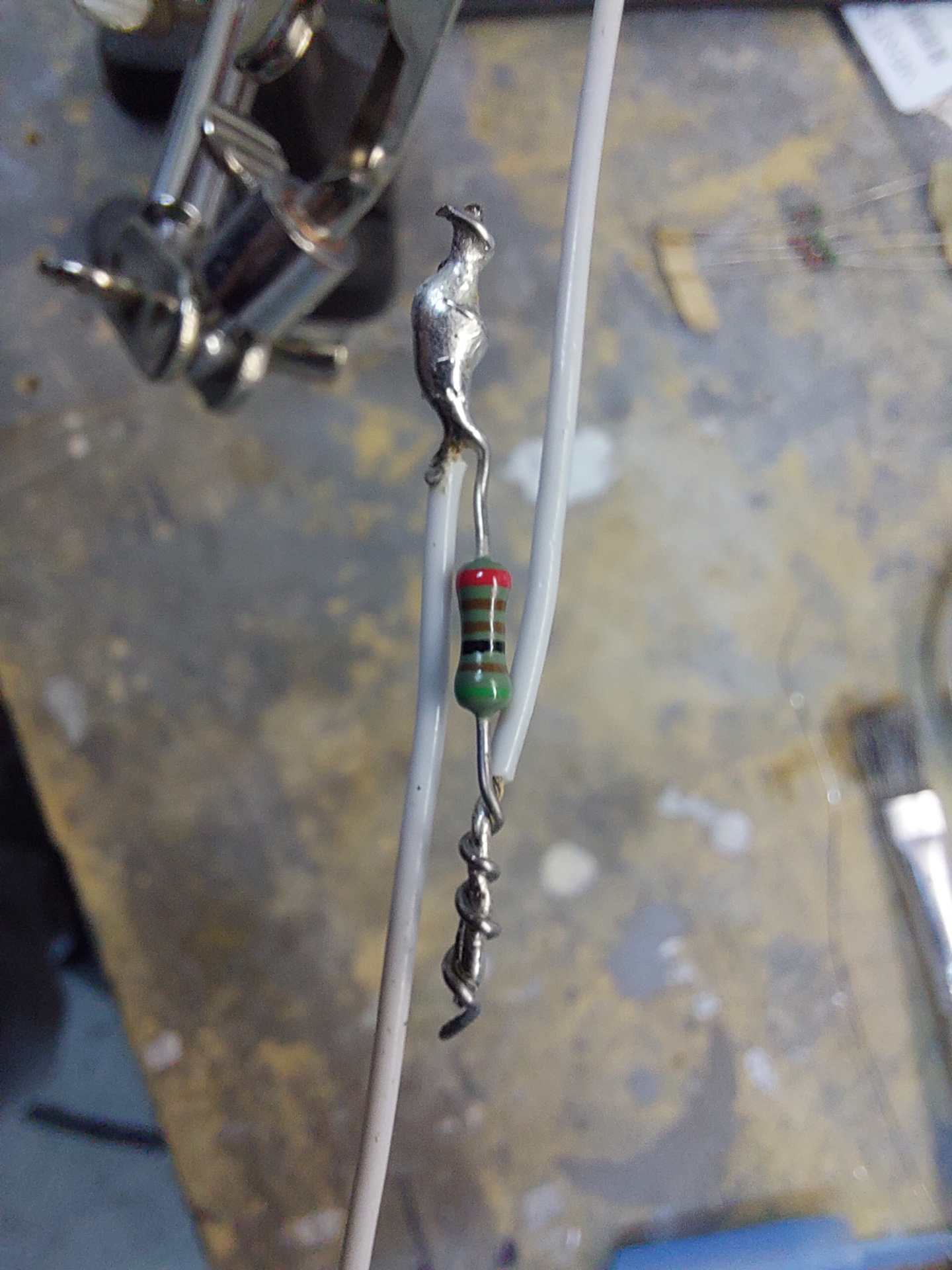
This is how it looks after soldering, just needs some heat shrink now to keep it all thight.