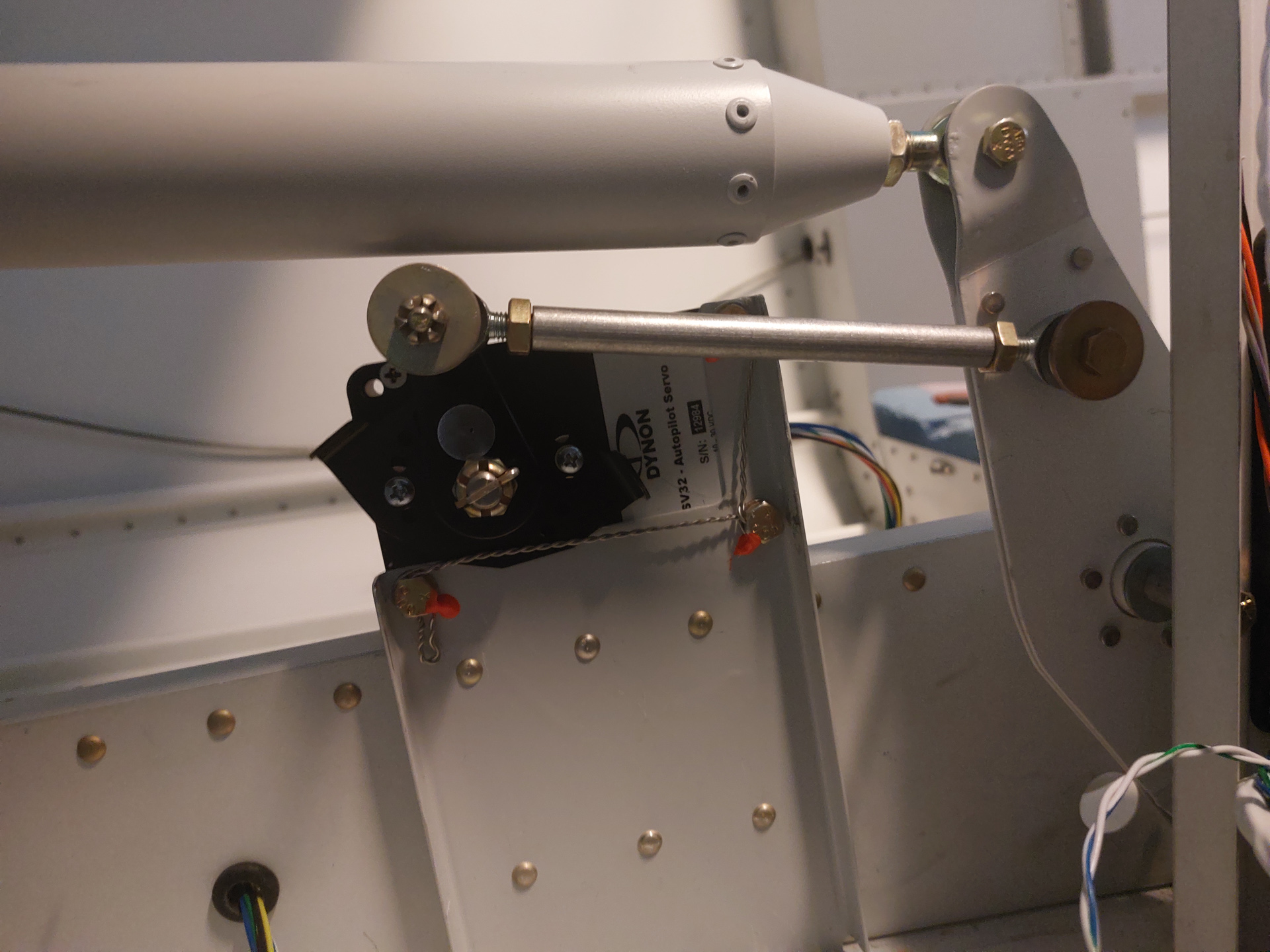
With the servo installed, I wanted to install the motion limiting bracket on the servo arm. The motion limiting bracket has multiple predrilled hole locations that allow installing it at different angles.
The whole idea hear is to ensure that the servo arm cannot pull the pushrod so far that it would lock up and block the movement of the pushrod. This would be a disastrous event if it would happen in flight as it would lock up the elevator control. The pushrod and the servo arm should be installed so that there is a 90° angle formed between the servo arm and the servo pushrod. This would allow full motion up and down (forward and back) on the elevator bellcrank. When installing the pushrod make sure this alignment is made and verify the arm in the extreme elevator locations full up and full down. Range of motion should never exceed 60 degrees from neutral throughout the control system's range of travel.
The additional protection to this is the motion limiting bracket supplied with the servo motor.
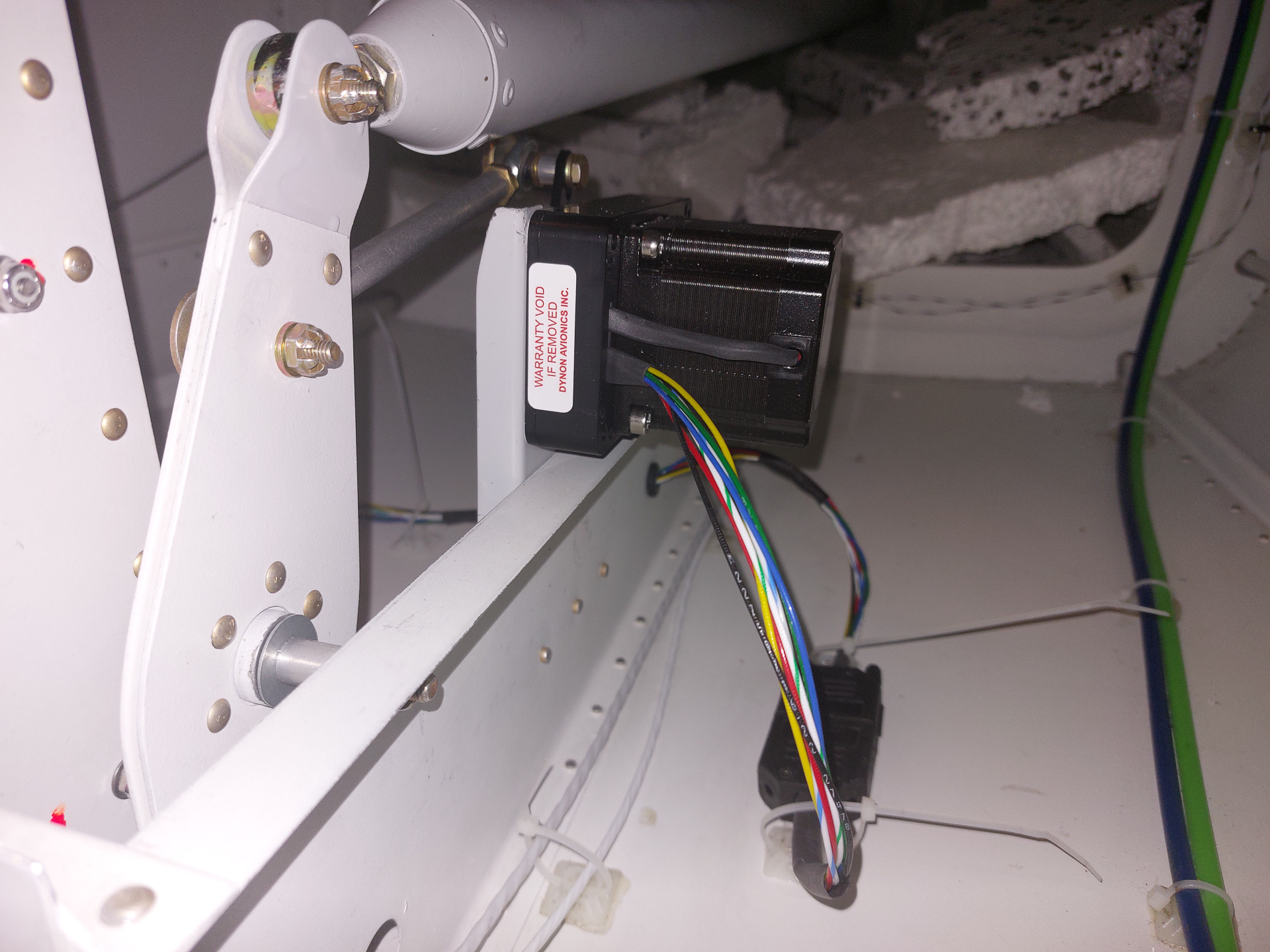
I updated the previous servo install article as I found out at this point that the motion backet will not be able to be installed with the servo already on the bracket. There simply isn't enough room to slide the bracket underneath the servo arm. I found this out the hard way and had to remove the safety wiring I had done before.
Installed the bracket and screwd the lock screws in place. Then reinstalled, torqued the motor and made a new safety wire connection. Lot's of extra rework for just a simple bracket. So on yours, don't forget to do this first.
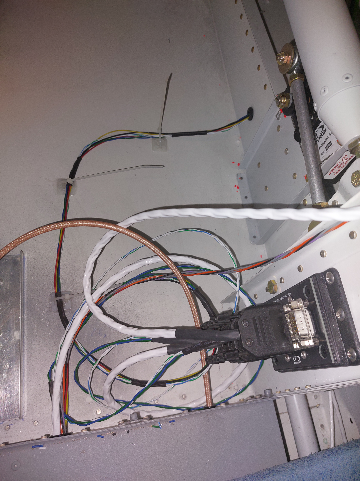
To finalize the work on the servo, I installed the wiring. Used Ziptie Mounting Bases to fasten the connectors with zipties. I glued them with different glue to the bottom skin as I don't trust the foam and glue that comes with these. I used a different glue after removing the foam from these mounting bases.
I run the servo wiring through F-729A bellcrank rib. A grommet protects the wires. On the other side the wire is secured with multiple zip tie mount bases.
The power and GND wire continue forward through the fuselage to VPX and GND block. The 4 skyview network data wires end here and are within a female DSub connector to the skyview network hub which is installed on the base of the F-728A bellcrank channel. I also ran the 4 data wires coming from the roll servo in the wing to this hub.