Next in the electrical installation is the installation of the Dynon roll servo. The gold colored anodized angle bracket supplied with the roll servo kit was already installed but I had to take all AN3 bolts out because the aileron bellcrank has to be drilled for installation of a nutplate that will hold the servo pushrod.
Also took some time to determine the correct length to cut the servo wiring so that it would not interfere with the aileron bellcrank and still have sufficient length on the wing root side.
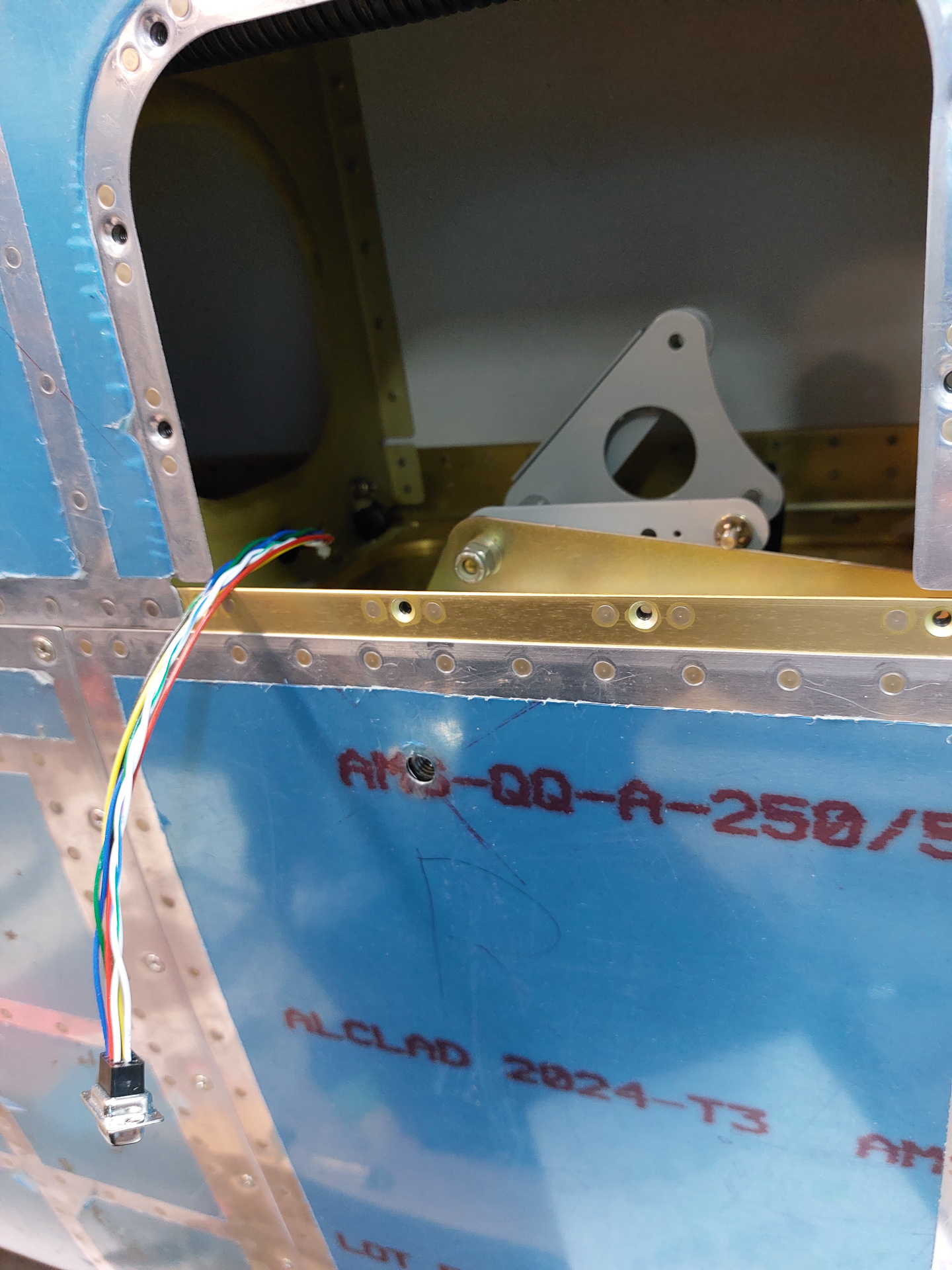
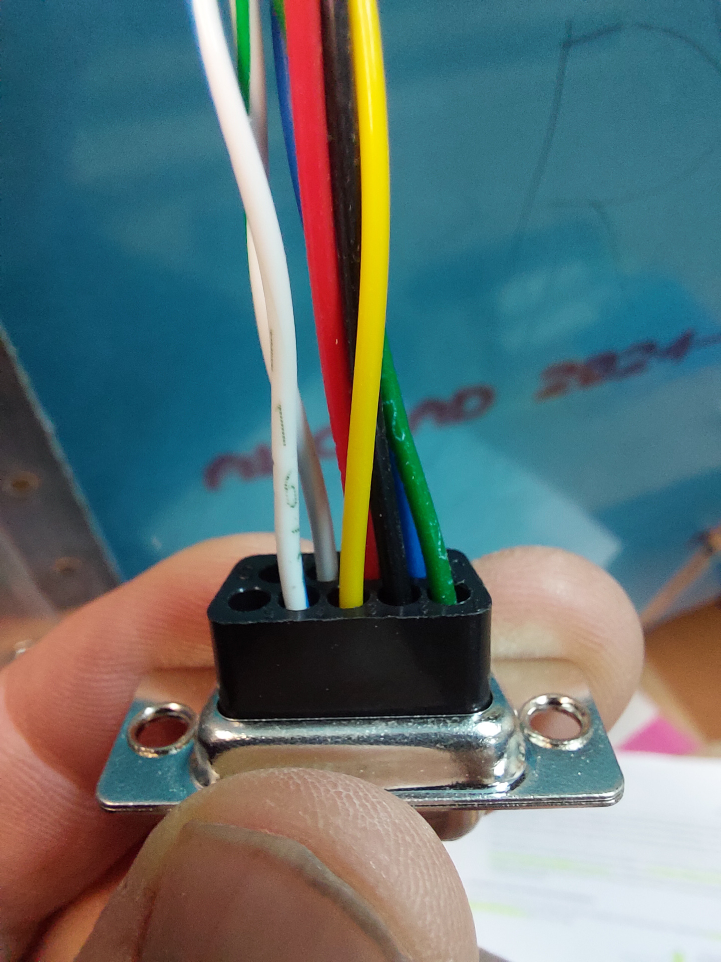
Crimped the DSub pins and installed in the connector. This contains 2 pair of data cables and a servo power and GND line. The Servo power and GND line connect directly to the electrical system and are NOT connected to the servo network. The servo's draw too much power to install on the regular Dynon network data bus. The manual states explicitly that you may damage the system without warranty if you connect the servo's power to the network hubs. My servo power runs straight from 2 VPX power pins and black GND goes straight to the GND bus on the firewall. I isntalled an extra switch on the panel that disconnects power to the roll and pitch servo's with a simple switch to OFF. Using the VPX logic to switch of power pins is similar to mechanically installing a switch between the lines. With the VPX way of doing things, there is no load on the switch.
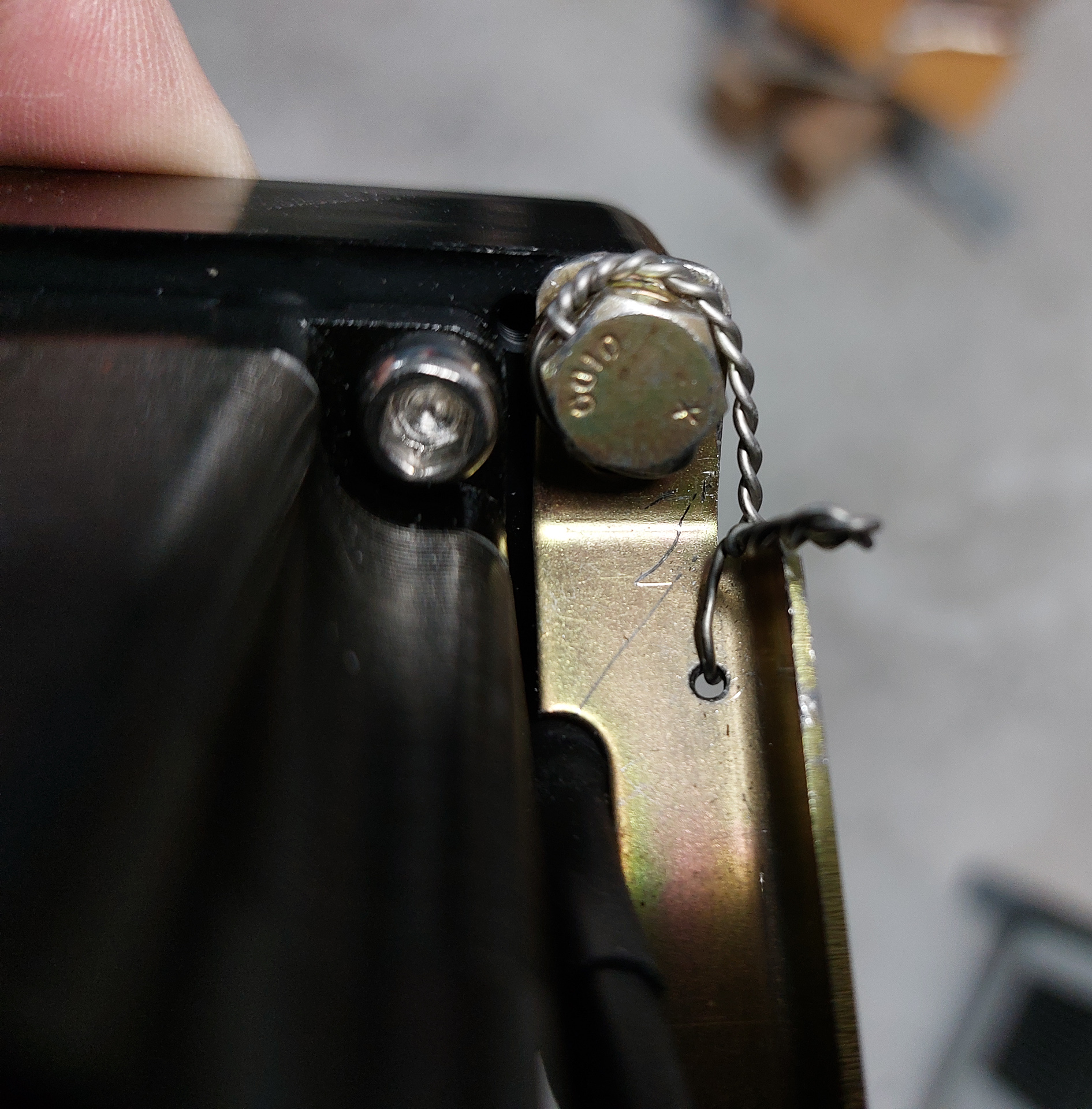
The space through the inspection hole in the wing skin makes it difficult to install the motor. I took the support bracket out and installed the rear bolt on the workbench. I drilled a small hole in the bracket and used it to secure the safety wire of the bolt. View from the side:
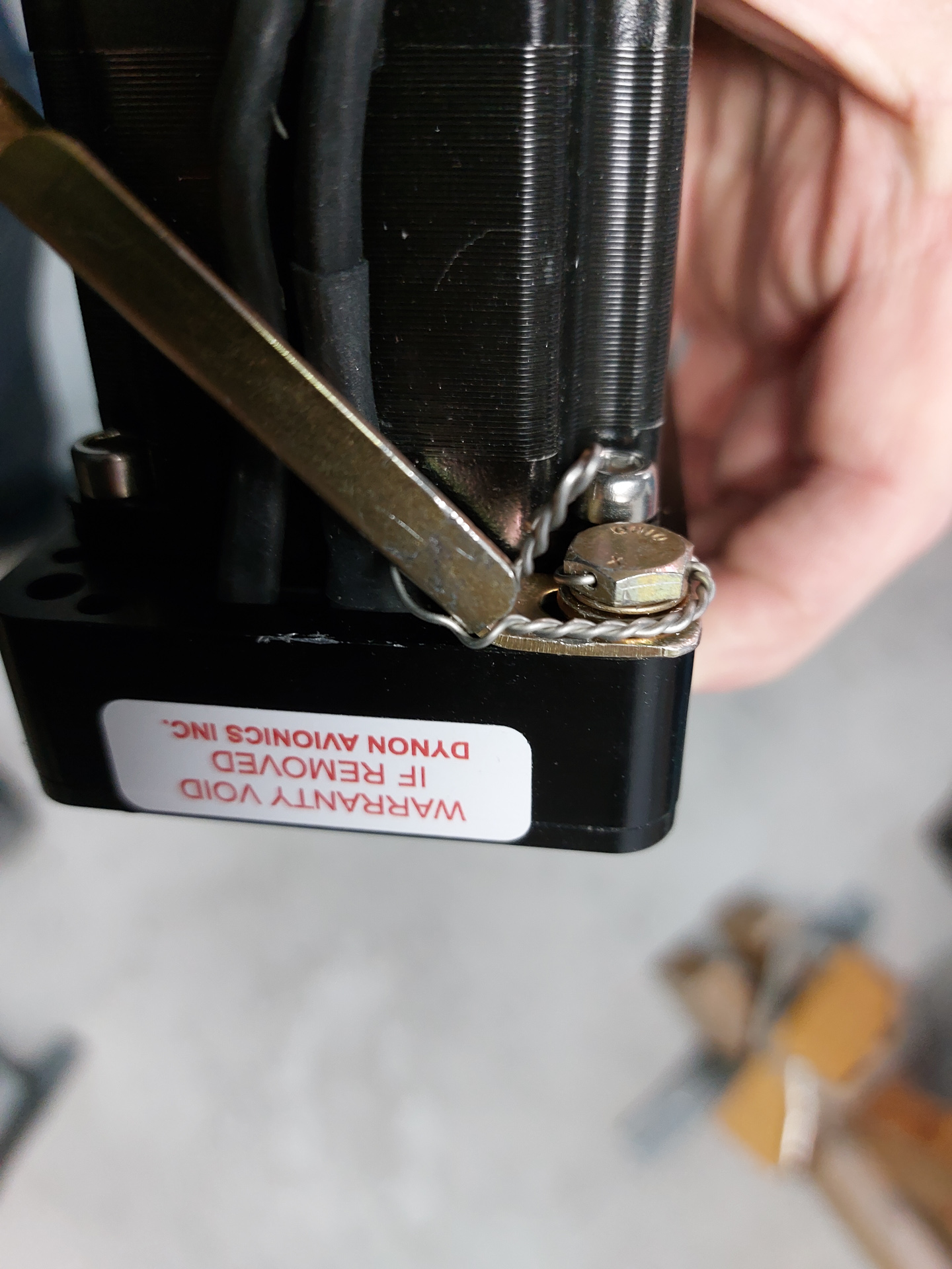
Safety wire view from the back.
Then placed the servo in it's location on the servo attach bracket. Routed the wiring and installed some adelclamps in the critical places where you need to keep the wiring away and secured from the aileron hinge bracket movement. I drilled 2 holes in the rib for AN515-8R8 screws and reused one of the aileron attach nutplates. Installed next size (length) bolt on this because of the extra gauge of the adel clamp ears. Secured the connectors on the main spar with some strips.
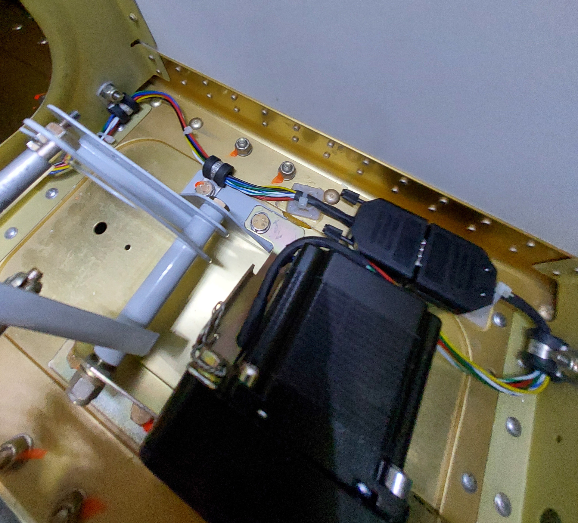
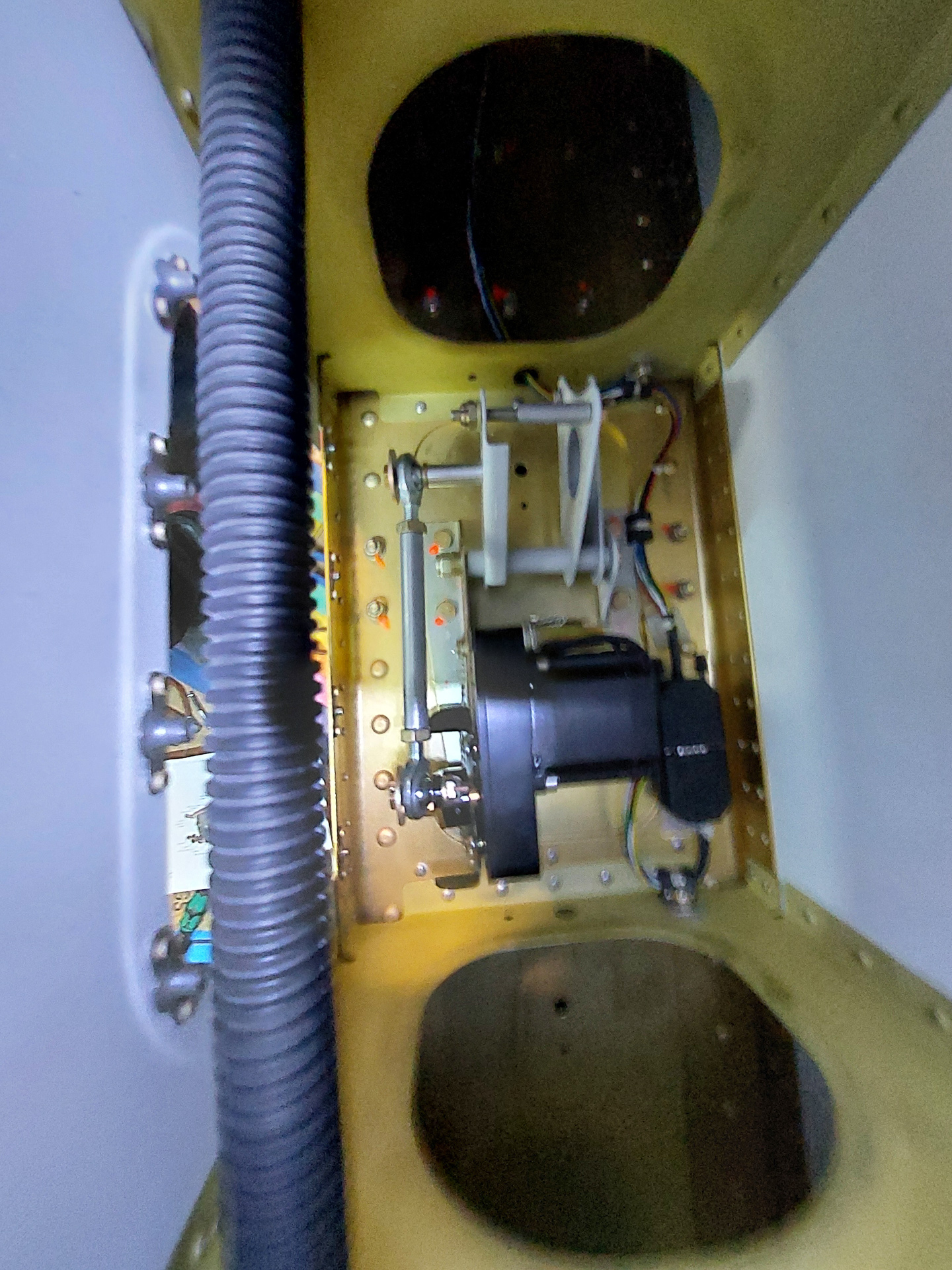
Same thing view from the rear spar.
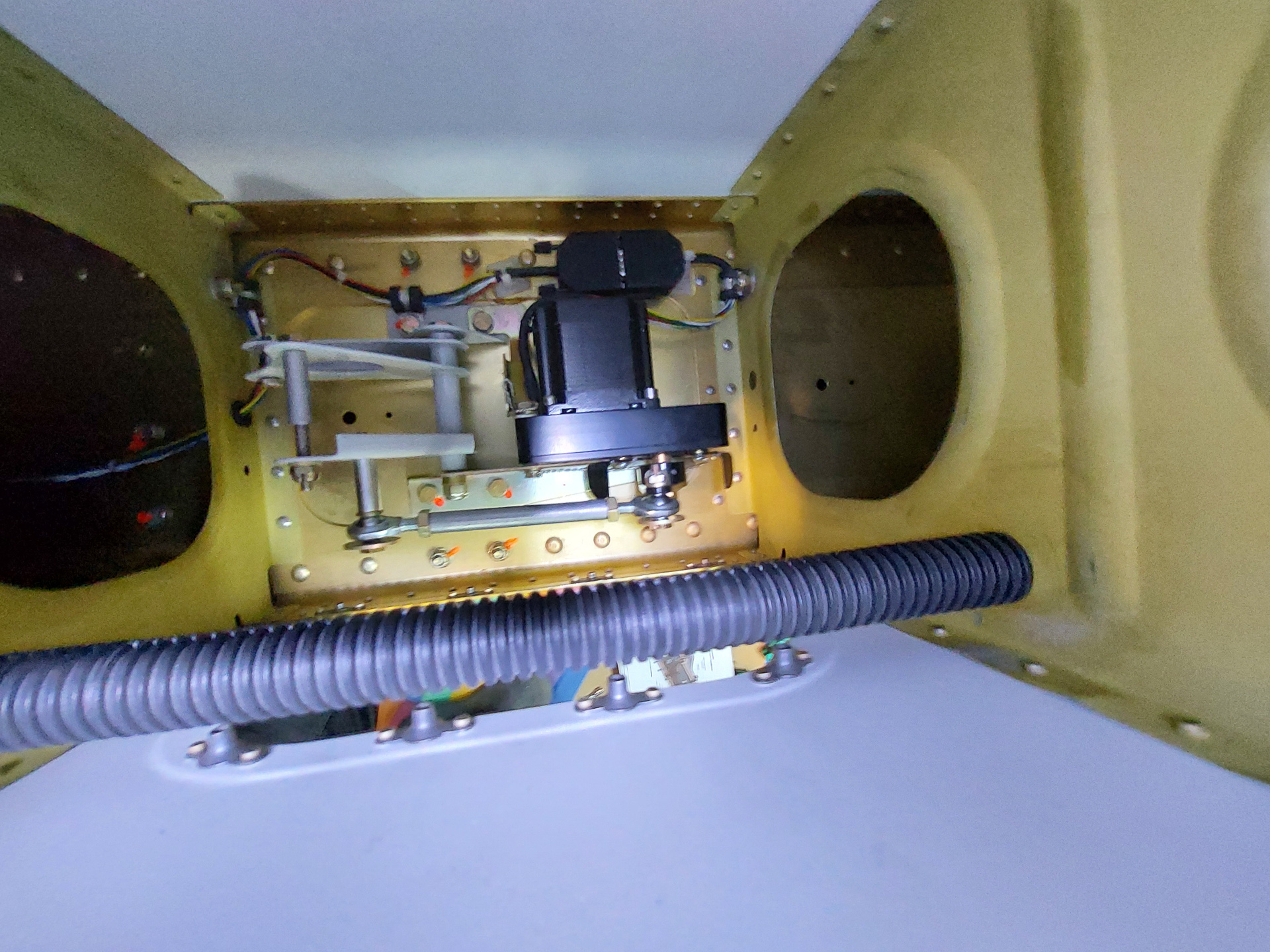
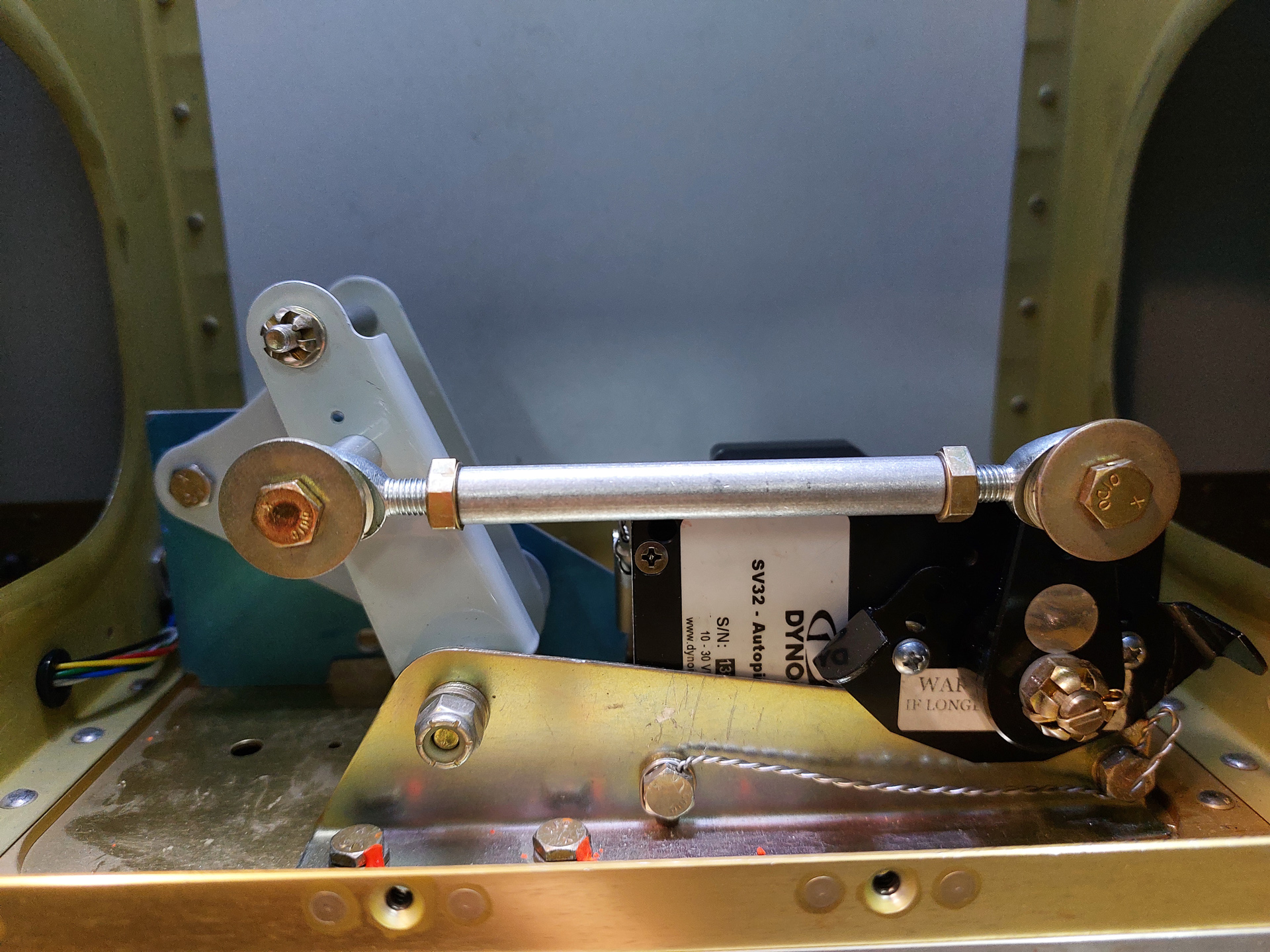
Front view of the servo with the pushrod temporarily installed and the bolts safety wired. On the aileron servo, the servo arm is nicely in it's 90° top center position with the aileron bellcrank in it's neutral position. (use the jig supplied with the wing kit to place the aileron bellcrank in it's neutral position).