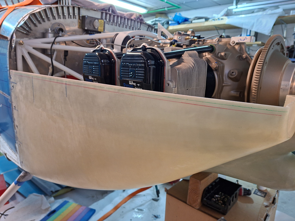
Earlier I had finalized the horizontal side line of the bottom cowl and committed to this height.
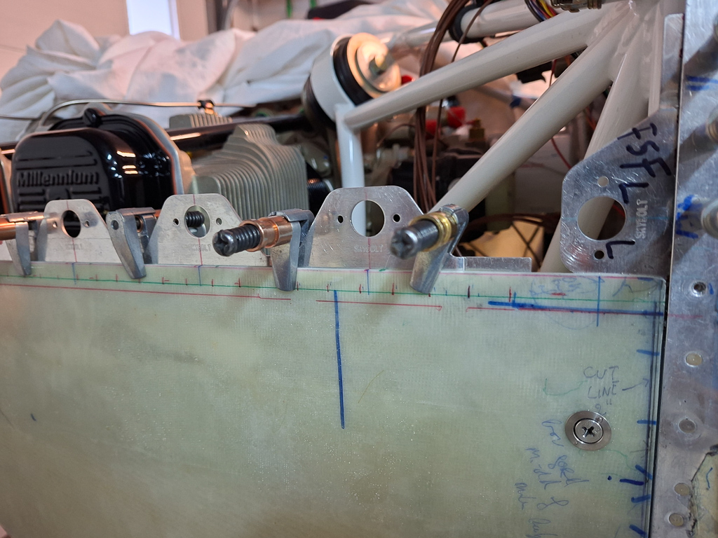
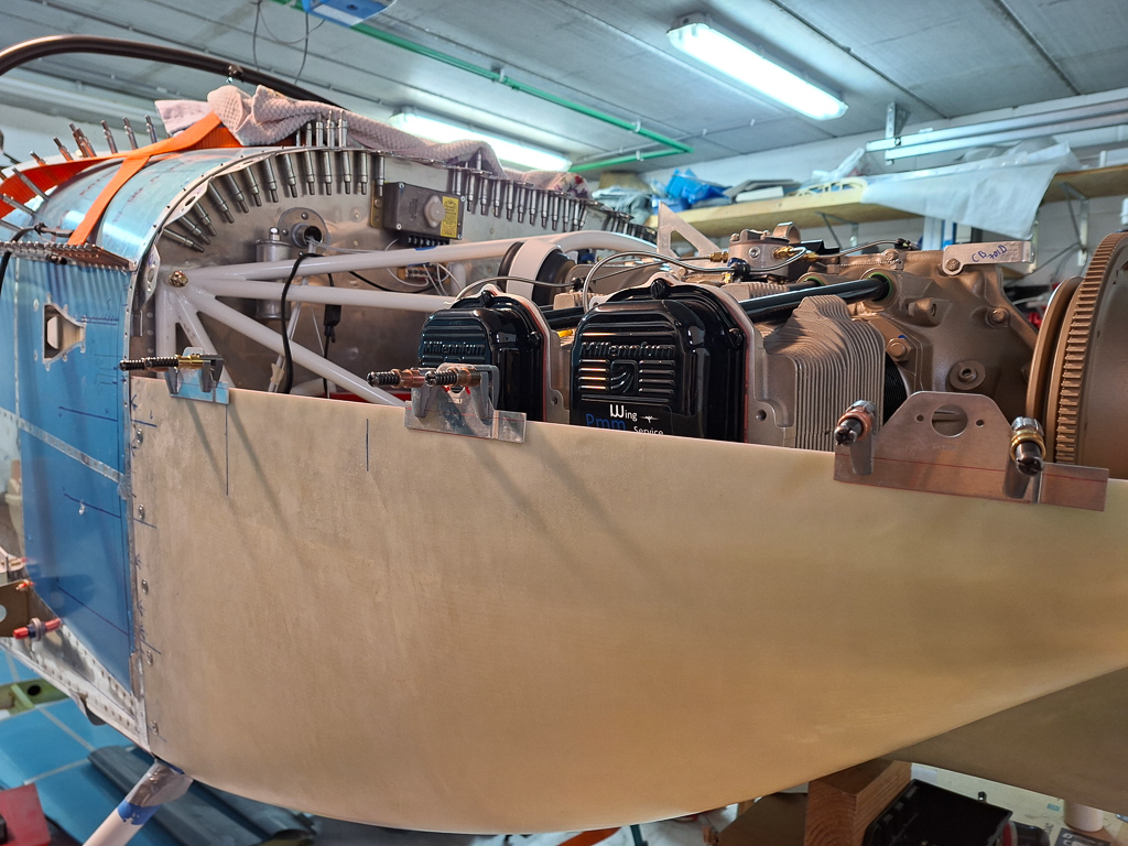
Today I drilled the pilot side flanges on the horizontal split line of the bottom cowling. I played a bit with the spacing and found that 3.4" gave me a good spacing measuring from the firewall FSF-L flange forward to the front of the cowling. I wanted to make sure that the spacing was equal along the line and that the last receptacle would be pretty close to the front near the air inlet. The prescribed 3.5" in the manual places the last one too close. Shortening to 3.4" means you have to shorten the tabs a bit on the non curved side.
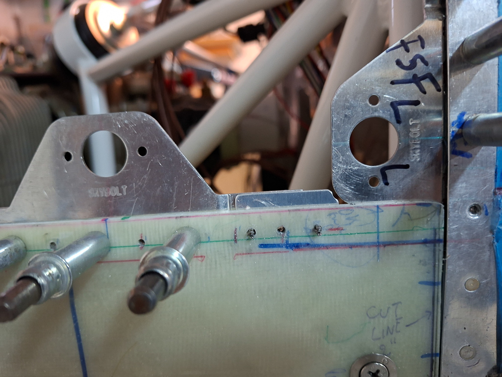
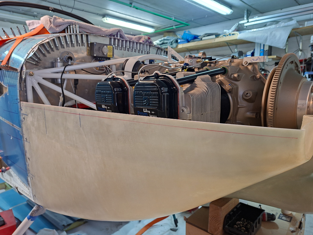
The cleco-clamps are really useful again in this when repositioning. I drew the locations on the top line with a ruler and marked the epoxy every 3.4", then positioned the middle line through the center of the flange on this mark. The red line in the image is the bottom of the flange if it extends 0.2 passed the edge, the green sharpie line is where I will drill the holes through the plexi in order to have sufficient edge distance on the flanges for AD3 rivets. I don't have a rivet fan and this is one of those places where it would have been really handy. Had to measure all rivet positions with a ruler and pulled som black marks over my green drill line. These rivets will be countersunk deeper so that a layer of epoxy will cover them, so you will never see them but force wise, it 's better to have equal spacing between the rivets anyway.
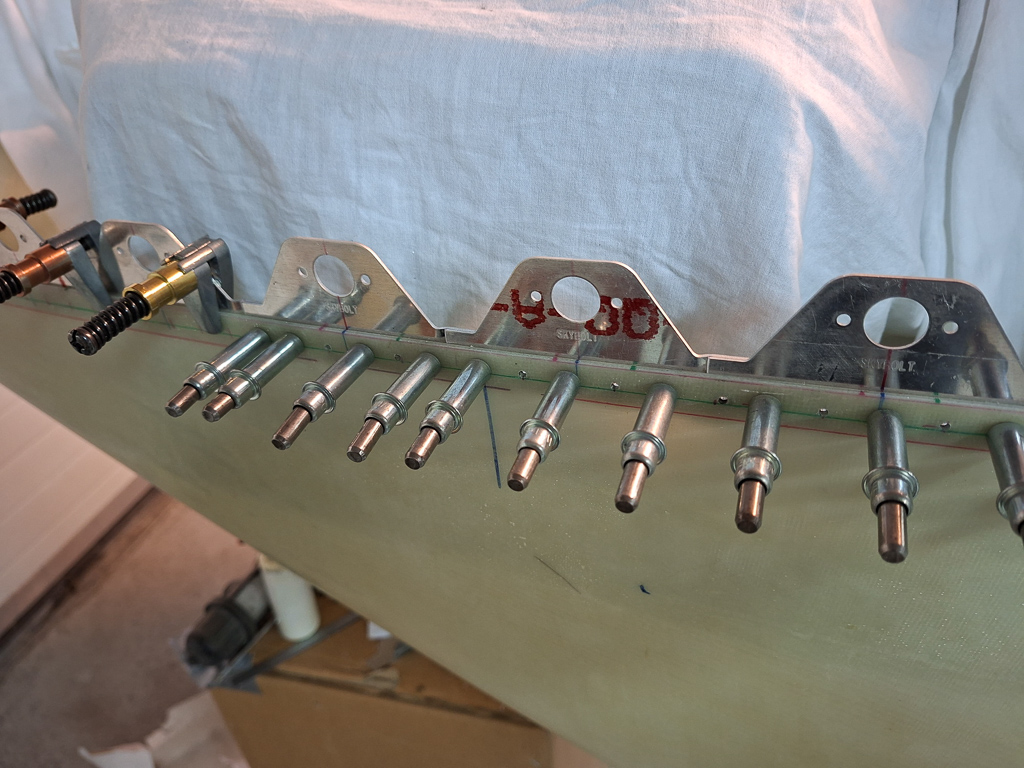
Drilled the first ones and put clecos in place. I will probably not need any shims here as the top and bottom cowl have equal thickness.
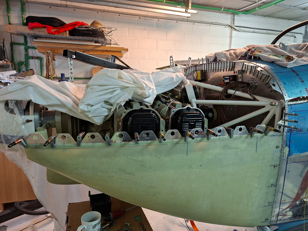
All flanges drilled. The last couple of flanges need some light bending to fit to the curvature of the front of the cowl. Later on I will also need to bend them inwards a bit to allow the top cowl to lay nicely against the flange.
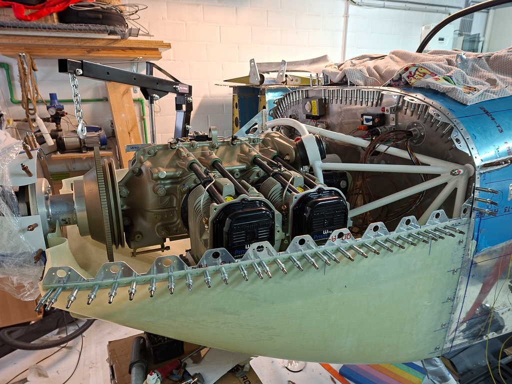
The offset of 0.2" allows hiding small gaps between upper and lower cowl. At the last flange before the FSF-L flange at the firewall, the last flange does not cover the entire length up to FSF-L so I made an additional small shim to place underneath the last flange closing that gap.
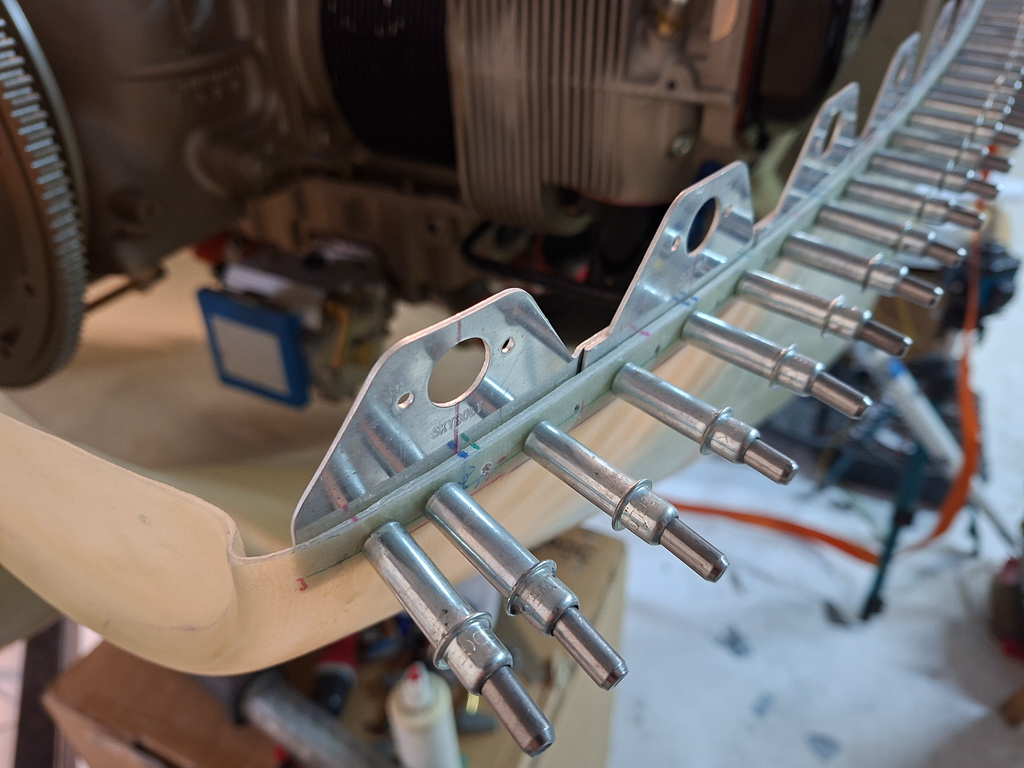
This image illustrates the curvature of the front of the bottom cowl. The flanges also bend outwards a bit so up to halfway, they will gradually have to be bent inwards. Lightly in the middle of the cowl , increasing towards the front.
I had some time left and started doing the same operation on the passenger side, drawing the lines.
Using the flexible ruller
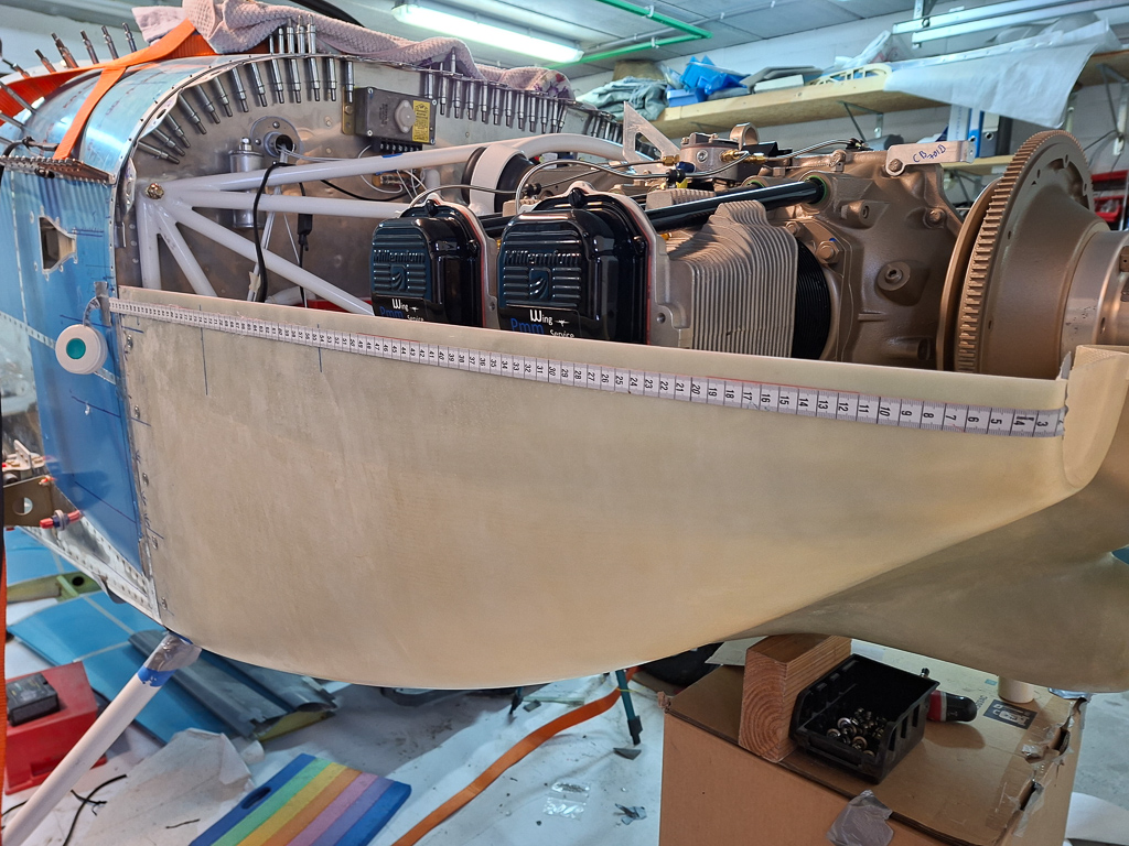
transferring the line
And measuring back for the minimum edge distance on the flanges