The skybolt flanges on the top of the firewall are final positioned. The offset of 0.2 from the edge equal for all flanges. I drew some lines on the middle of the flange extending on the fuselage skin so that I can remove and place them back in the same position.
Many of the flanges need slight bending and near the engine mount significant bending. I did this by hand using a vise and a wood block. You can make a nice curve this way in lack of large and expensive equipment.
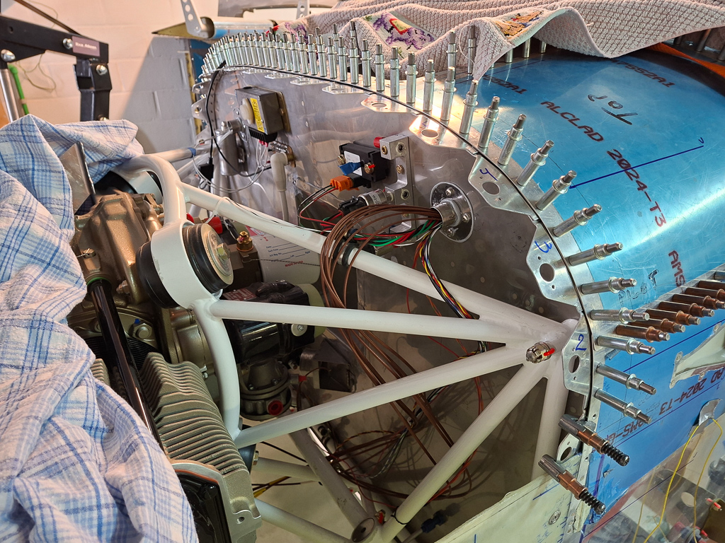
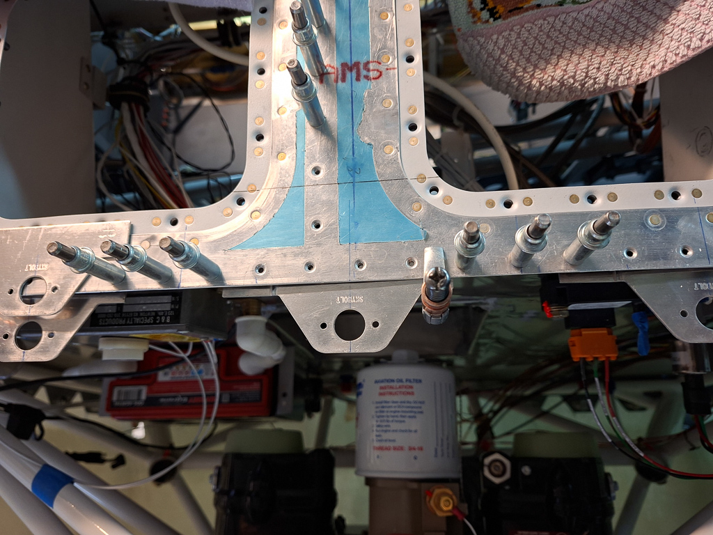
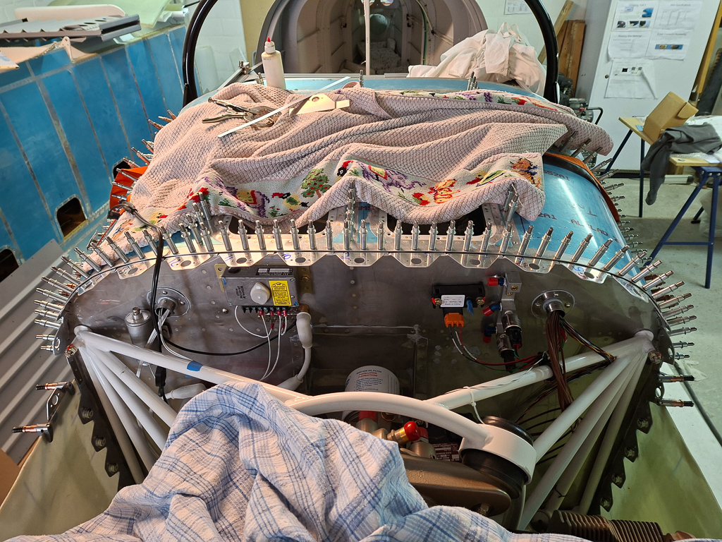
One of the challenges is that you need to drill through the flange but the top fuselage skin is not yet rivetted on the firewall plate. They tend to be moving out of alignment. If you would only clamp the flanges with no clecoes to keep the skin together, you risk enlarging the hole of the top fuselage skin (the drill will go through the top fuselage skin and find the harder steel plate underneath and pulls the drill to the side causing an enlarged hole in your fuselage skin). To prevent this, I removed the flanges left and right of the one I'm about to drill and installed clecoes in the skin so that the holes are better aligned prior to drilling. This is shown in the image below. The flange shown here is the top center flange. Notice also that my top flange is installed on the centerline of the fuselage.
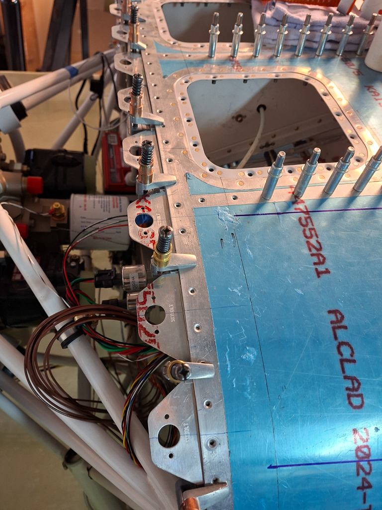
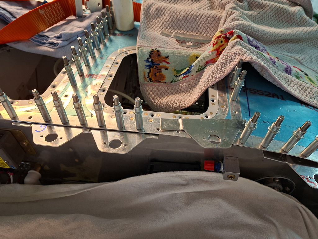
Same idea viewing from the top
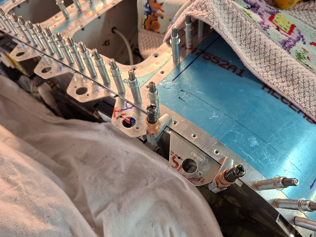
As the first ones are drilled, moving down to the sides, each time removing one extra flange towards the bottom and repositioning the one removed previously. It requires a lot of remeasuring but the technique works well.
As mentioned above, some flanges need some bending on them to follow the curvature of the top fuselage skin. Placing it in a vise, clamping and applying gentle pressure using a wood block makes this easy. Move it up 1/4" inch in the vise and push some more. Doing this over the entire length will create an even curve.
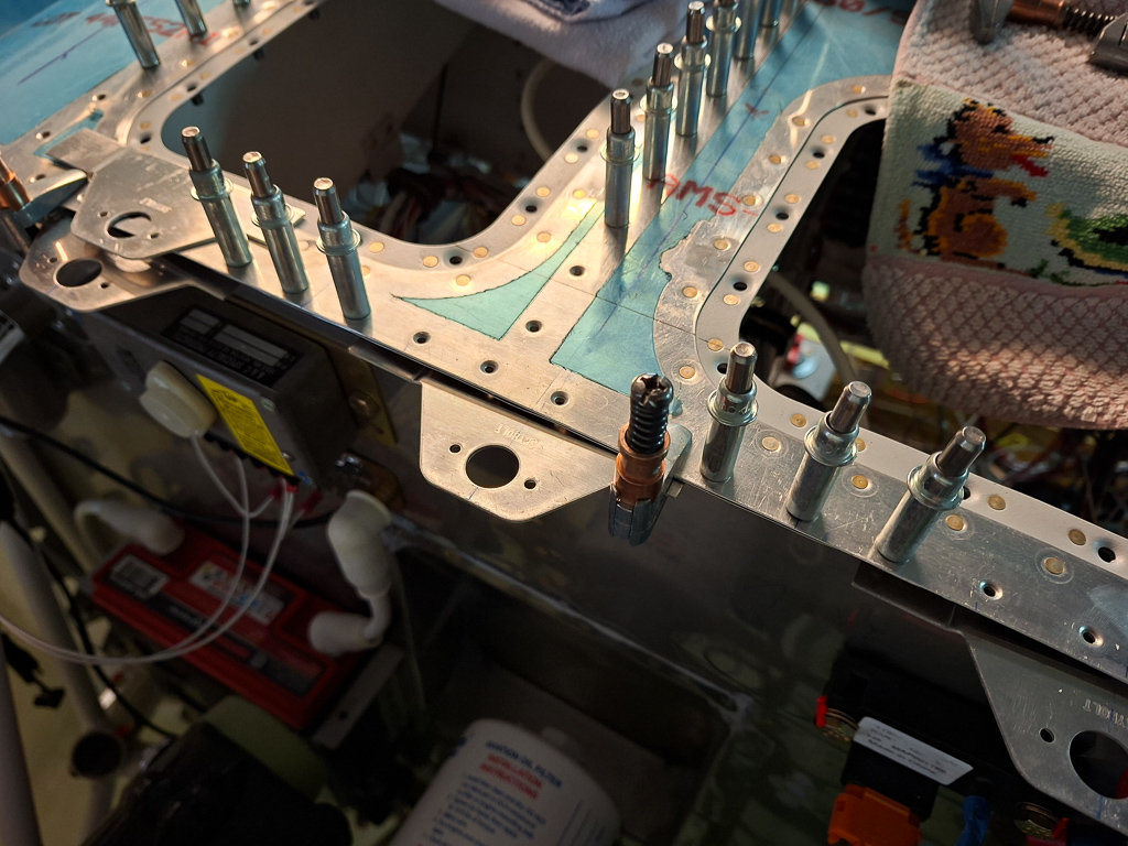
Moving along one by one.
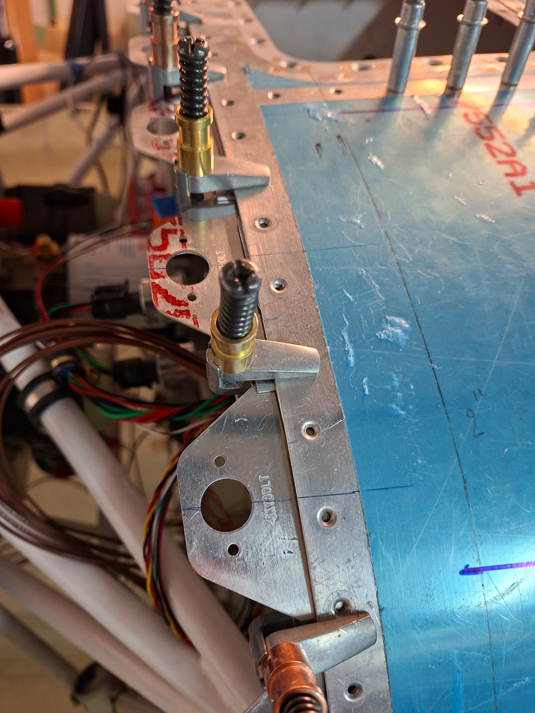
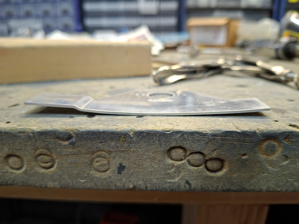
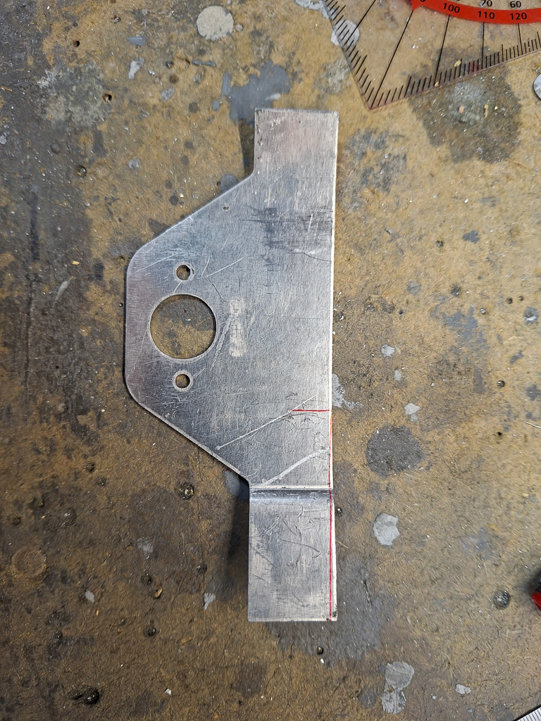
The flange at the bending point of the fuselage needs some special attention. There is an 8 degree tilt above the longerons. To make sure you have sufficient edge distance at the rear side of the flanges, it's required to cut the back side of the flange at the point where the fuselage bends. Illustrated in the image below by the red line in the bottom
All flanges drilled.
I also positioned FSF-L and -R but didn't drill those yet. I want to decide on the horizontal cut line later on during the top cowling cutting process.
At this point, I'm ready to cut back the top fuselage. The clecoes create an additional difficulty for fitting the top cowling : I am not able to rivet the flanges on. Rivetting the flanges on means installing the full top fuselage skin and I can't do that yet as I still have a lot of electrical wiring to do.
In the end, I clecoed most of the clecoes from the other side where I could. That way, I can at least lay the top cowling on the edge again and remeasure my cut line. Once the initial cut is made and I'm getting closer to the edge, I can place the clecoes on top again.