Before cutting, I came up with another idea of double checking the alignment of the spinner.
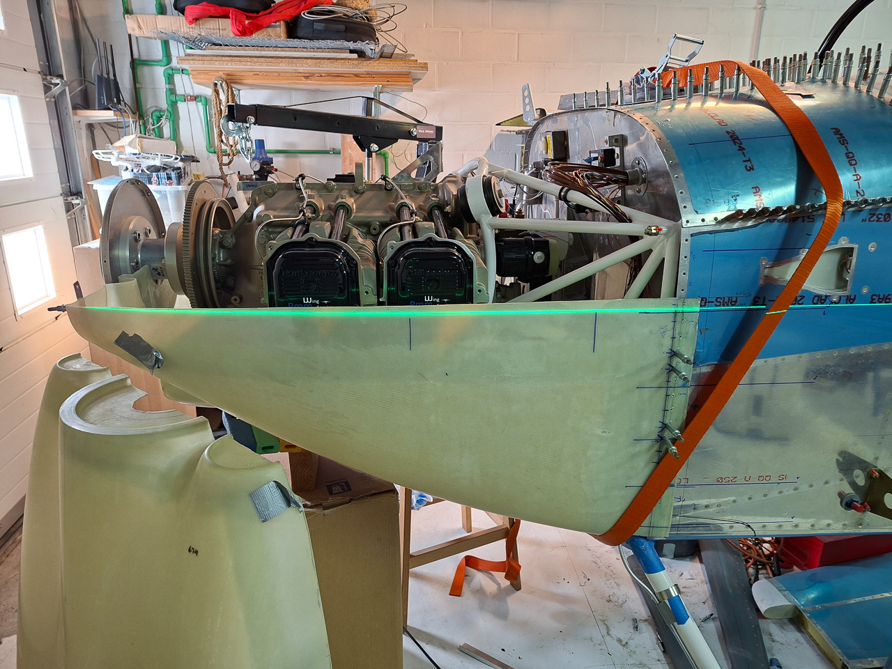
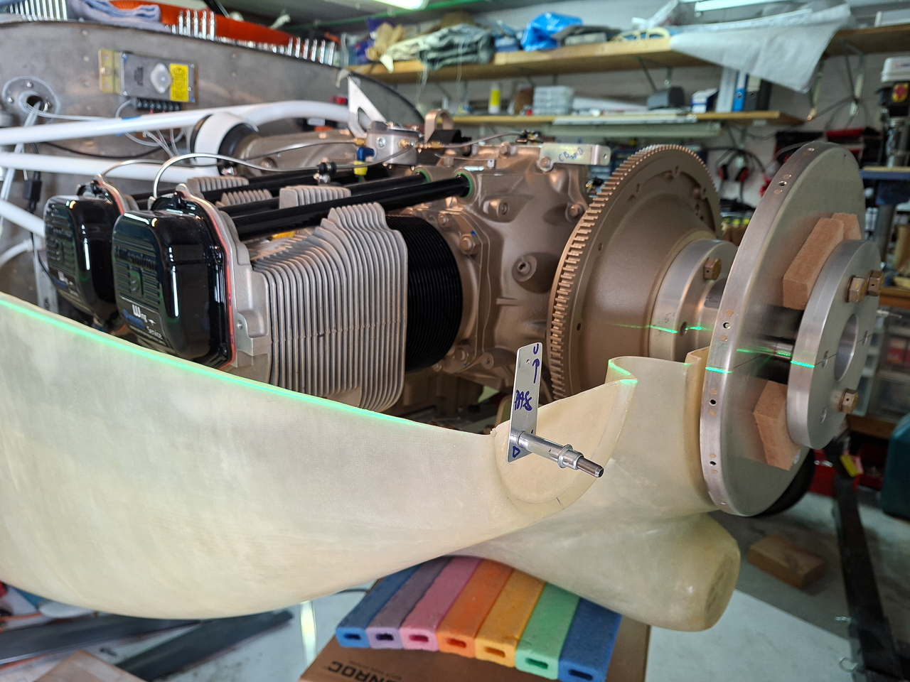
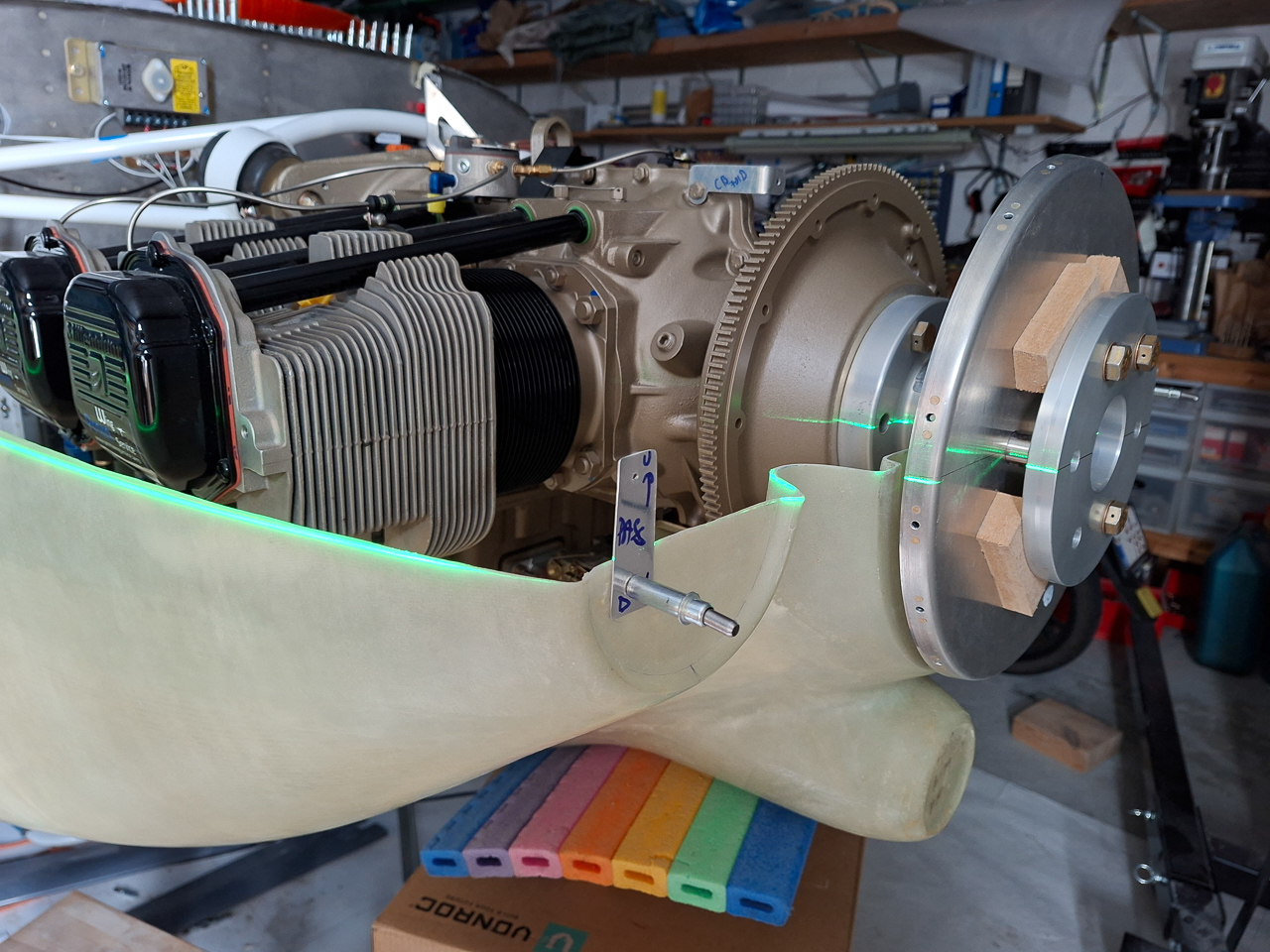
I took out the laser level again did the same leveling as for the horizontal split line aligning the laser with the front forward tip.
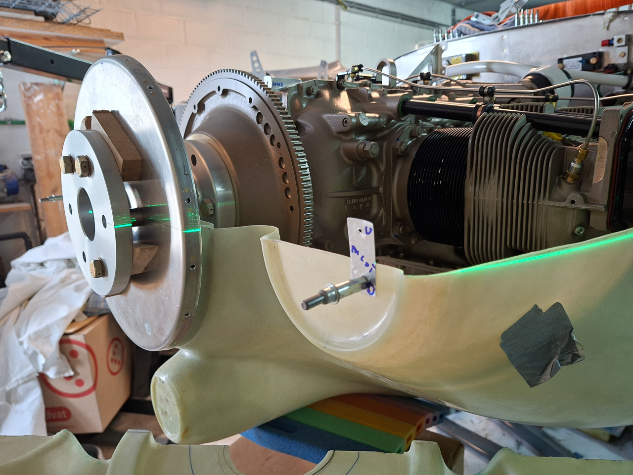
I had drawn the middle line of the spinner back plate on both the spinner back plate and the forward crush plate.
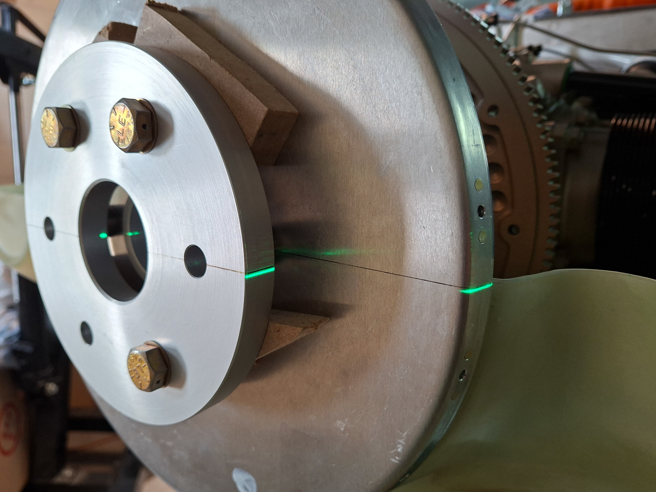
As I move the laser more forward, the green line projected on the spinner and crush plate as well.
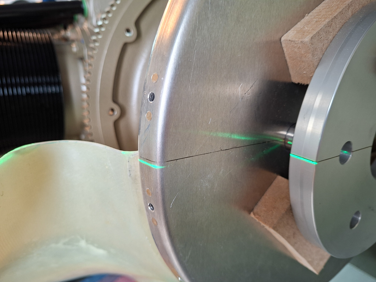
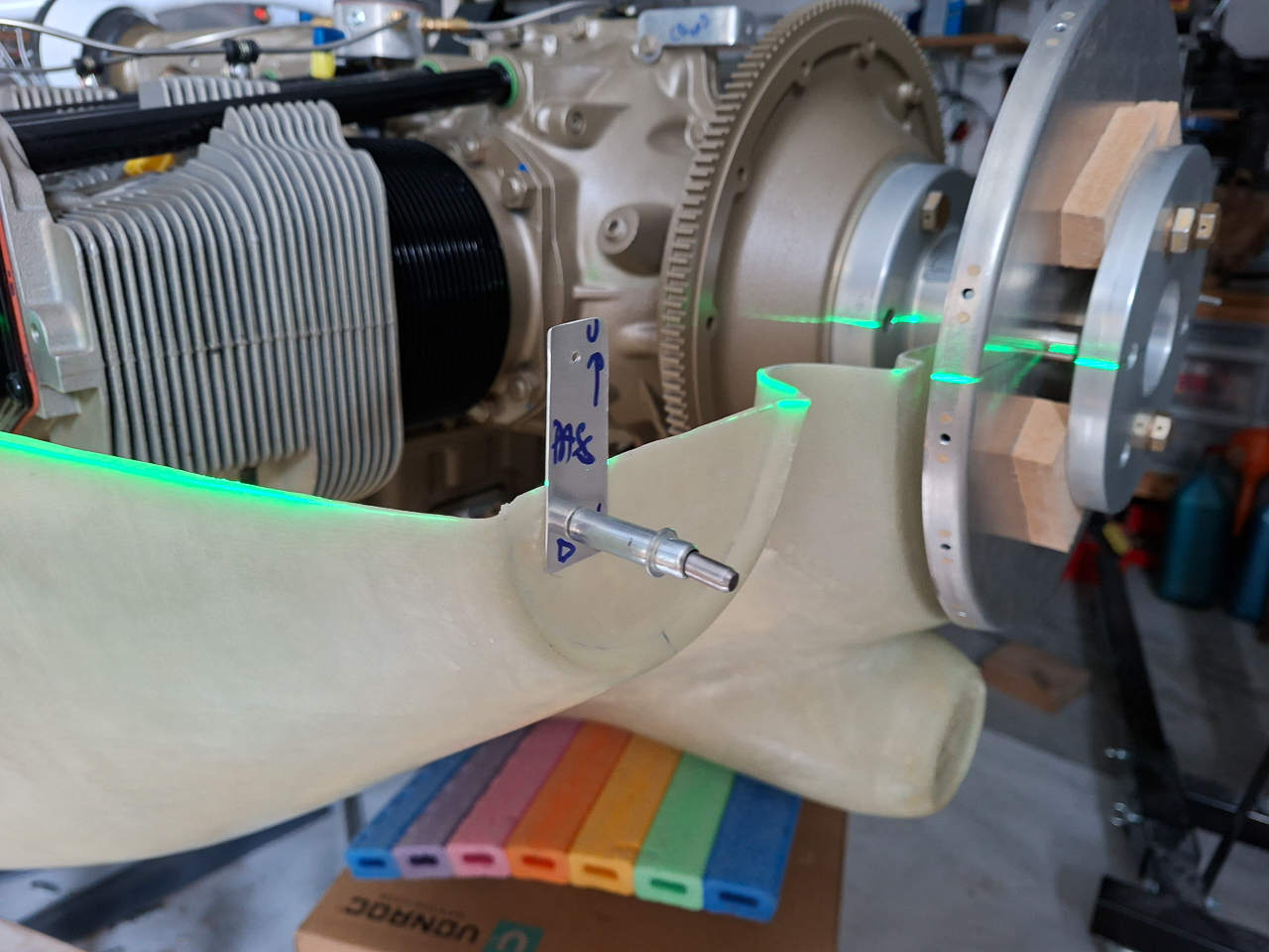
As you can see in the image below, the line aligns nicely with the middle of the spinner.
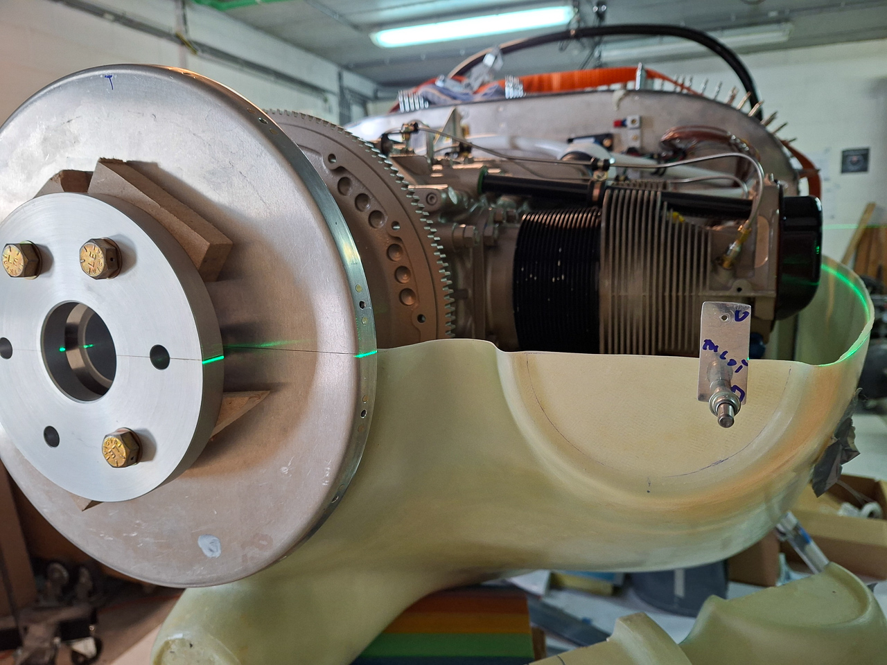
I still find it a bit strange that the level line moves down a bit towards the end. The longerons are level and the laser aligned with the front. Yet the line moves downward towards the back.
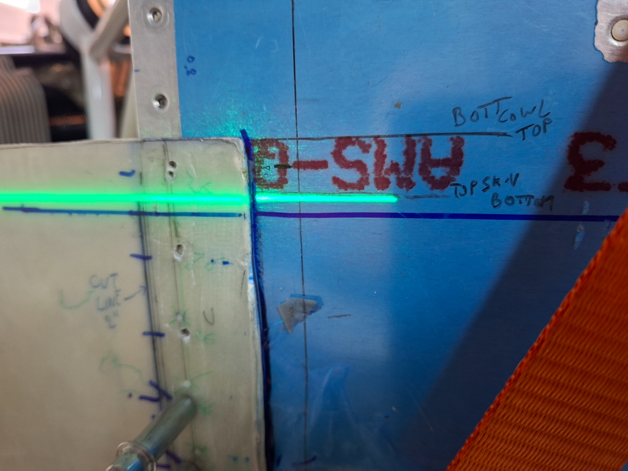
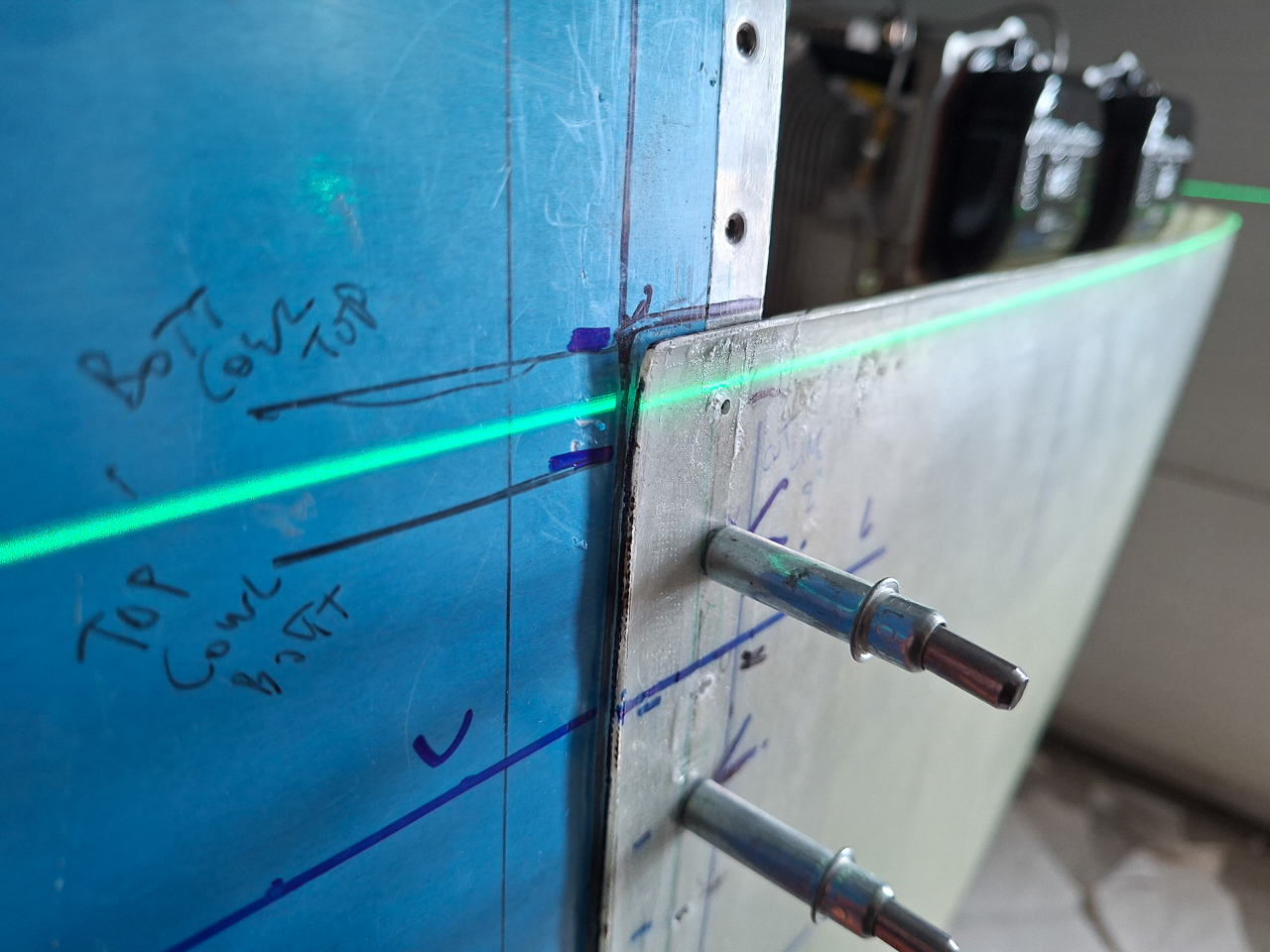
I marked the location on the side of fuselage. This line will be the top line of the lower cowling, so this is where the intersection flange brackets will be positioned on.
Did the same exercise on the passenger side.
Good alignment here is well
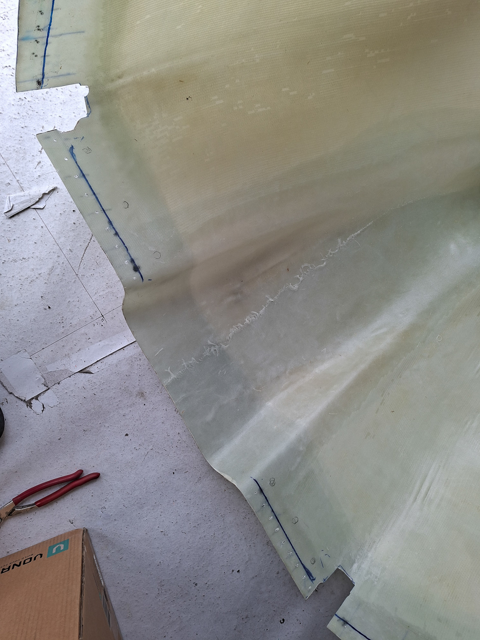
Marked the location of the green line on the passenger side as well. After removing the bottom cowling, I compared the location relative to a rivet near the point where the firewall bends foward. The measurement was nearly the same left and right. This also means the cowling is well aligned and in symmetry.
And then, finally I took it off and have it ready for cutting.
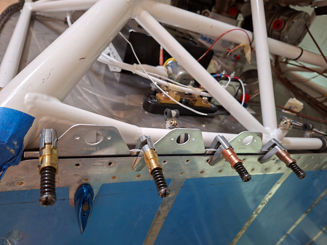
Another thing that needed to be completed before cutting was the positioning of the lower and side Skybolt attach plates.
There are 3 fasteners left and 3 on the right side. The spacing between the center of the larger holes (where the Skybolt Locs will be placed) is about 3 1/2 inch.
This is a guideline and you can play with the position as needed. The position of the firewall rivet holes sometimes falls right on the edge of a plate. You can not make them all aligned so that edge distance is achieved on all of them. In my opinion it's probably impossible to achieve that. If you really want that, you have to move the position of certain plates. That would mean that some fasteners will be more than 3 1/2 inch and some less. This would make it visually very unpleasing. I read multiple people mentioning the same story.
Position them as good as you can and play with the spacing but keep the spacing equal.
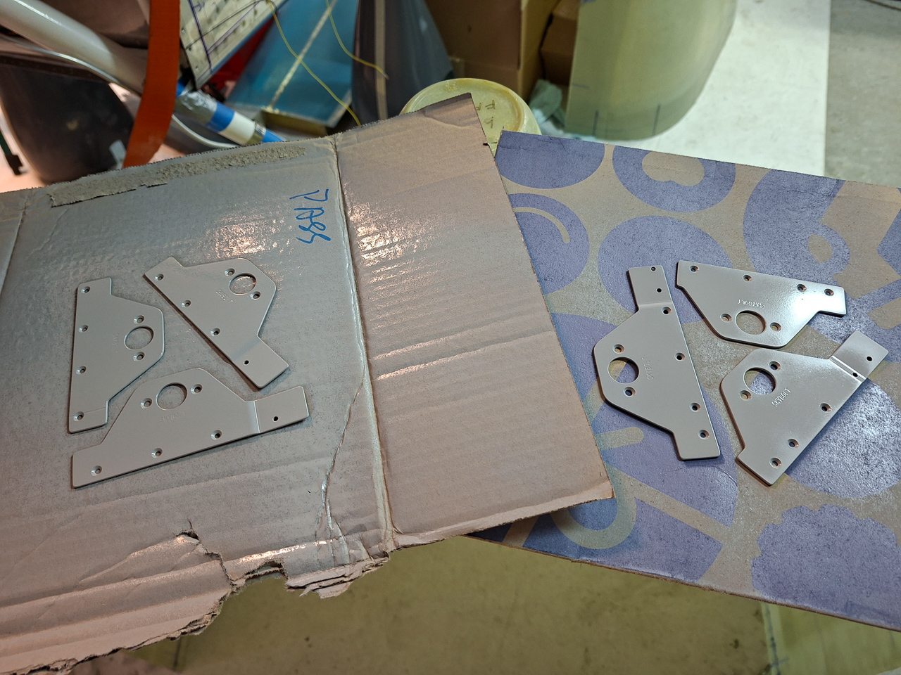
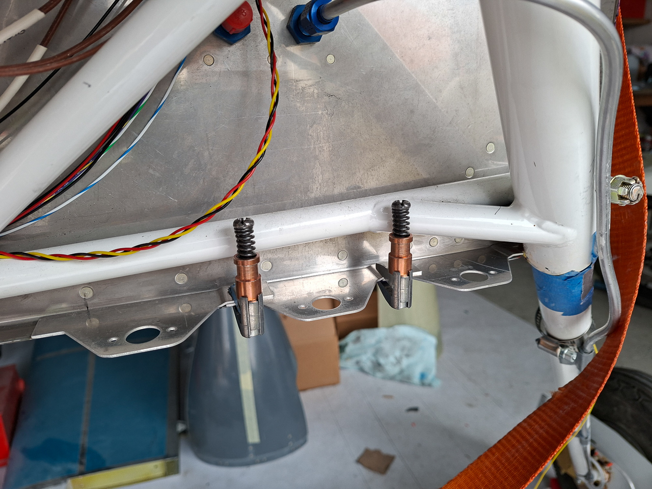
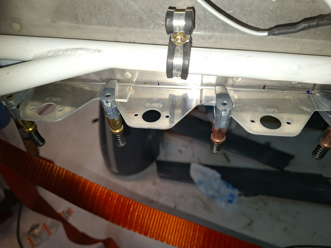
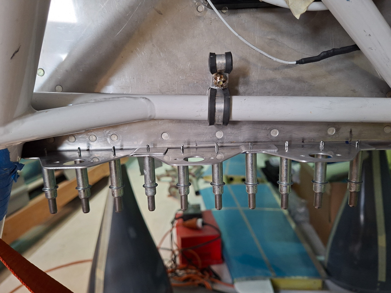
Below are my passenger side bottom brackets<.
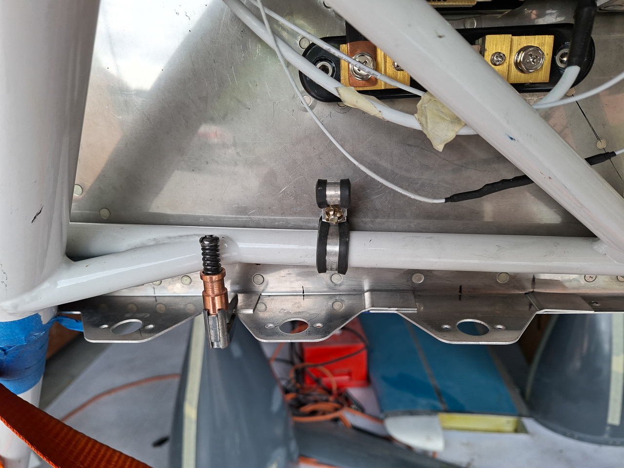
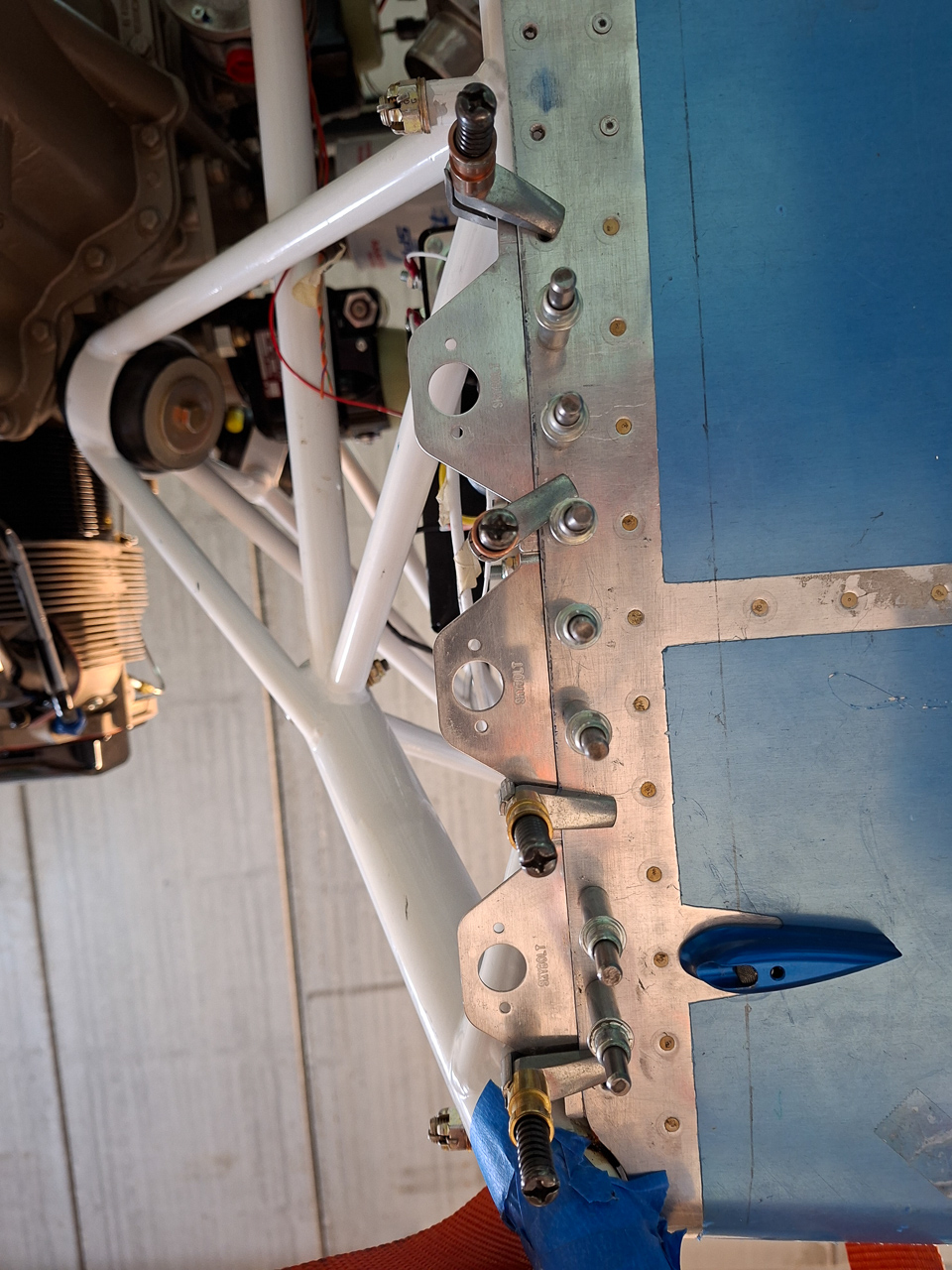
These are the pilot side brackets. On both sides, verify that you can reach in to set the rivets near the landing gear leg.
The distance between the firewall eddge and the front of the bracket should be between 0.230 and 0.250. That is what the manual tells you to do.
I would not do that if I were you, at least, I didn't. If you measure 0.230, the edge distance of the drilled holes is insufficient. It would be even worse if you use 0.250.
I brought this down to 0.200 and that works well for having sufficient edge distance.
Cleco clamps work well here order to align the brackets and measure the offset distance.
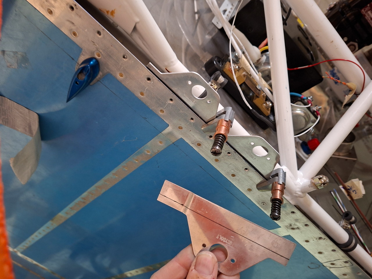
You will need to cut away some flange edges where the bracket overlaps. Most of them need to be shortened on the unbent sides to lay nicely at the wiggle of the other bracket.
On some of them you also need to cut from the top flange if a rivet hole is really on the edge of the bracket.
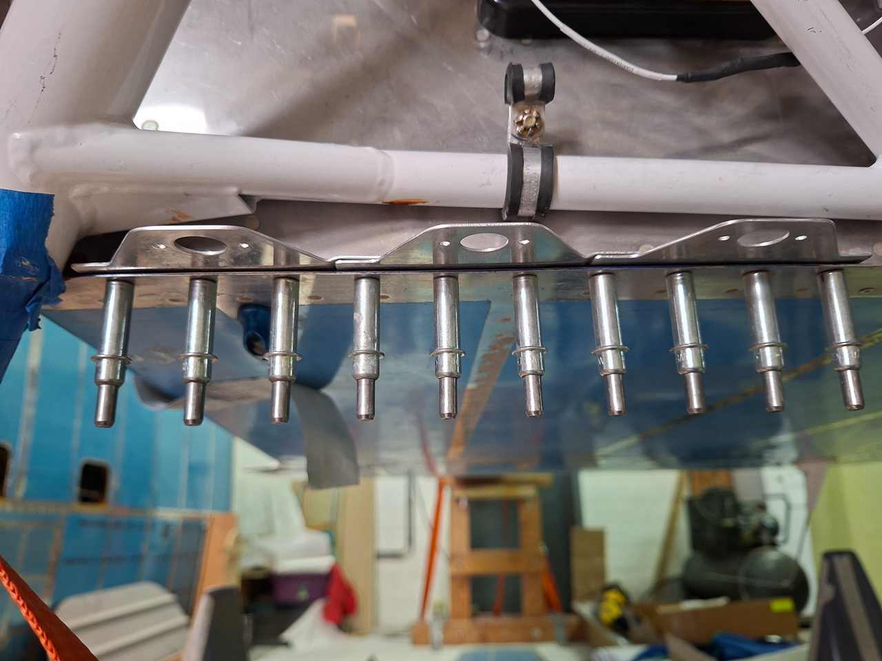
In the next image, I have drilled the 3 of the brackets on the firewall edge.
I did make additional hole when a hole was near the edge of a bracket. This will give extra strength.
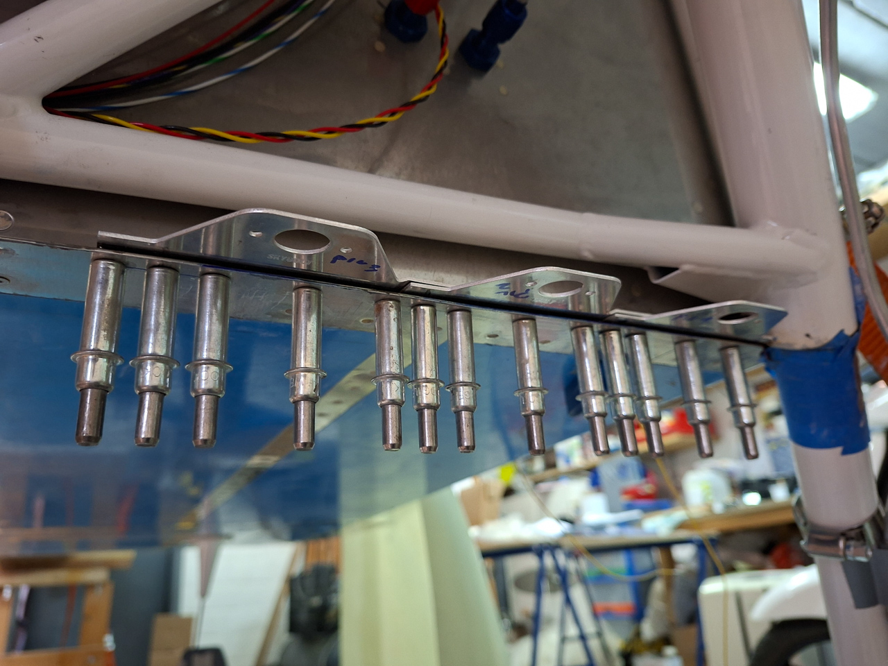
You can see what I mean in the image below. on the overlap, on the right side of image, the hole is near the edge. So I drilled an additional hole in between the 2 existing ones.
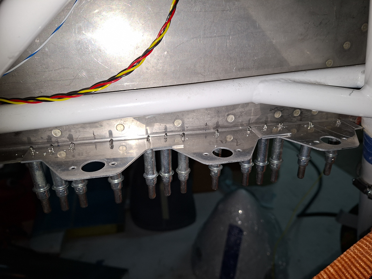
Also drilled the passenger side. No need for additional holes here.
I bought this primer spray cans. They only had them in white and gray as primer and I think the gray will be visually ok near the silver colored firewall.
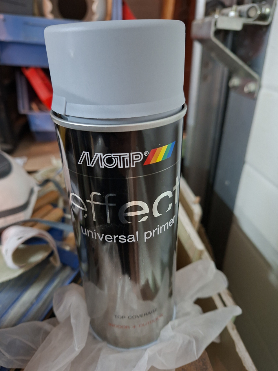
Countersunk the plates and applied the primer.