For a long time, I was skeptical about hanging the cowling, influenced by other builders who described it as the most dreadful part of plane building. The process involves fitting, cutting, hanging, and repeatedly filling pinholes with epoxy, sanding, epoxy, sanding, epoxy, sanding, epoxy, sanding, and more sanding—a truly memorable challenge. With this in mind, I began researching how to approach the cowling.
My cowling is not the standard Vans cowl but the Sam James Long cowling by James Aircraft. I also bought the induction kit that goes with it.
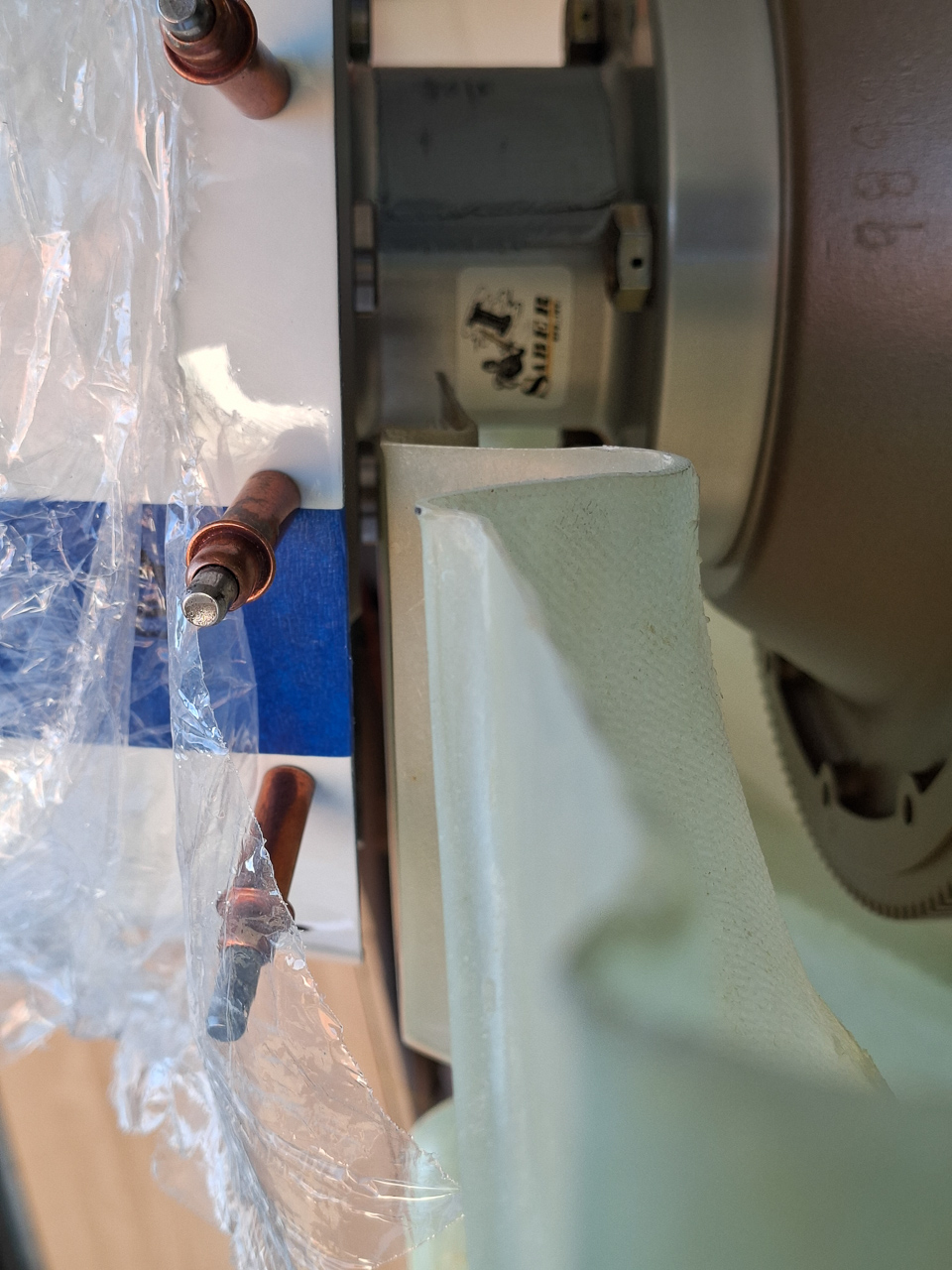
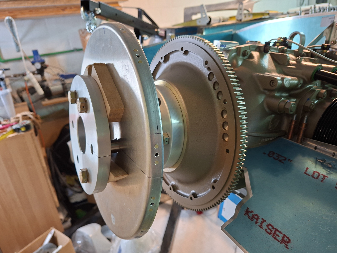
I have a 3 blade catto propellor which requires a 4" Saber extention (Extension 4 in. long, 7 in diam, 12-hole, SAE-2, 1/2E. Crush Plate) in combination with the Sam James cowling.
I have read the manual of the Sam James cowling but I found it rather cryptic and not easy to ready for a new builder. I also had purchased the CLoc Skybolt fastener system , which has its own manual. After reviewing the vans instructions on their standard cowl, the Sam James manual and the skybolt manual, I decided that I would go with the Skybolt approach. Their manual is great and instructions clear. Much of the work is similar. The manual of Skybolt can be found here on their website.
I also found great resources on kitplanes.com. More in particular a series of articles written by Larry Larson also known as WireJock - a well known contributor - on the vansairforce website. The articles explain the Skybolt installation approach step by step by using a propellor jig.
Read the 2 most important articles here: part 1, part2.
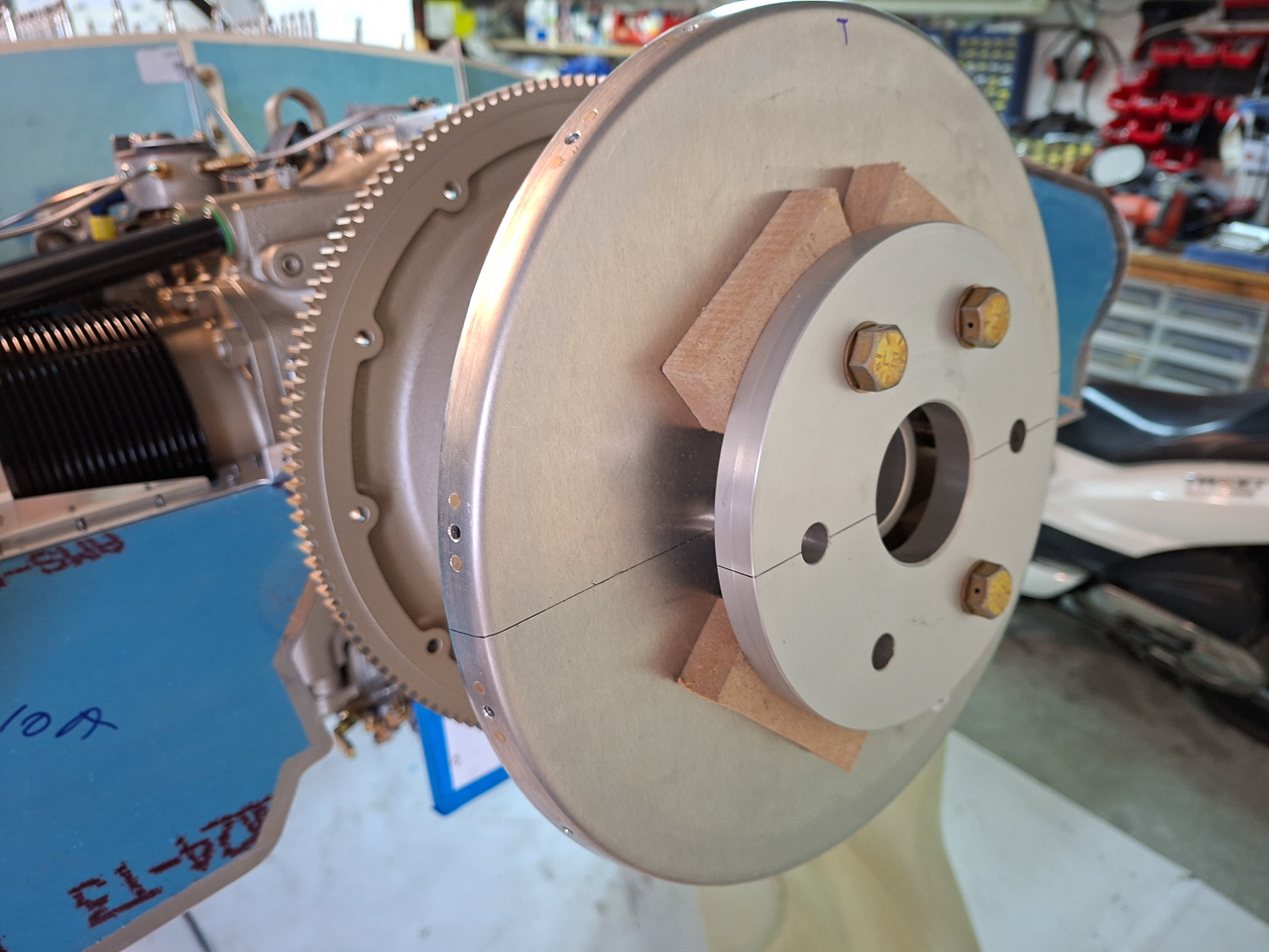
This is much more compact than having the propellor in the way. As the spinner is drilled by Catto, I can just cleco them with #30 cleco's it in the nutplates on the side of the back spinner ring.
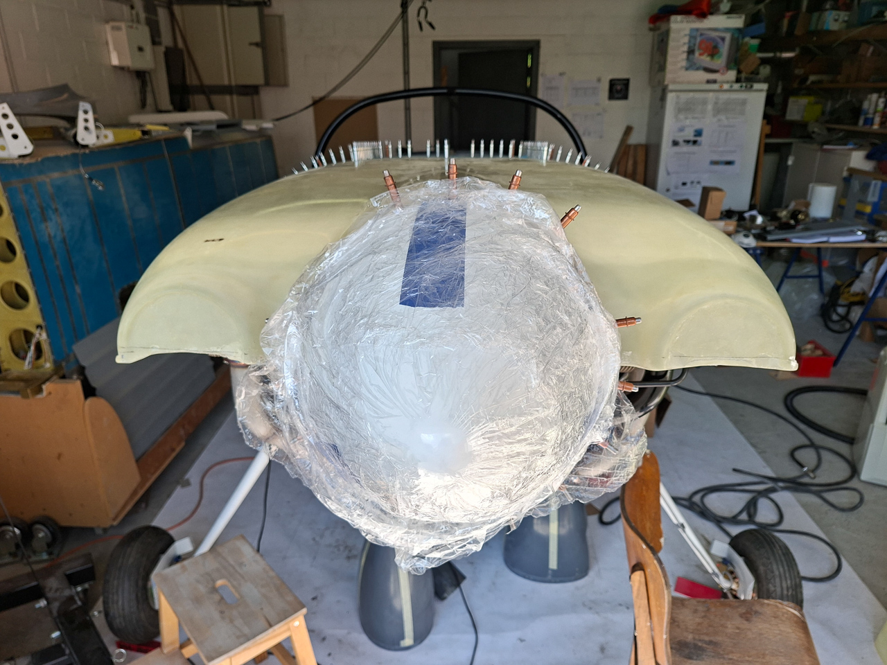
I did this in the picture below and couldn't resist placing the top cowl over the engine. It looks really nice.
I also used this opportunity to draw a center line on top of the top cowling by using the middle of the fuselage as a reference point and the middle of the spinner. A double check can be done to assure left and right are at the same distance from a "level" point. (put a level on top of the spinner and measure from the level to the top of the air intake rings).
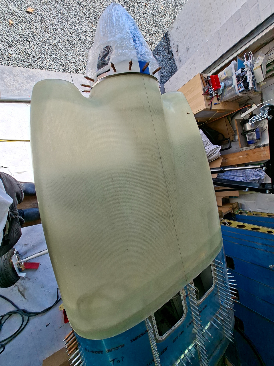
Another shot from the front.
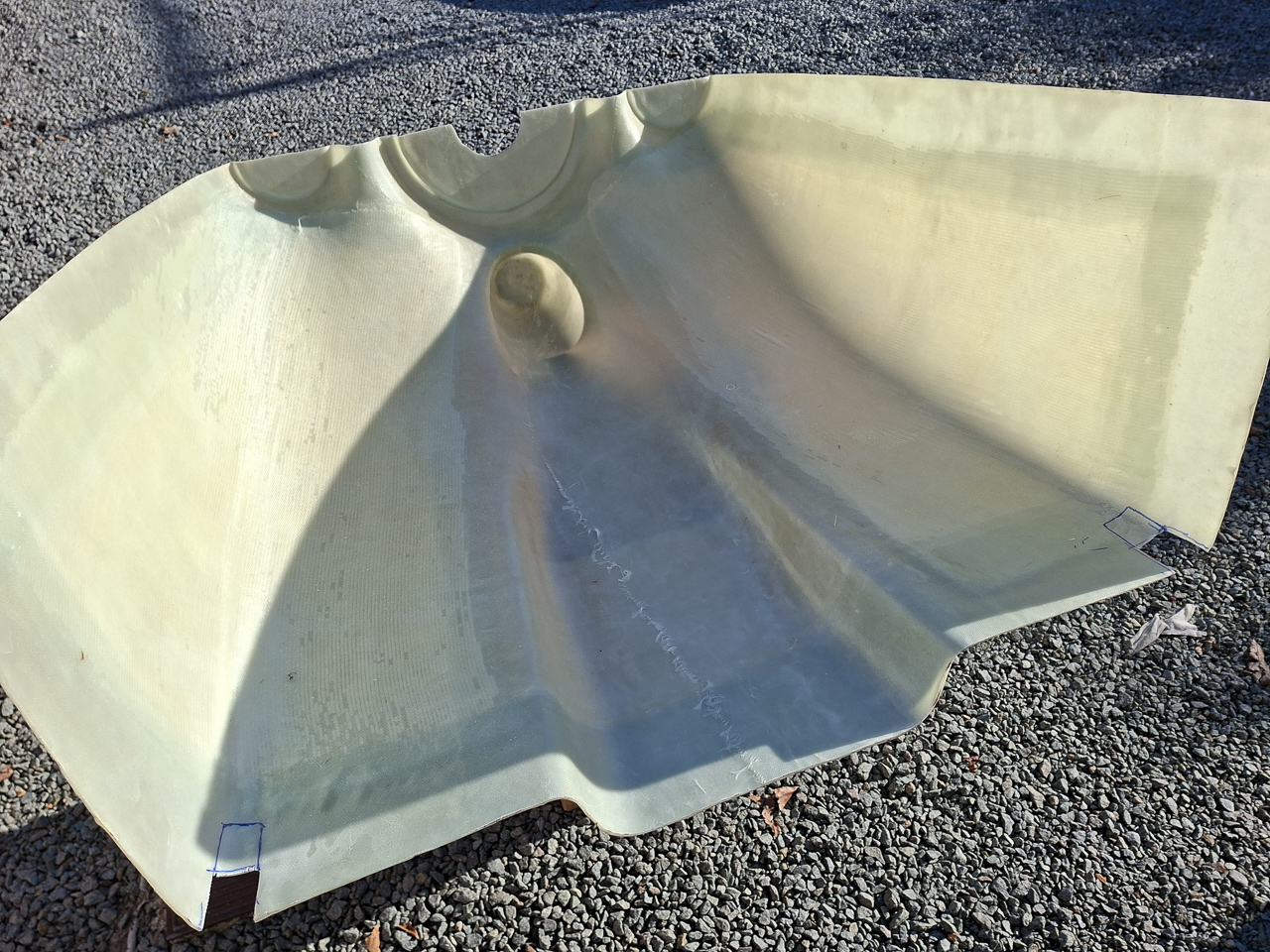
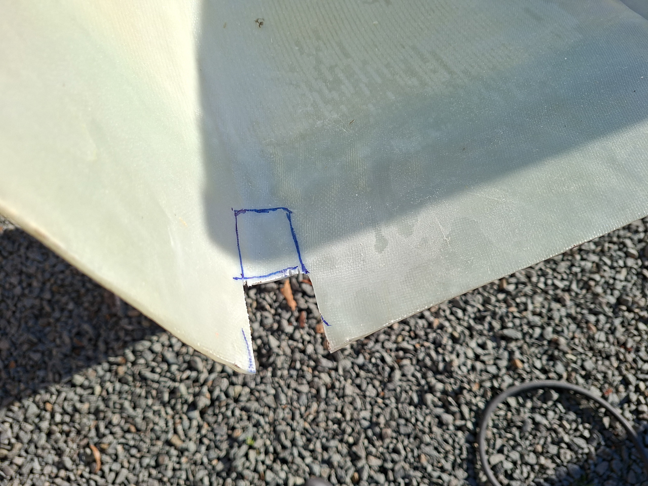
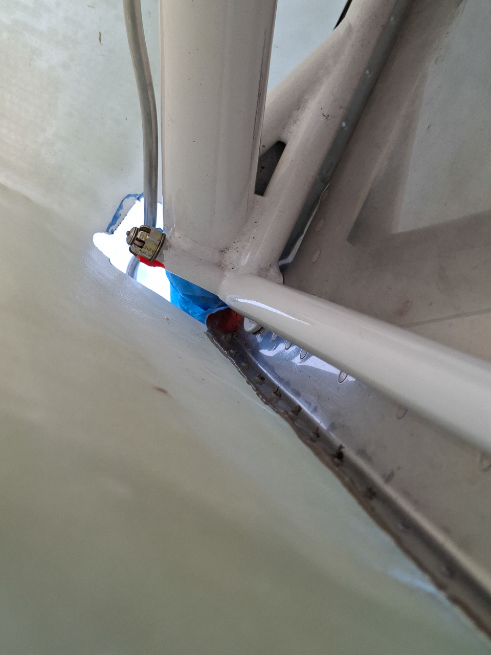
Next I cut some holes in the lower cowling in order to clear the landing gear legs. This is a repetitive process of checking and cutting more. The brake lines are really annoying at this point as they kind of sit in the way all the time. In order to slide the cowling under the spinner, you need to move the whole cowl a bit more backwards than it will be in it's final cut state. My cut out may be a little to large in the end but this will be covered with gear fairings and I will probably add some new epoxy when all is ready to make this hole as minimal as possible.
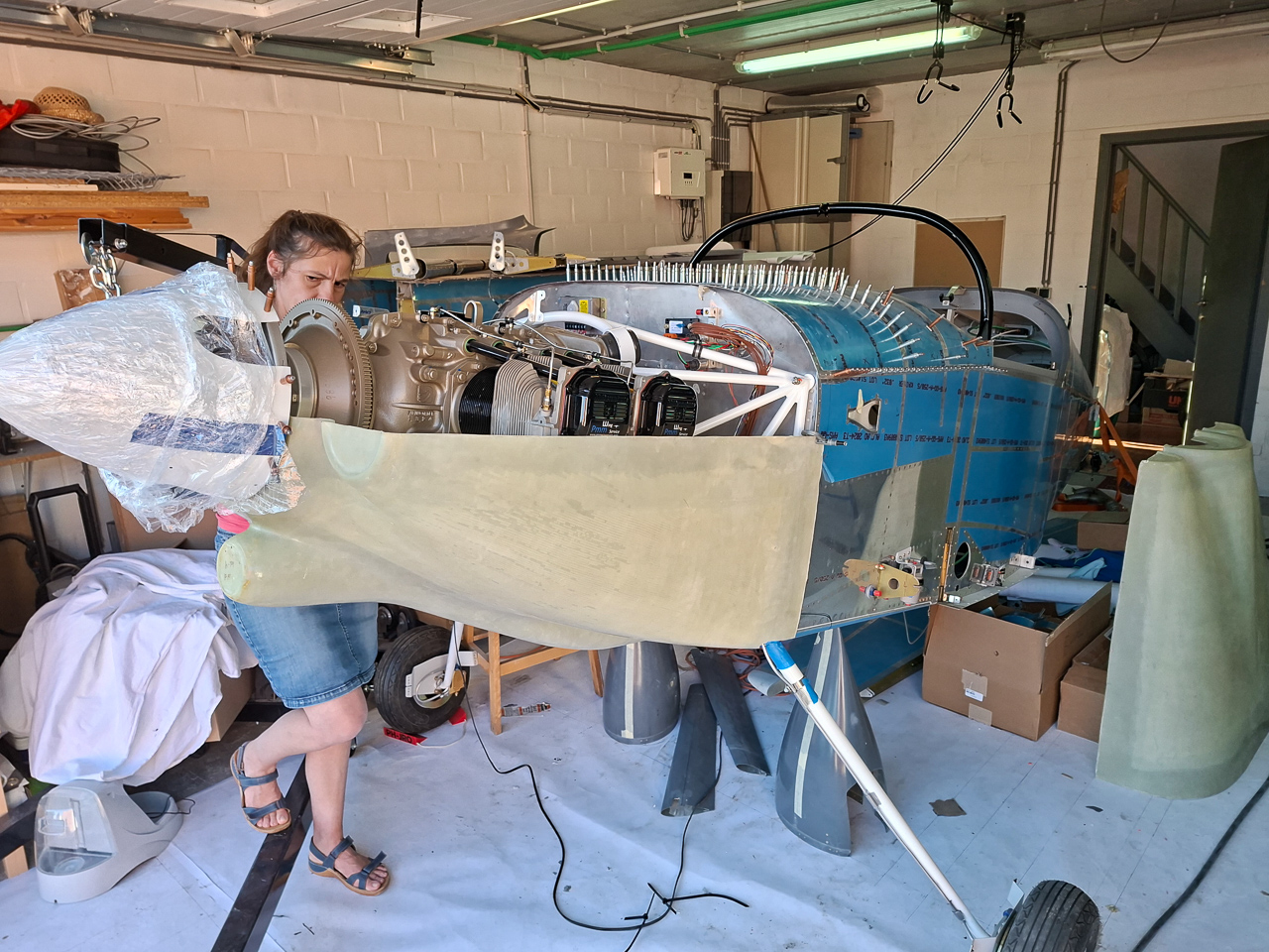
Cindy helped to hold the bottom cowling each time I got it on and off. It's very difficult if not impossible to do this on your own.
As you can see here, the front hole is slightly oversized but the cutout is really needed at this point to clear the brake line when sliding the cowling from underneath the spinner.
I'm just holding the cowl by hand at this point, but the gap shown in this image is what you will be looking at during every trial fit. The distance between the bottom and top of the cowl needs to be equal at about 0.25" all around. (left side, right side, bottom and top).
The cowl is obviously too low at this picture. The transition of the spinner to the bottom cowl is equally important.
Starting to get the picture ? Precision and patience are going to be crucial for this high-accuracy task.