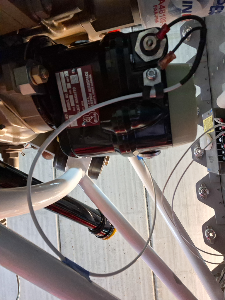
Today I worked on the P-lead wiring.
My magneto's are both old style Champion Slick Magneot's with impulse coupling.
Both mags have the impulse coupling which retards the spark upon start of the engine for easier starting. Usually only 1 magneto has the impulse coupling and in that case the starter swtich needs a jumper placed on the ACS-510-2 starter switch.
This jumper would ground (disable) the magneto without the impulse coupling during start so that they don't work on different timings which could be disastrous for your engine.
In my case it's easy, both have an impulse coupling so both mag's must be active and used during cranking of the engine at startup. No grounding on startup in my case.
That makes the wiring on the ACS-510-2 starter switch also a bit easier.
Some theory first :
A magneto is always hot ! Meaning it's always working and providing a spark when the propellor is turned and the magneto spins.Even with the master switch off...
The magneto works independently from the electric system and provides it's own power. Accidentally spinning the propellor could fire up the engine and cause mortal and disastrous consequences for people in the area of the propellor.
To provide a safety mechanism and disable the magneto when we are in the hangar, we GROUND the magneto's.
This is done by a wire that runs from the starter switch to the P-Lead stud on the magneto. It literally attached the P-lead to the Ground path of the aircraft.
If the magneto is attached to Ground, it is unable to produce a spark and as such cannot fire the engine.
The reason doing this through the ACS-510-2 starter switch is because we need this grounding also during our run-up run on the ground where we test one by one the left and right magneto activity.
When we place the key on L for testing the left magneto, internally in the switch, the right magneto P-lead is grounded and the other way around.
With the starter swtich to OFF, both P-leads wires are connected to Ground.
So I needed to make 2 wires that run from the starter swtich to each respective magneto P-lead stud.
This is supposed to be shielded wire. The inner conductor is the actual P-lead grounding path, the outer shield is connected to the ground tab of the magneto housing.
I started by stripping a couple of inches of the outer insulation exposing the shield and winding it up into a wire. You need sufficient length on the magneto side to split these 2 ring connectors on their respective stud. So make sure you have enough length available on both ends.
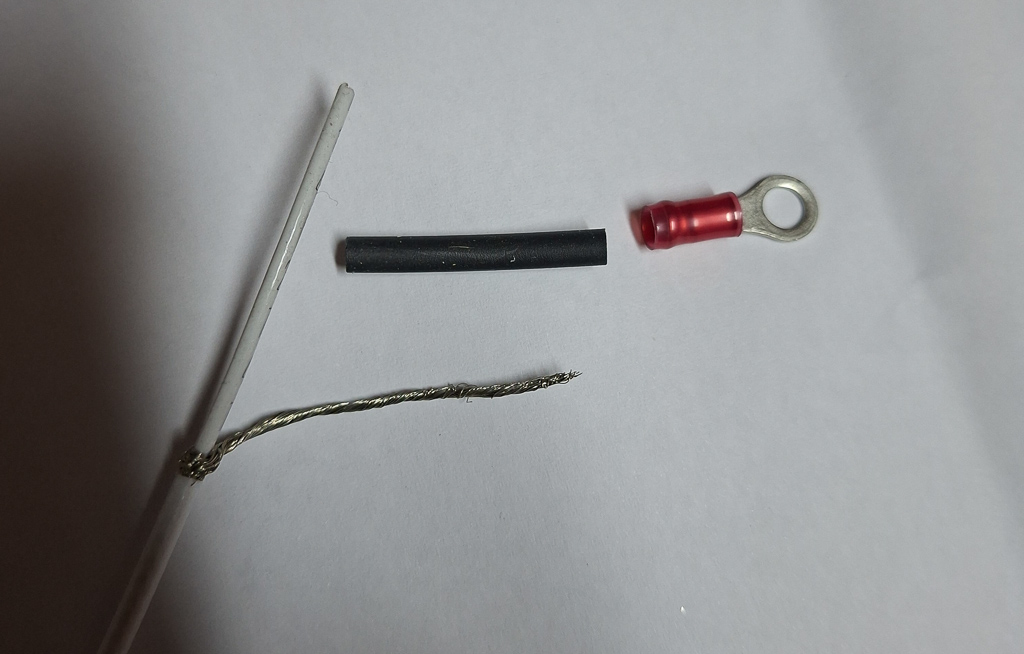
Then I crimped the ring terminals to the inner conductor and to the shield wire. Don't forget to put heat shrink on there before you crimp the wire.
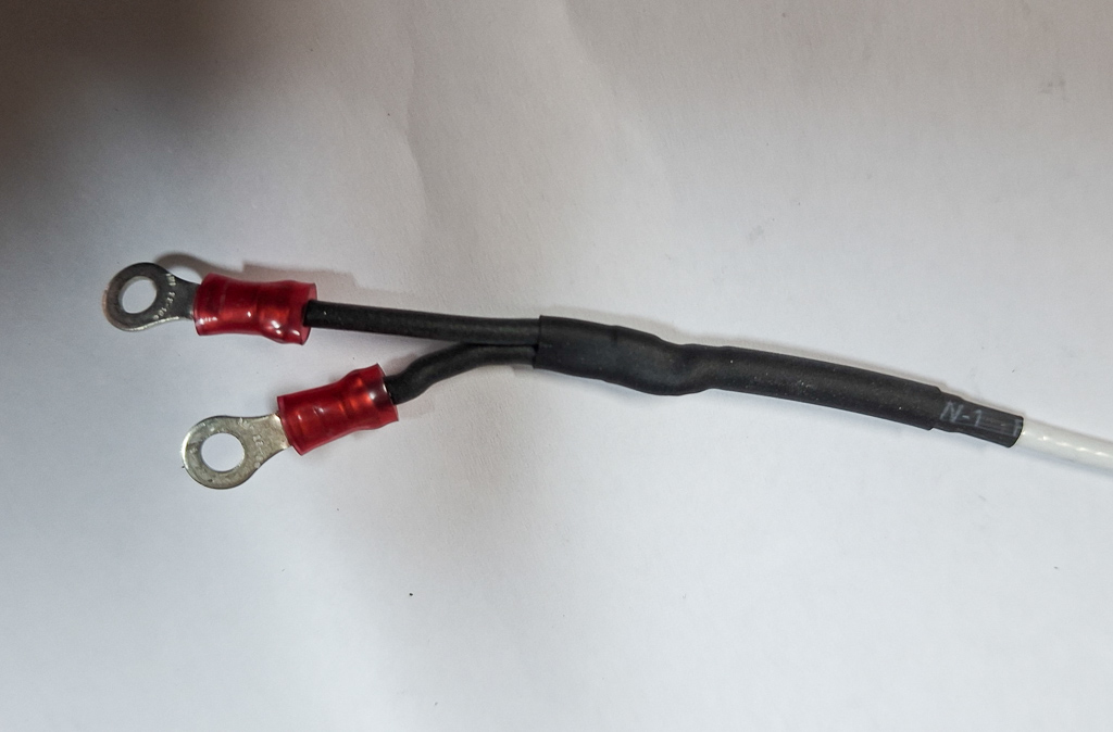
A second piece of heat shrink of larger size will cover the junction and stiffen and protect the wire.
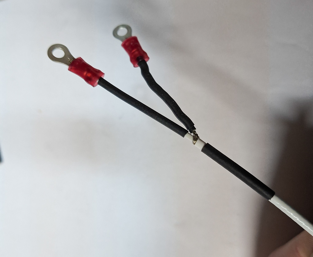
In the picture below, the heat shrink is over both wires.
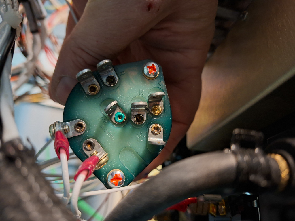
This was the status of my ACS-510-2 starter switch before additional wiring.
The lowest wire (BAT contact ) is where the switch get's it's battery power from the VPX through J10-1 (Starter contactor coil power)
The wire on the left (S contact) is the wire that connects to the S-lead of the starter contactor (which activates the coil and closes the contactor which in it's case engages the engine starter).
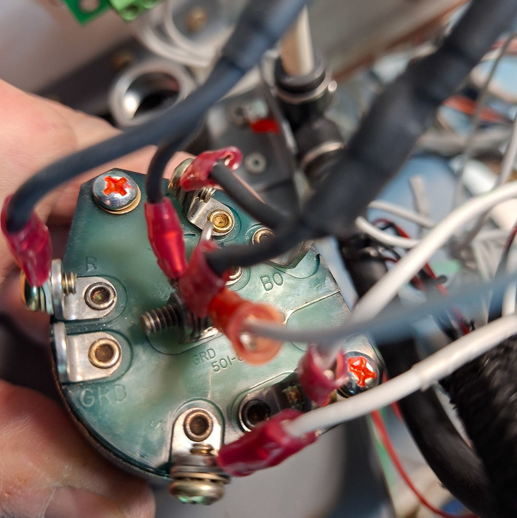
In the image below, both P-leads are attached to their terminal L and R. The Right magneto P-lead connects to the left where the R mark is, the left magneto P-lead is at the top of the image where the L mark is. In the middle GND marked tab, I connected a wire to the GND tab at the firewall and to the shields of both Mag's.
I read somewhere the shield GND actually only needs to be connected only in one direction to the magnoto ground tab. In my case I had already wired it to the magneto and also to GND on the starter switch.
It's important not to forget to pull a wire from the GND tab of the starterswitch to the GND of the aircraft. If you fail to do so, your magneto's will never be grounded when in the OFF position.
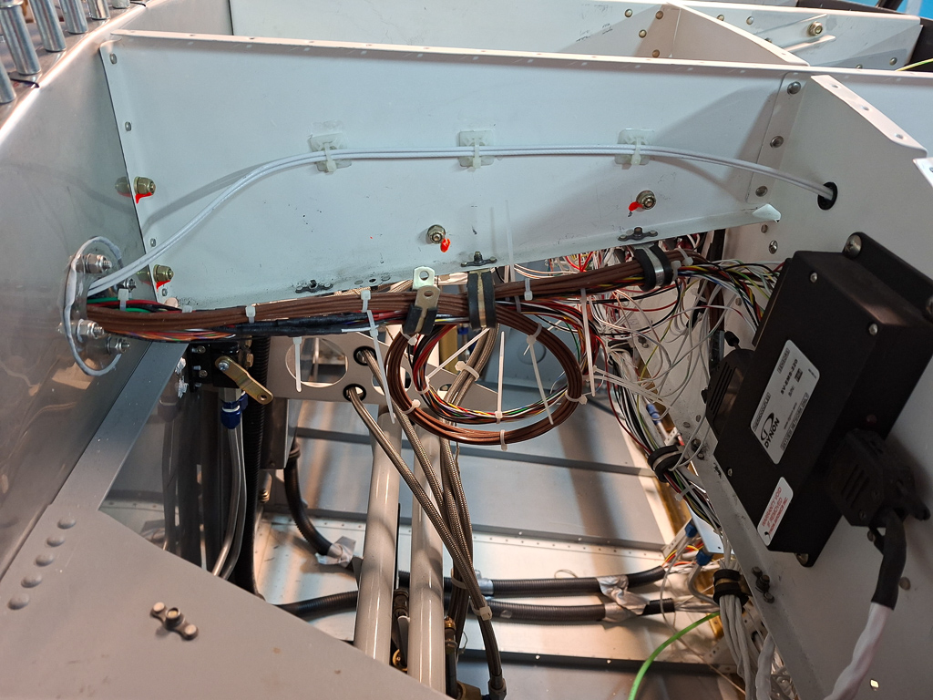
Wire routing runs through a bushing in the upper part of the bulkhead. (the white wire running from the starter switch to the upper right in the image here is the P-lead wire).
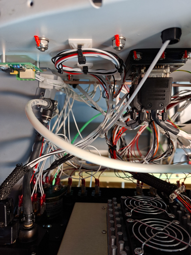
Behind that panel, I attached some ziptie bases to the rib to isolate the P-leads from the other wiring.
Here is the connection of the P-lead to the left magneto. The wire will run along the engine mount and then move down to the back of the magneto. And adel clamp supports the wire at the ground connection of the magneto and both ring terminals then turn around to the respective stud. the left one in the image is the P-lead connector, the adel clamped connection is the magneto case GND. I still have to install the sillicon boots on these.
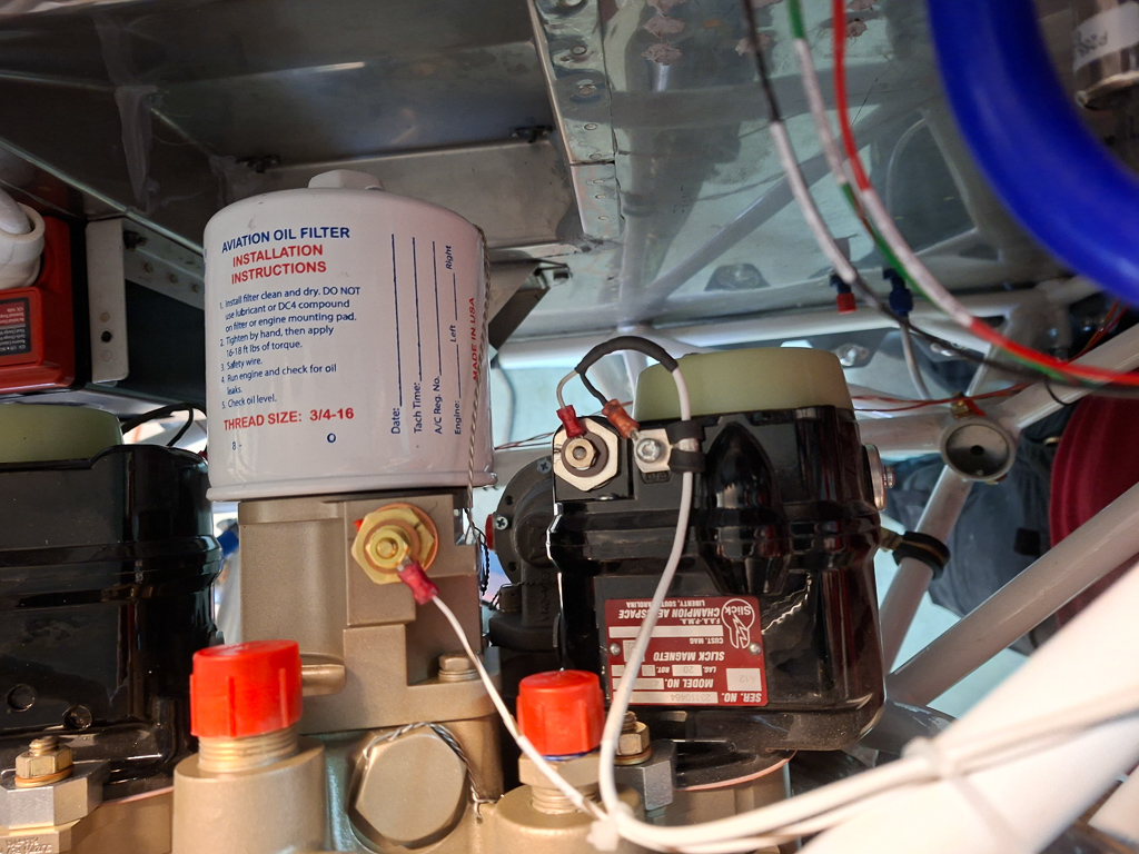
This is the connection on the right side magneto. A bit more work to install as the orientation is down on the right magneto.
Take care of the torque limits on these connections
Torque P-lead nut to 13-15 in-lbs. (found in Champion L1363-J magneto maintenance overhaul manual p 3.2.4 on page 3-2)
Attach the P-lead ground shield, if applicable, to the ground screw on the side of the magneto. Torque the P-lead ground shield screw to 18-20 inchpounds. (found in Superior IO360 install manual chapter 3 page 12, 8. ELECTRICAL SYSTEM)