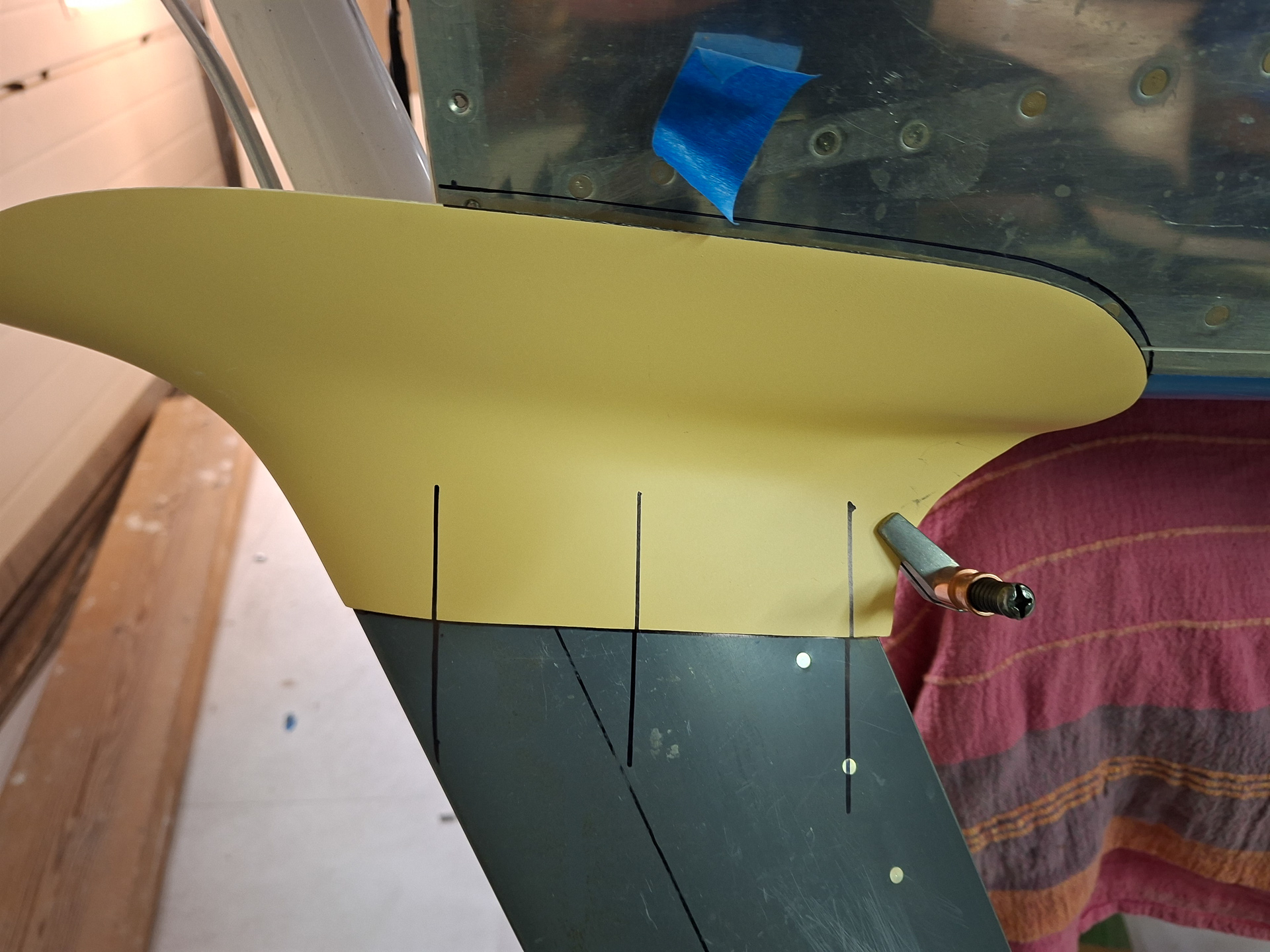
Spending more time on the wheel fairings. As you can see by the sequence number of this article in the series, this wheel pant work is taking much more time than I had imagined.
In the last session, I reclosed/epoxied the drilled holes as the rear of the wheelpant was off from the centerline. I sanded it flat again and redrilled the hole to move the tail side of the wheel pant more outboard. As you see in the image below, the offset from the previous hole is almost half a diameter.
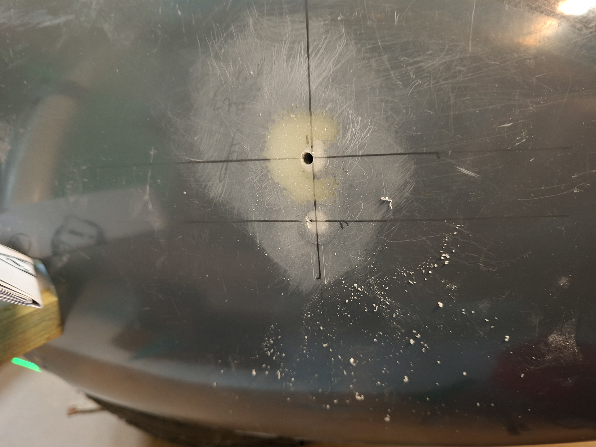
Ran a screw in and it feld the fit was right this time and also the tail lined up more accuratly.
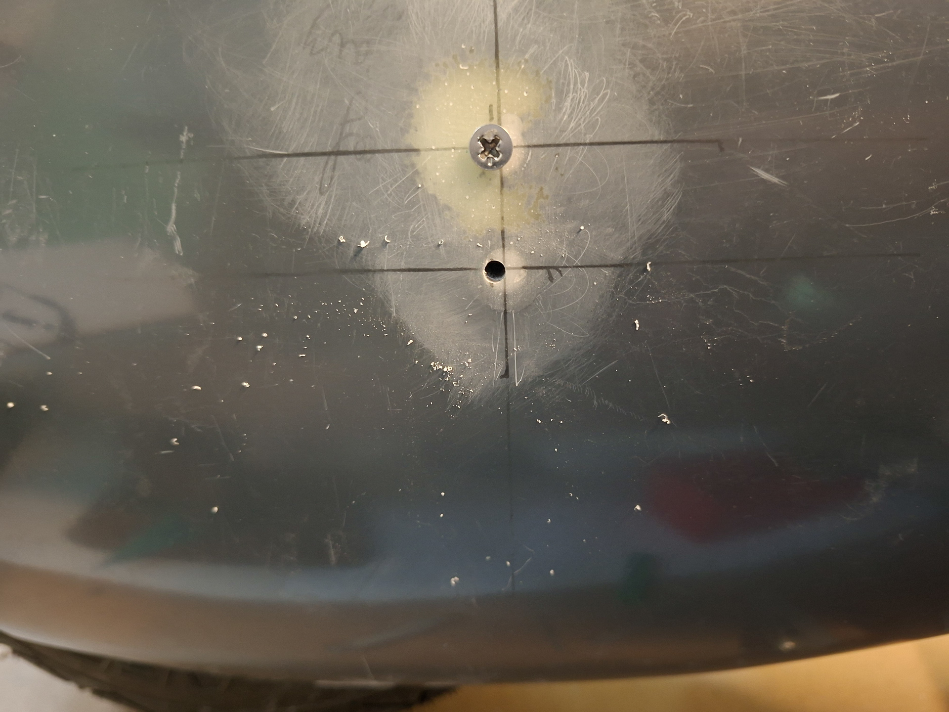
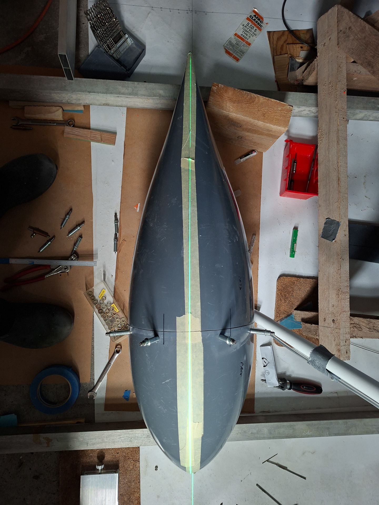
With the new holes drilled, remeasured the longitudinal lining. projected the laser through the centerline marked holes at 37.4"
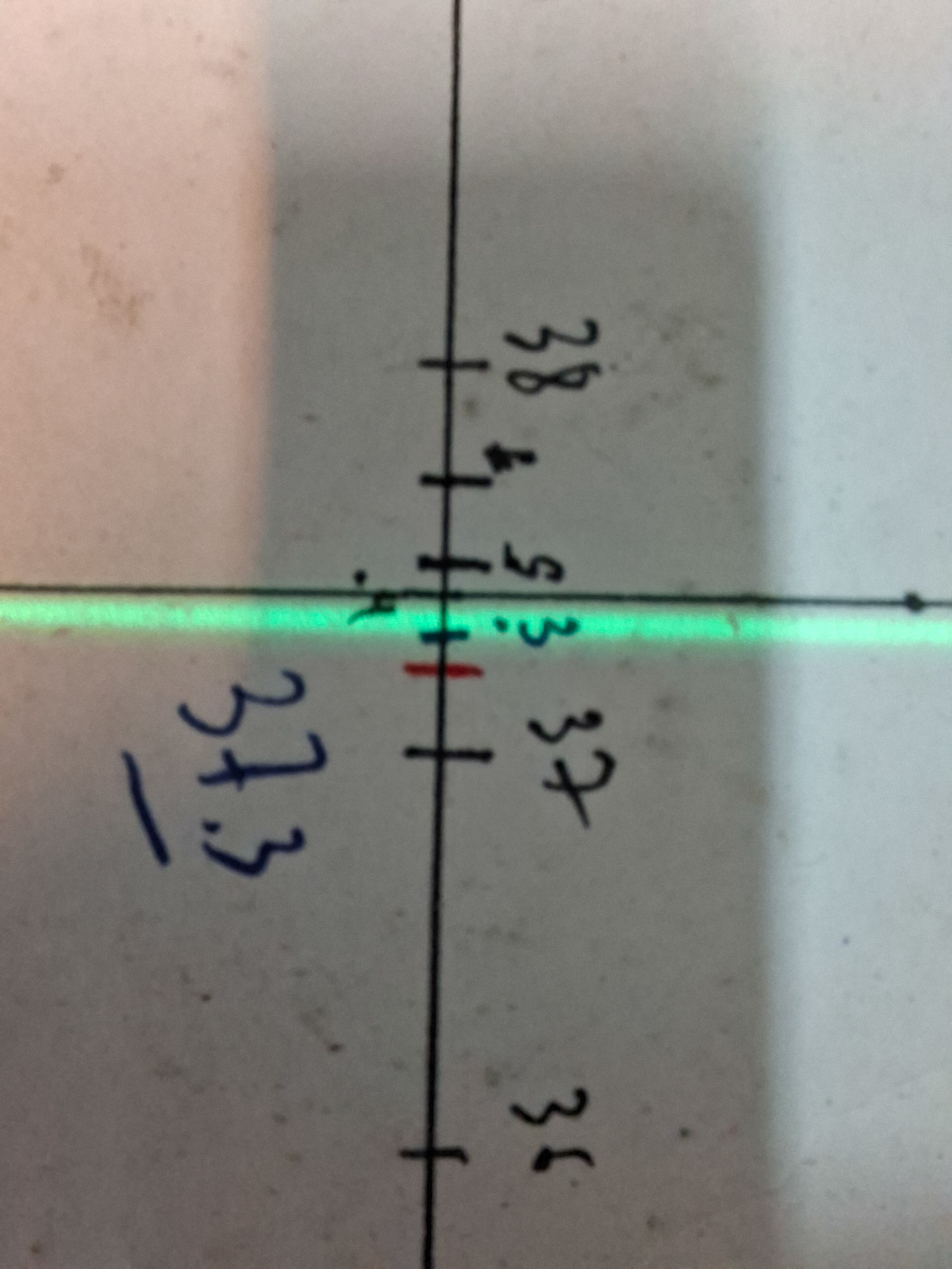
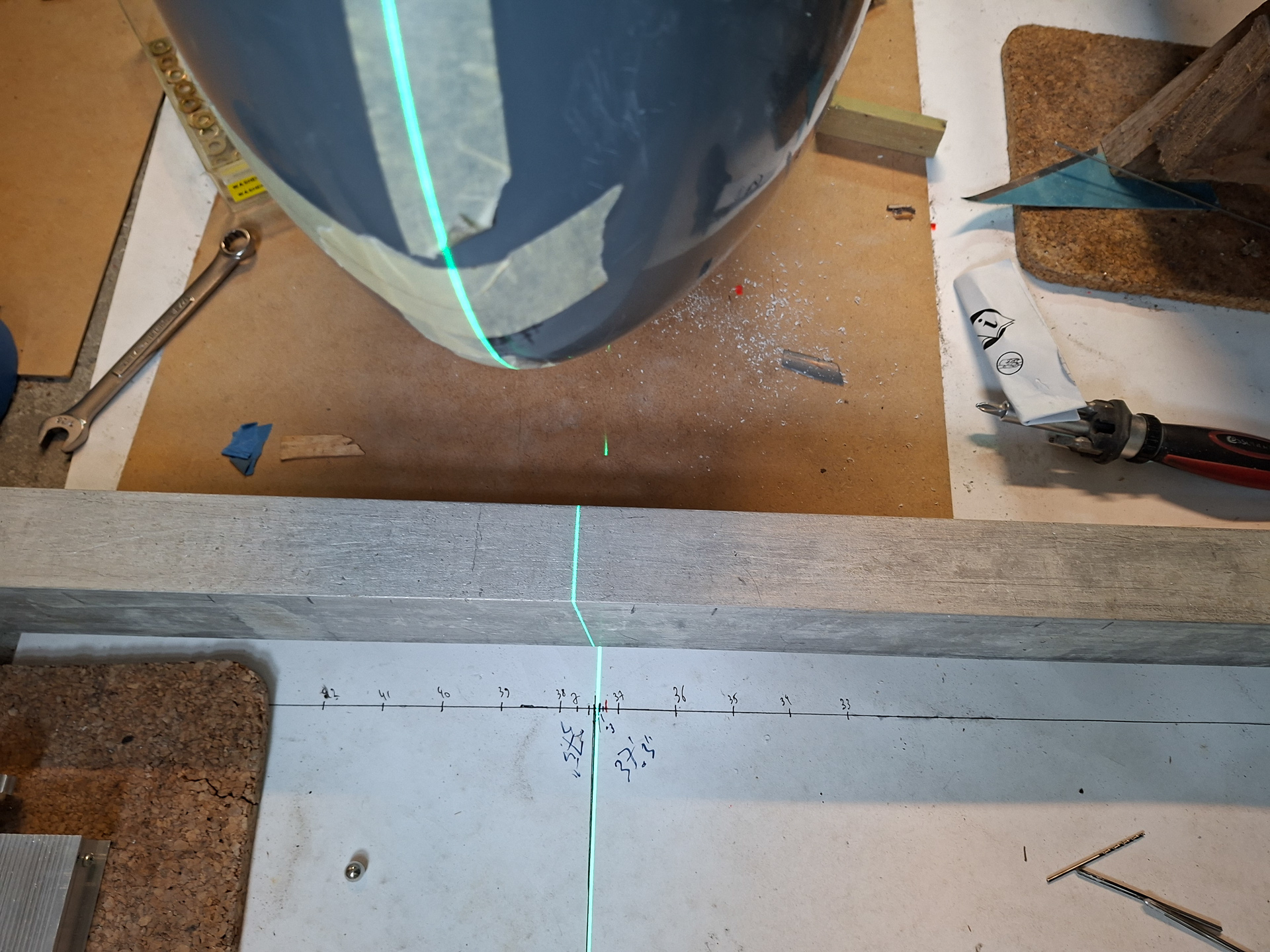
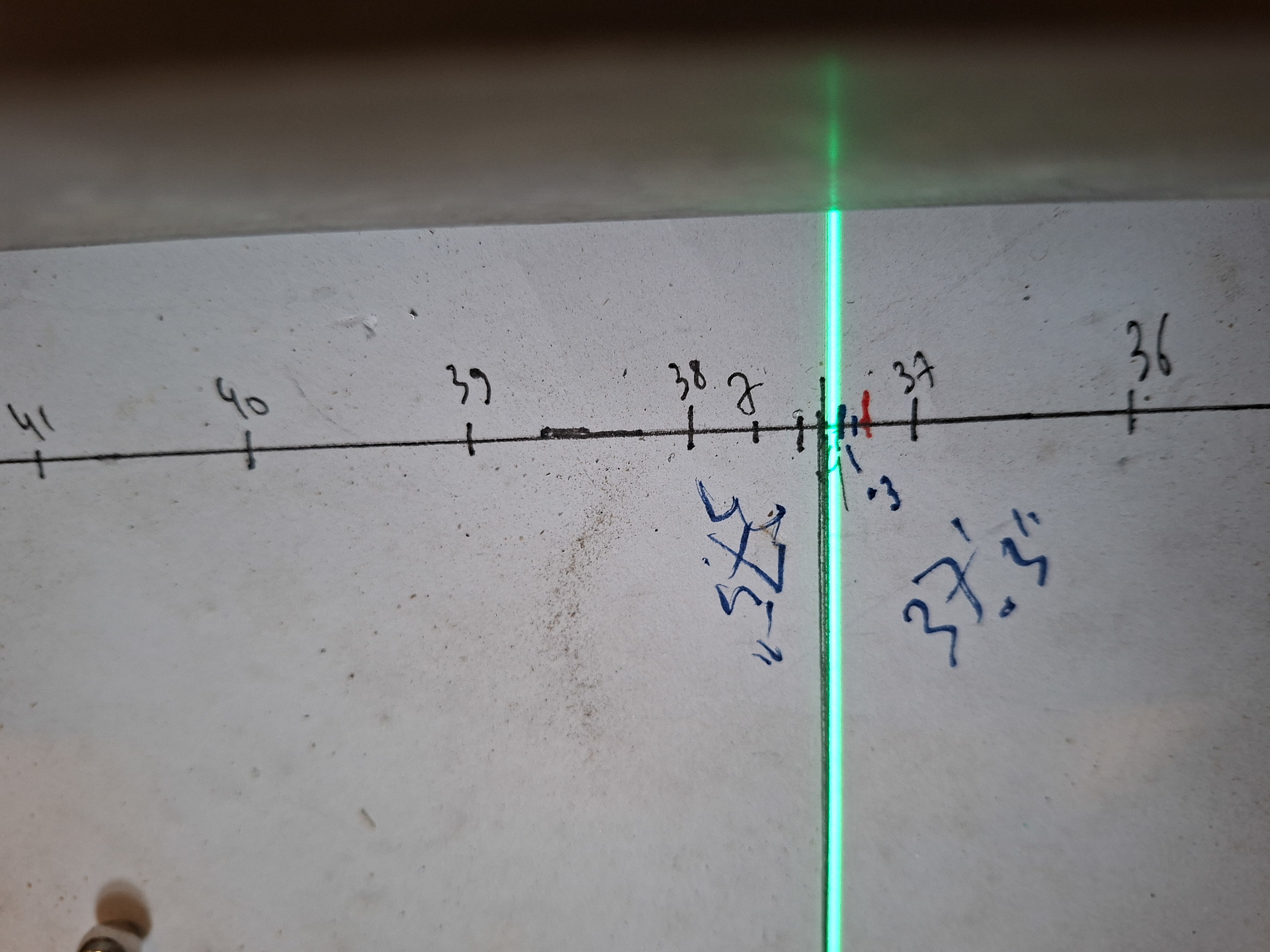
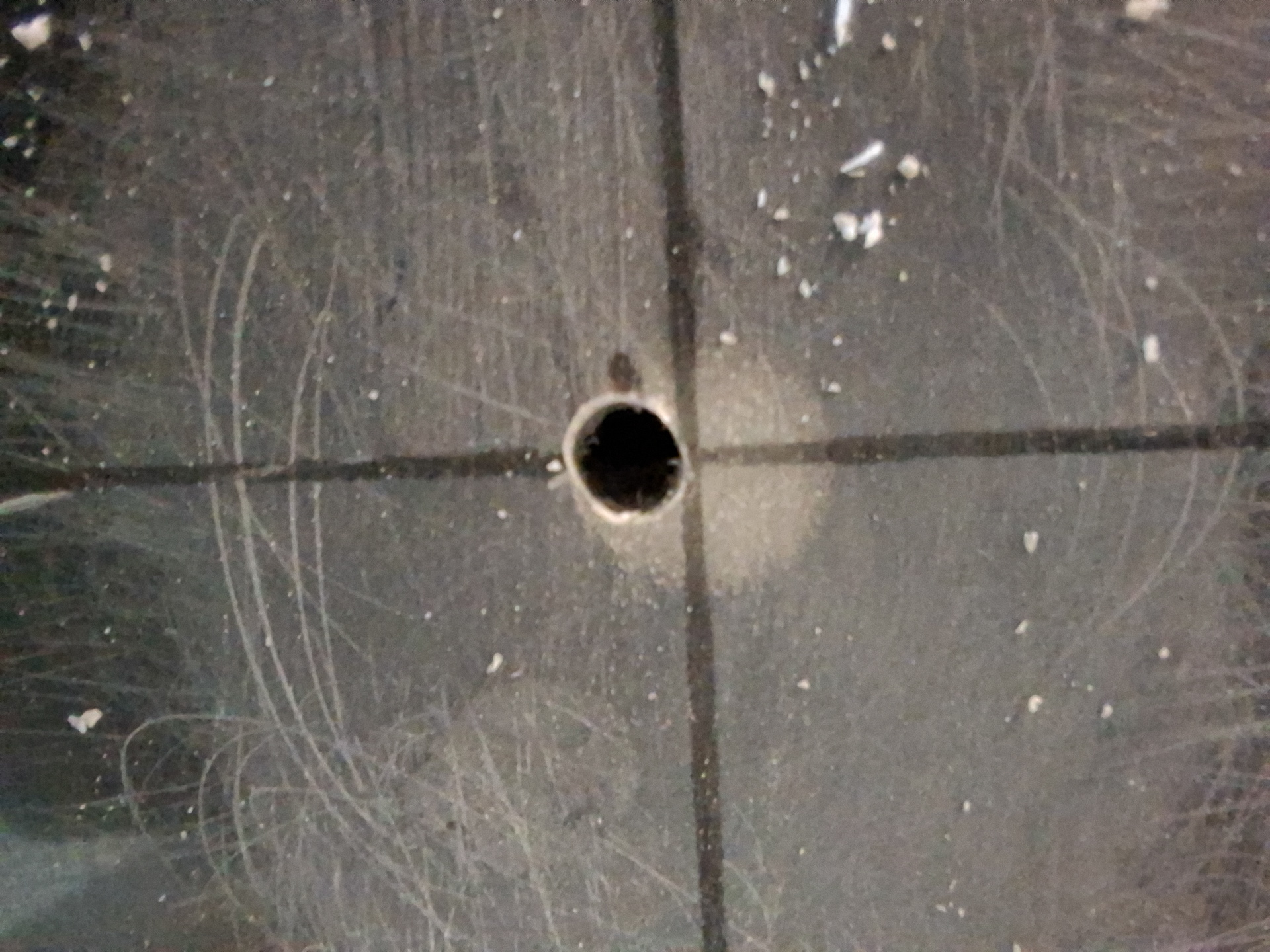
The laser projects it's line nicely on my wheel pant centerline and goes through the front and tail centerline
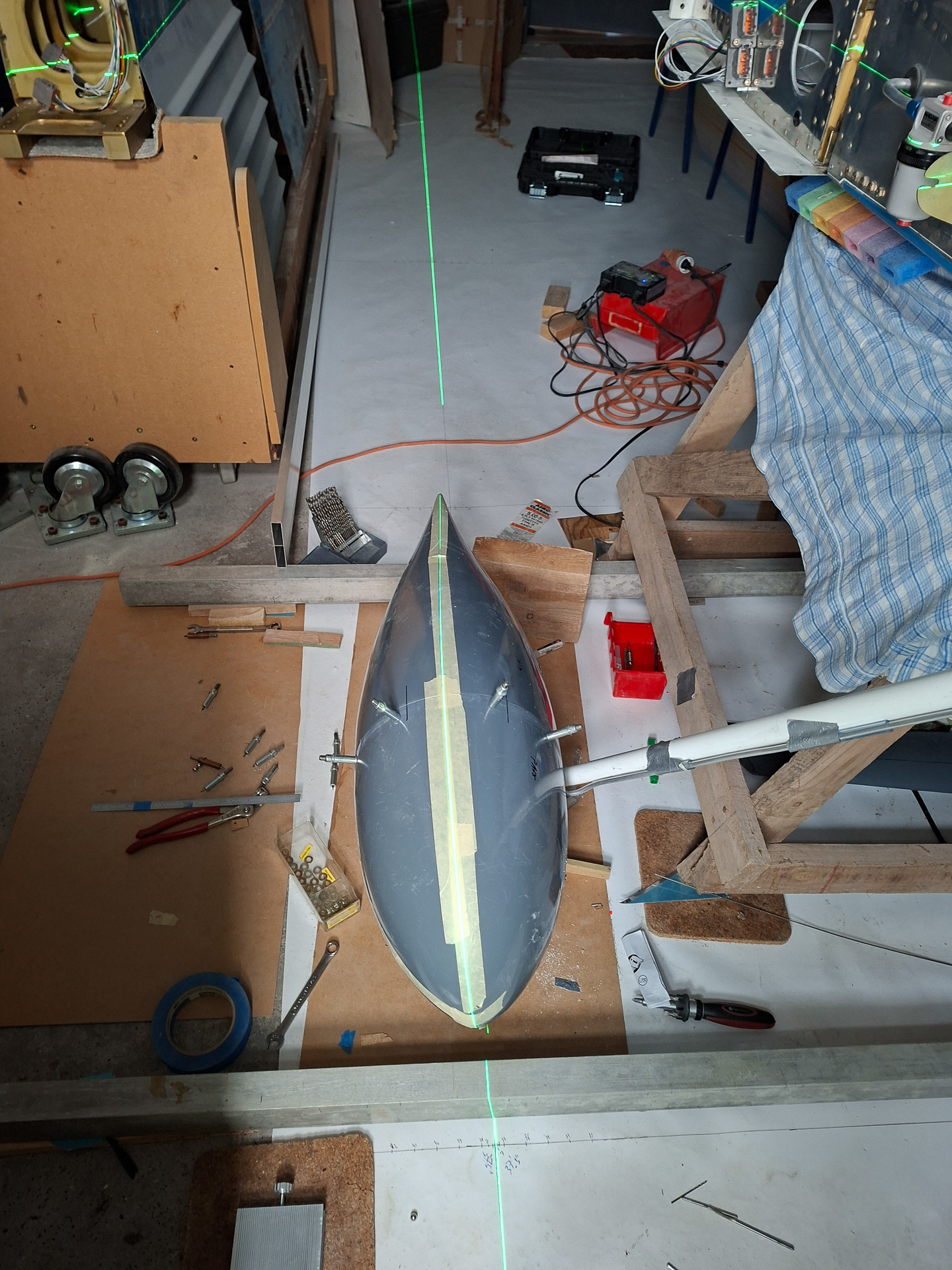
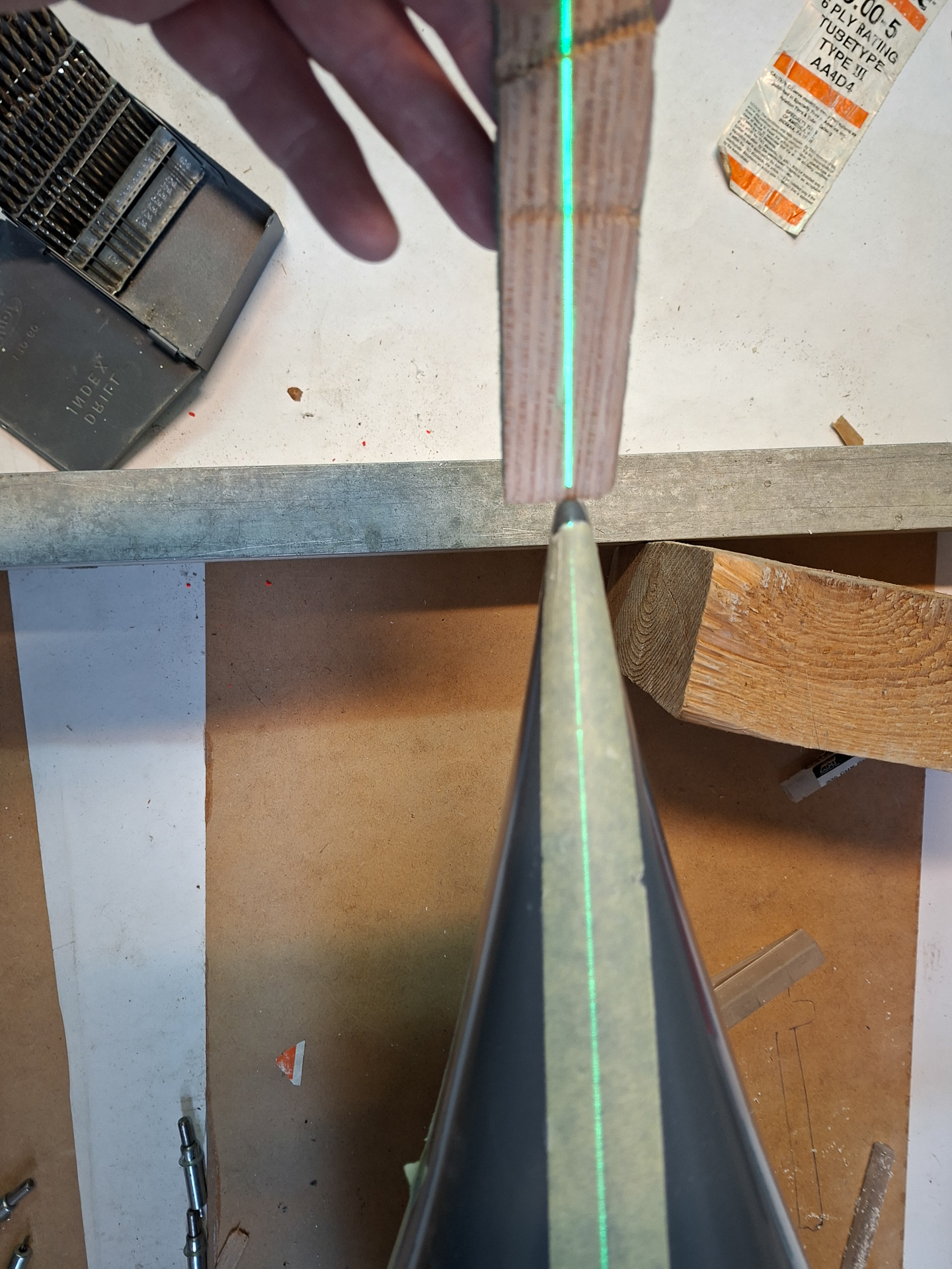
Close up shot
As I'm satisfied now with this, I can move on and define the main wheel fair angles on the gear legs. This is a critical job. Vans explicitly mentions it in the manual that 1/4" alignment error can cause half a skid ball deflection and requiring significant rudder input to overcome the induced yaw.
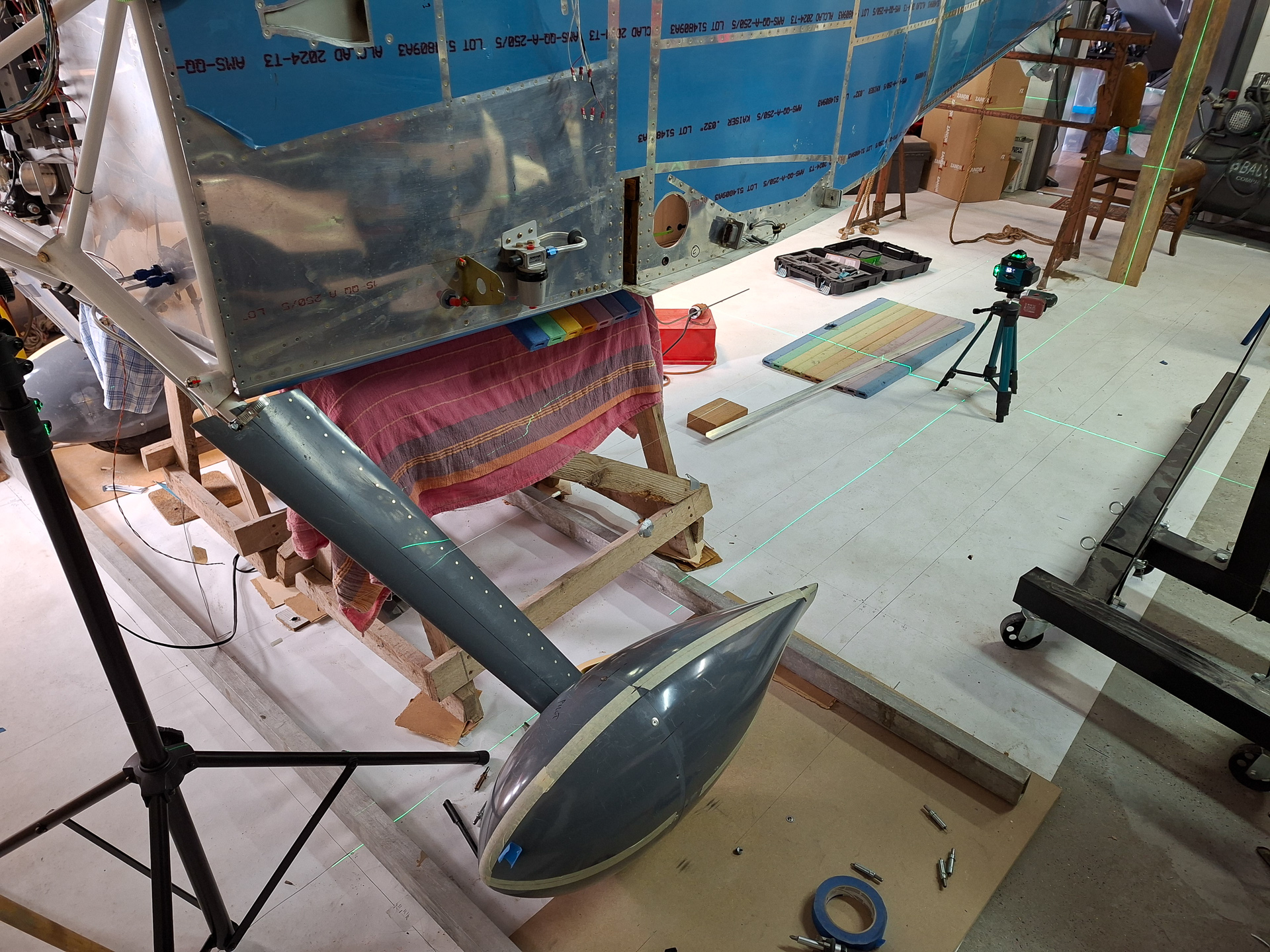
The way to align the wheel fairings is to use a fishwire and run it on both sides of the gear leg fairing. Place it at an equally choosen height and at the displaced centerline of the airplane.
A trick is to use some plastic tubing to allow the string to move closer together as you approach the gear fairing.
It started at the middle of the fairing. You should measure in at least 3 points : mid, top and low points to check for twist.
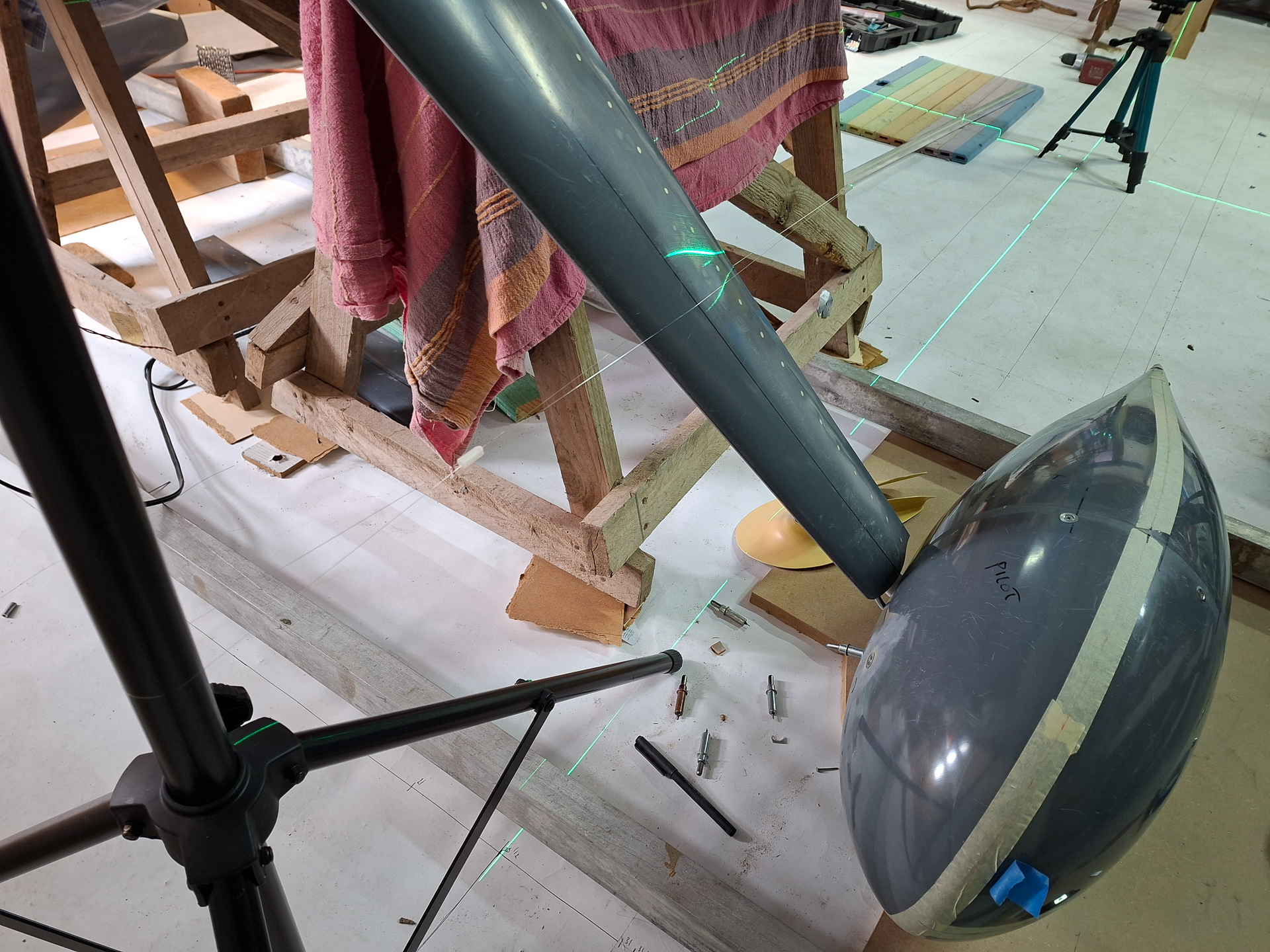
In this image, you can spot the fishwire setup and enclosing the fairing.
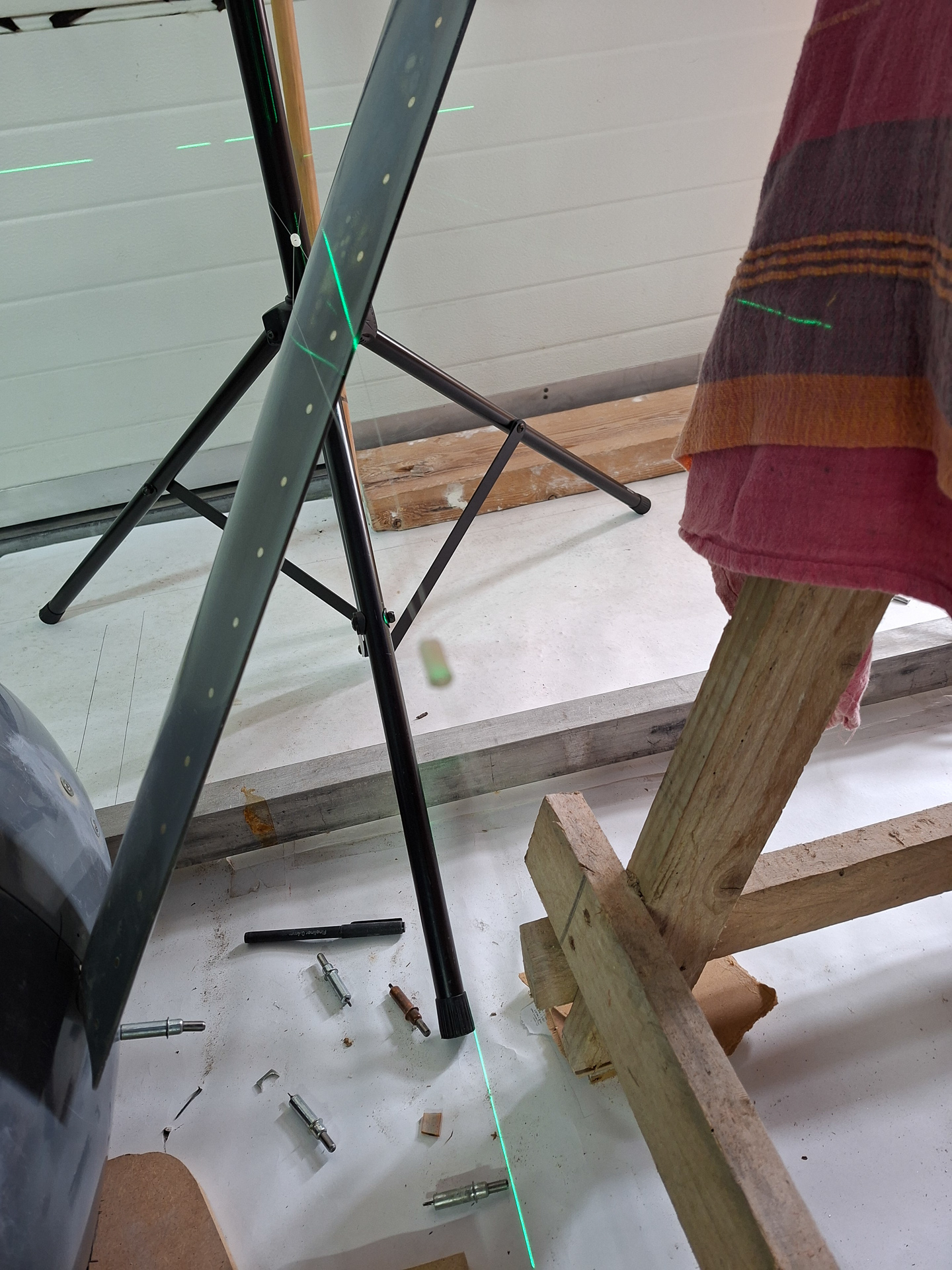
As indicated in the plans, the rear of the fairing but be nicely centered in between the strings.
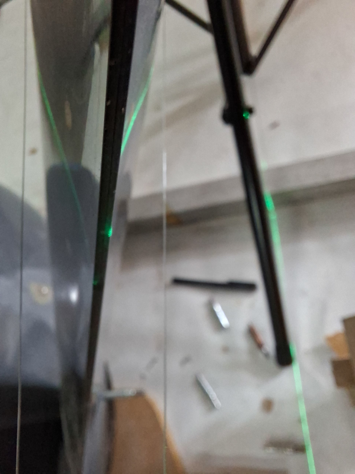
On the rear side, a wood block is put underneath the horizontal stabiliser. The vertical projection line of the laser indicates the horizontal location. The horizontal laser line defines the vertical location. I drilled a #40 hole through the wood and ran the fishwire through the hole. It's attached on the rear side.
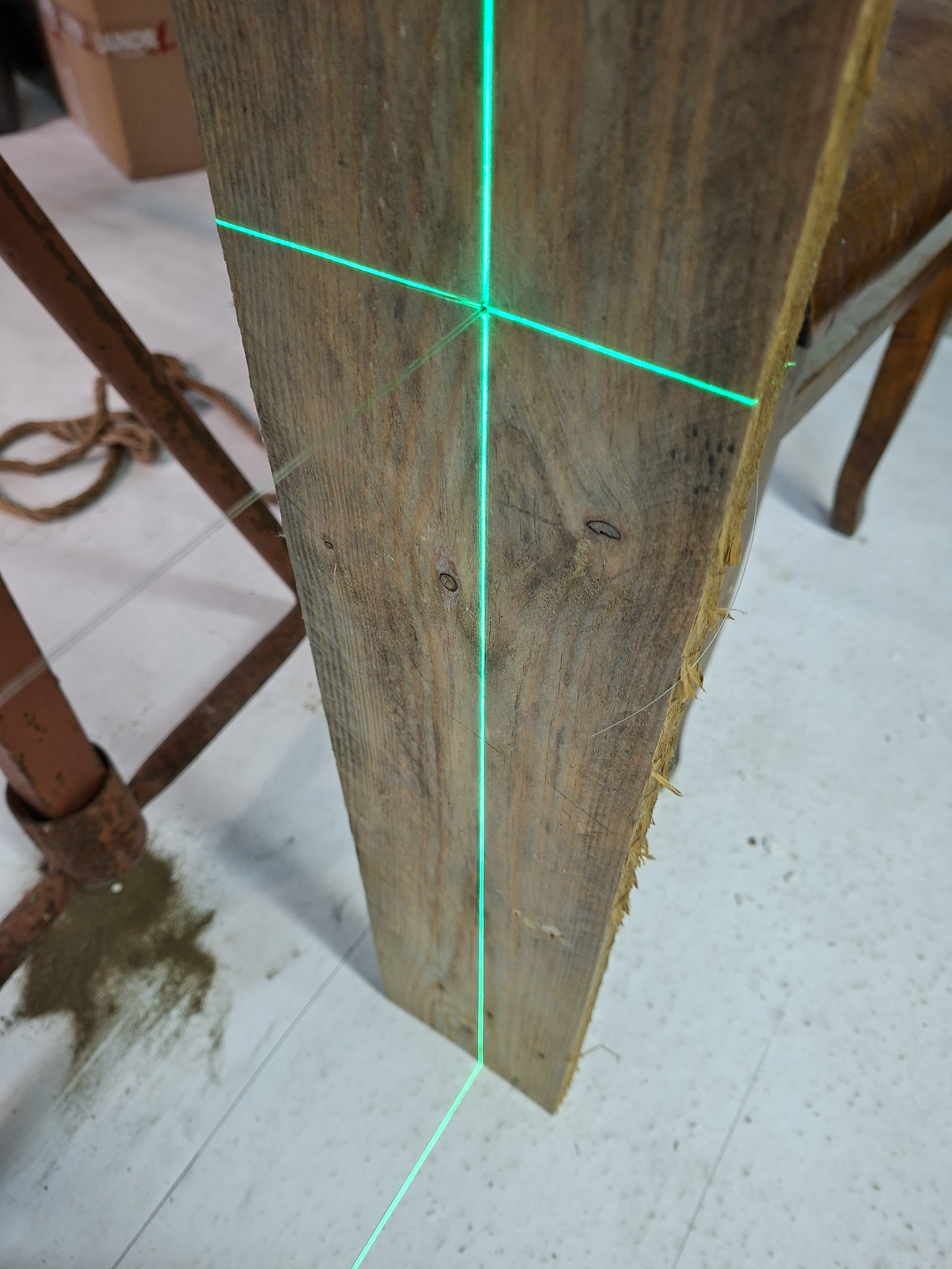
Also on the fairing, the horizontal line defines the vertical position (I used a bit of cardboard to hold it next to the fairing so that you can easily see the horizontal laser line.
In the front I use a tripod stand and align the wire also according the height and vertical centerline of the laser.
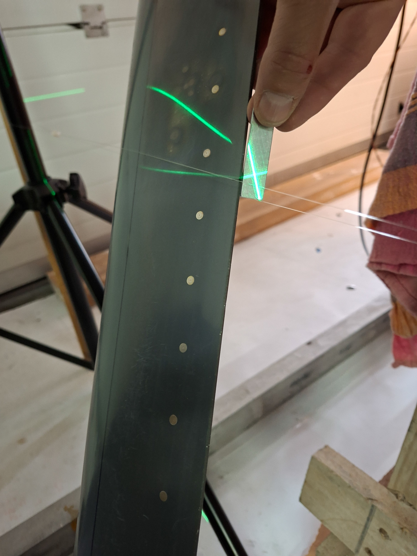
With all this in place, you can start playing with the orientation of the wheel fairing. I made this small cardboard template that has the green line representing the trailing edge of the wheel fair, and some equal distance blue and black line to check the position of the wires. Ideally, the green line is aligned with the fairing trailing edge and the two blue lines cross exactly over the blue lines. As you can see in the image below, I have good alignment here. I moved the plastic slider towards the fairing so that the wires move closer to the trailing edge and reverified at the black lines and also visually verified the distance. If not aligned well, at some point when you get closer with the wires, the wire will rest on the fairing while you still have a gap on the other side. This is not good. Even with small distance, you should maintain the same distance left and right without touching.
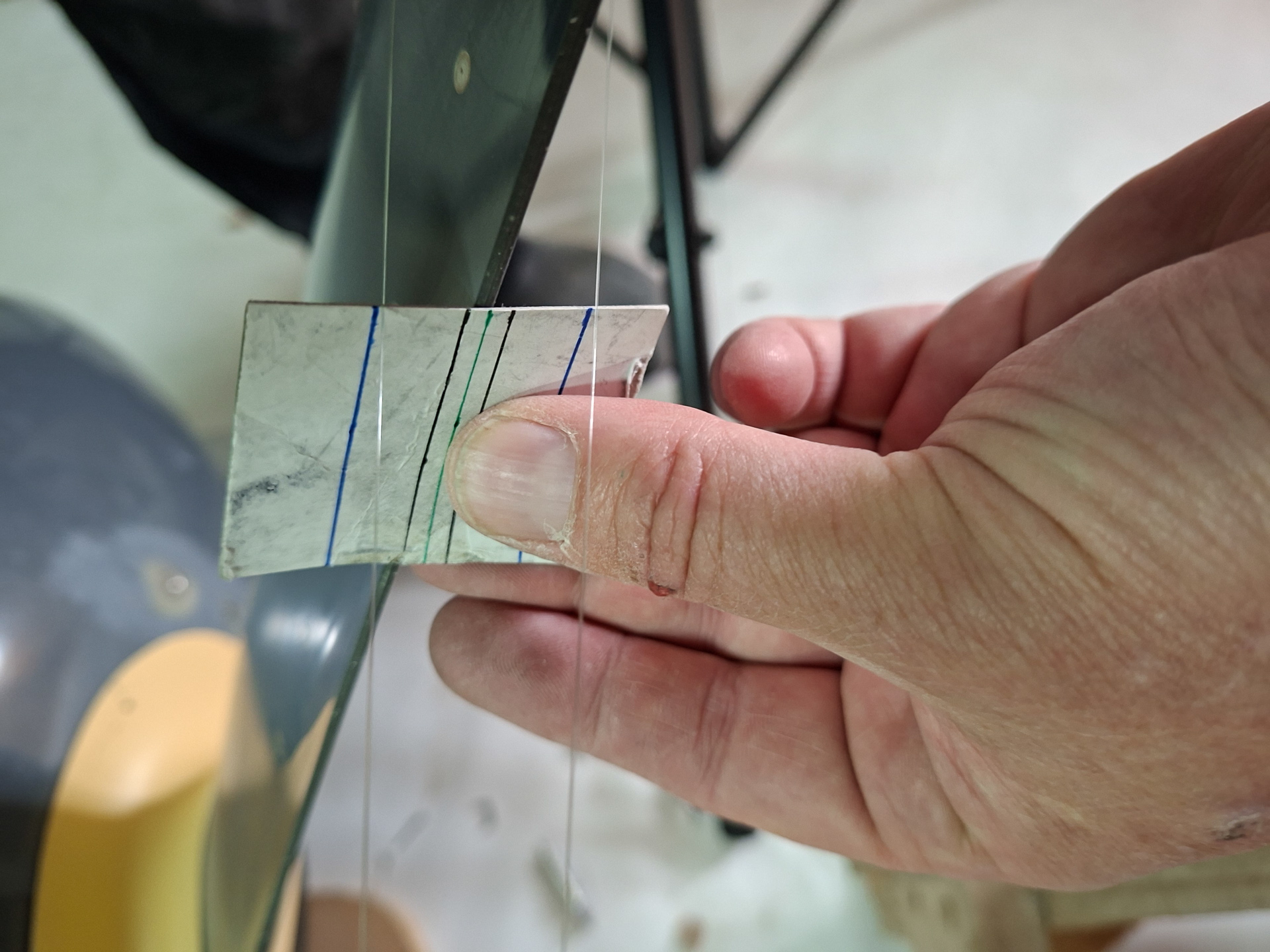
Made small adjustments and tried many times
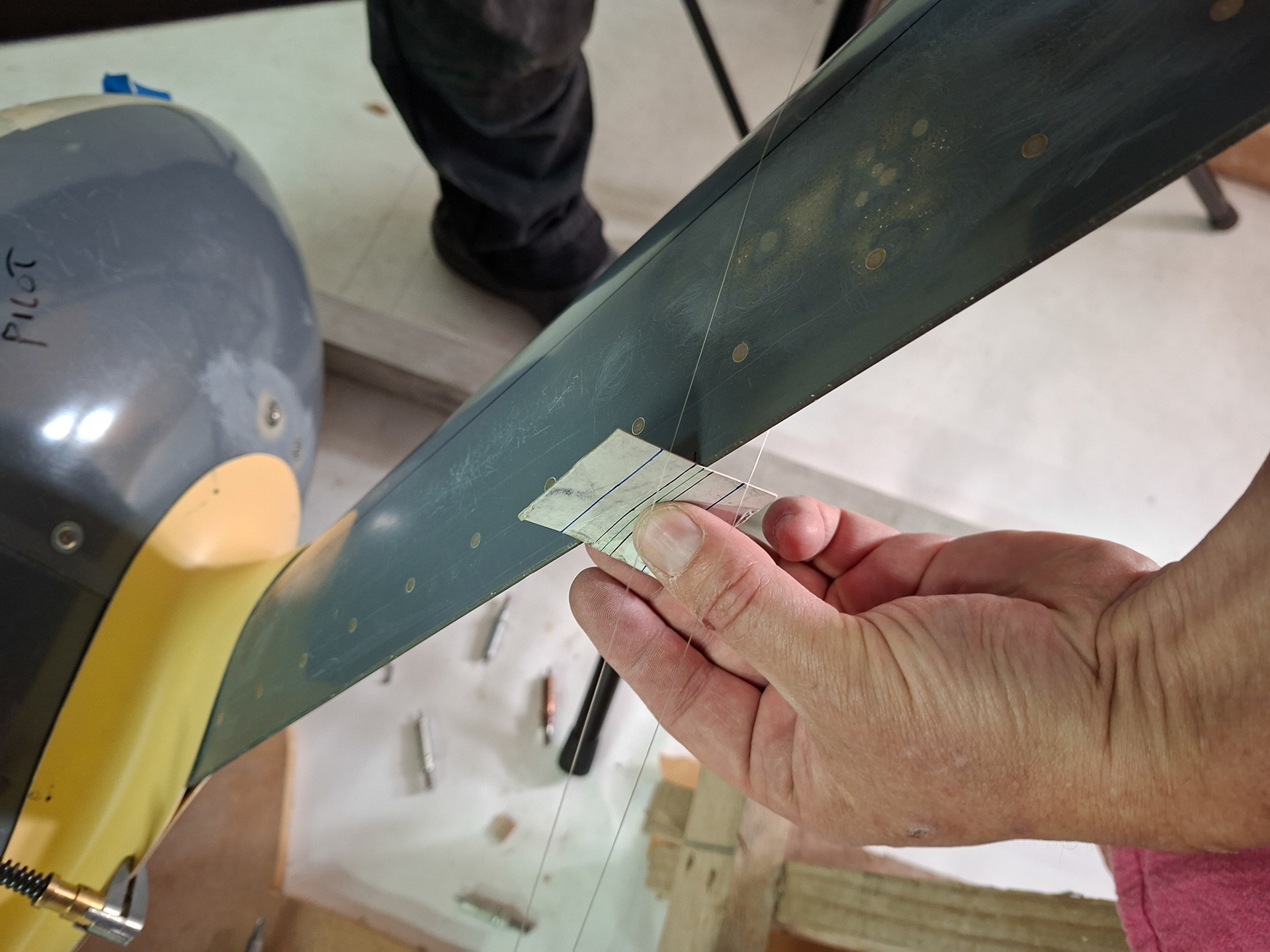
Then moved the wire up towards the top of the leg and did the same exercise. Below you can see the position of the wire on the upside of the leg.
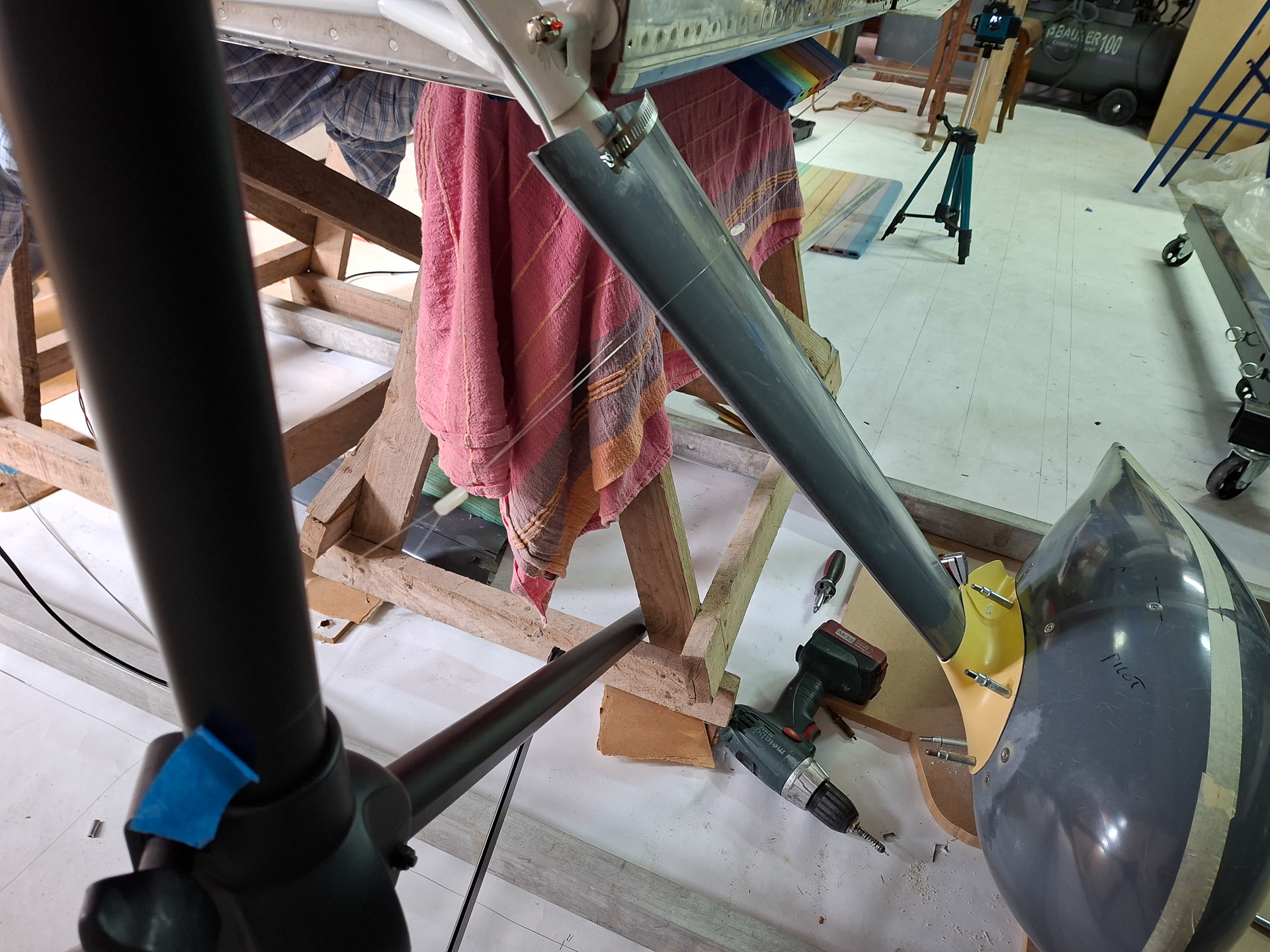
Here also the alignment remains good which means no twist in the trailing edge.
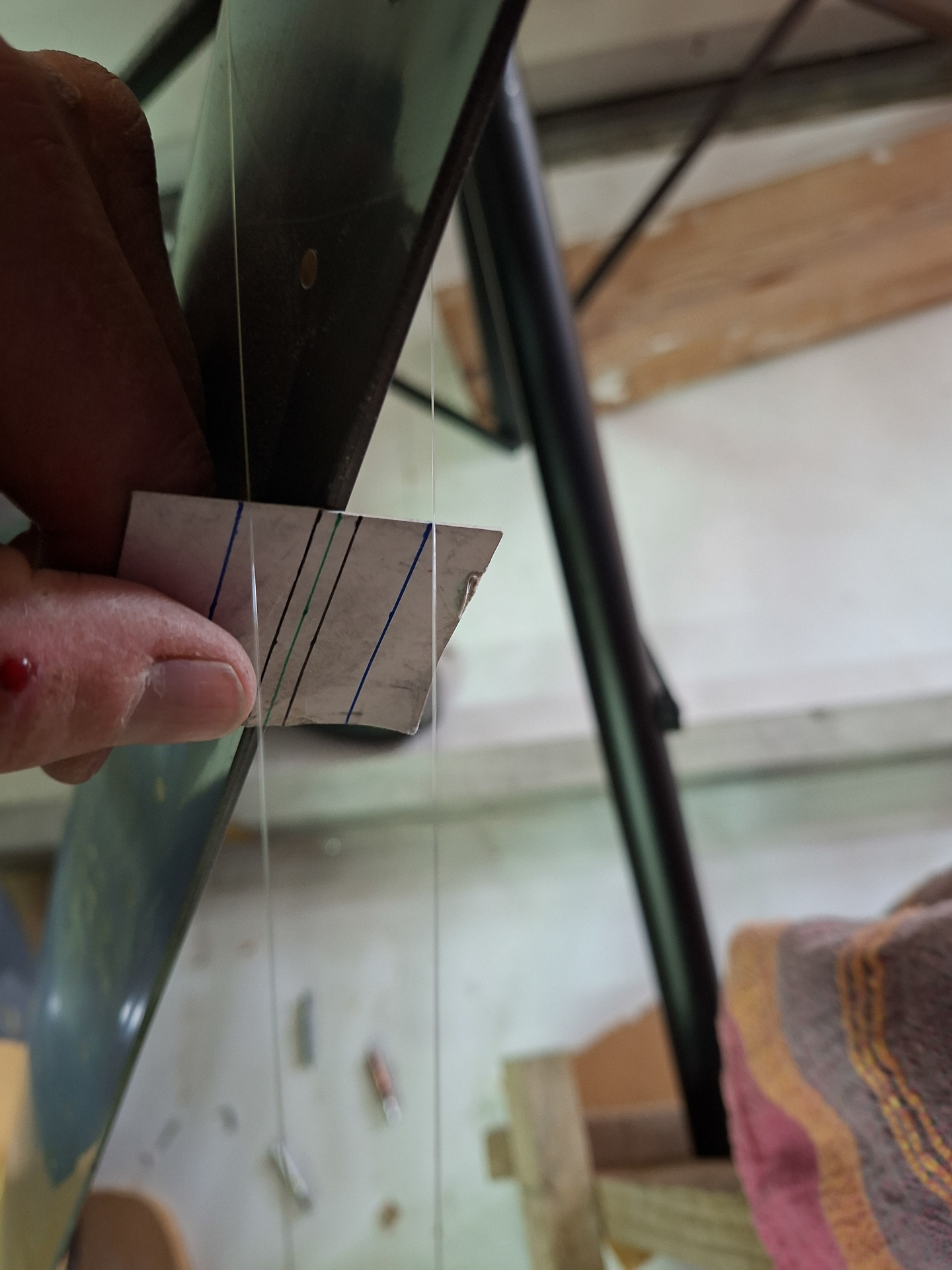
This is the little plastic spacer I'm using to move the wires inwards. As you see in the image below, even very close to the fairing, the alignment remains intact.
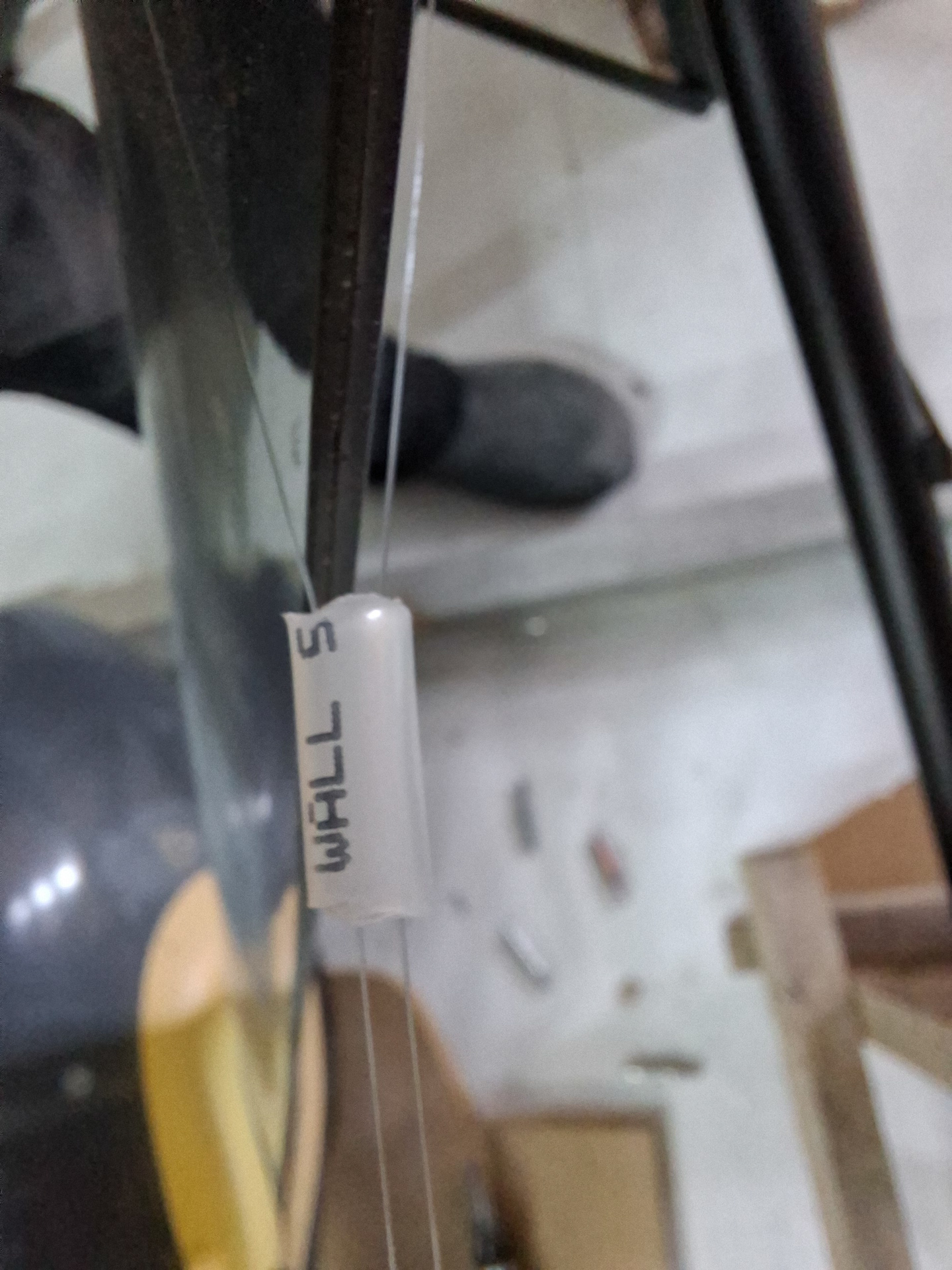
Then moved the string down, just above the position where the intersection fairing would be positioned.
Same reading, no twist. Nice equal distribution of space between the wire lines.
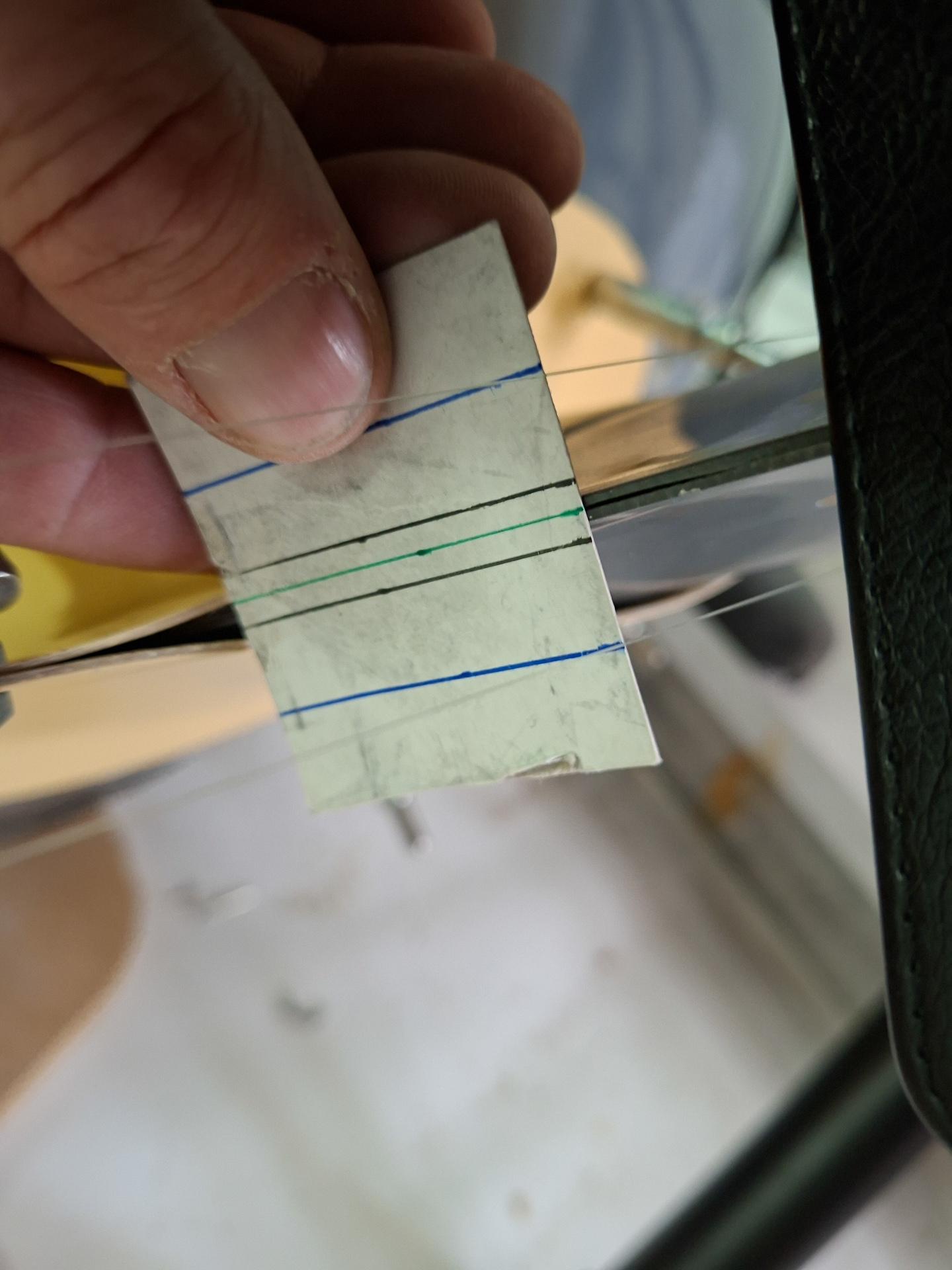
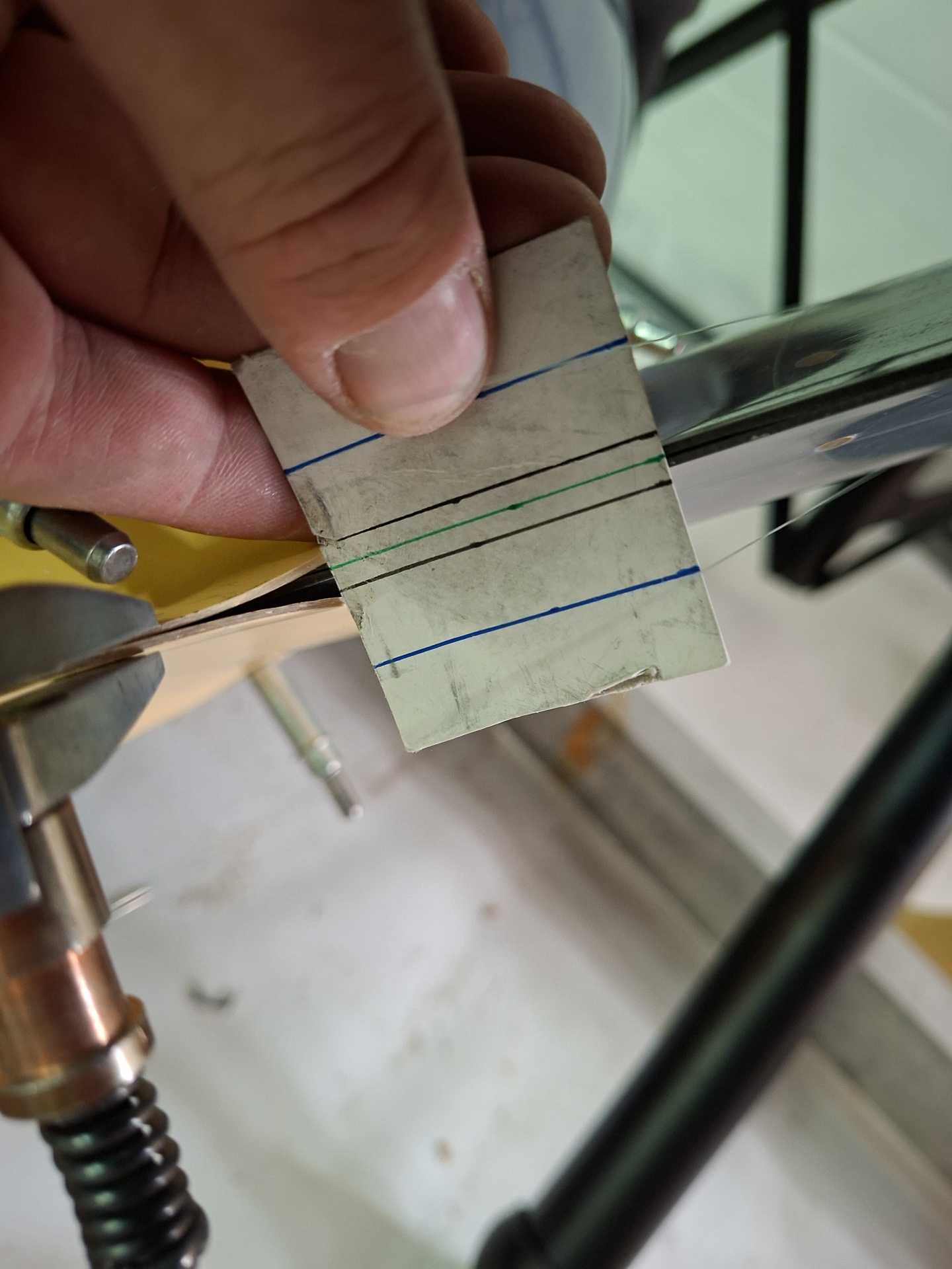
Moving closer with the spacer tube. The space is pretty equal, it's difficult to take a picture that shows this in macro mode.
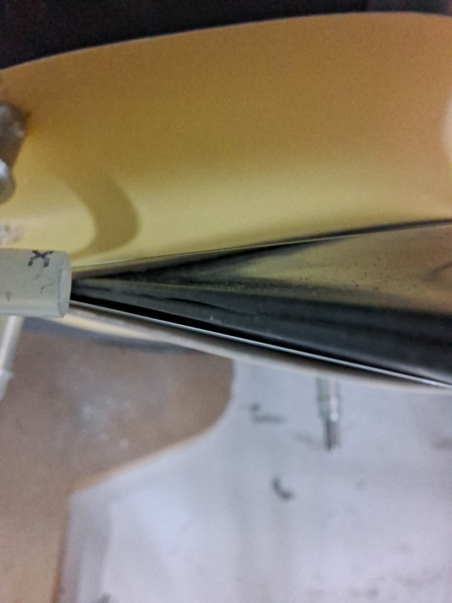
I was pleased with the alignment and defined some positions on the intersection fairing where I would be drilling attachment holes.
There are no instructions on these positions. It will be #6 screw held in a nutplate. You have to preplan carefully so that the drilled holes don't interfere with the brackets underneath.
The intersection fairings come from rvbits.com. I am really pleased with the quality of these. It would be a nightmare having to do this by yourself with modelling clay.
The edge distance I used was 3/8" for the #6 screws. 3 locations in the front and 2 in the back. The front alignment came out quite good.
To make the epoxy fit little better, you can heat it with a heat gun and redefine the shape. This has it's limits but small corrections are ok.
I plan to wrap the leg and pant in packing tape and will probably apply some epoxy underneatch so that there is a perfect fit all around.
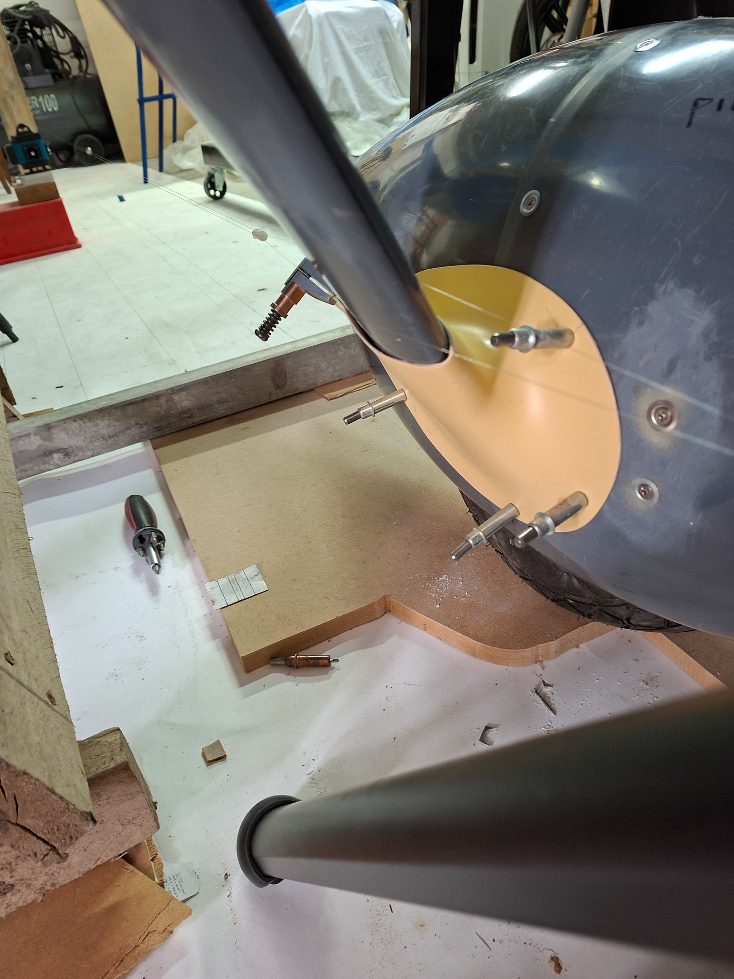
In the rear, the top flange is very close to the attachment screw of the gear pant but I think I can still use a tinnerman washer there.
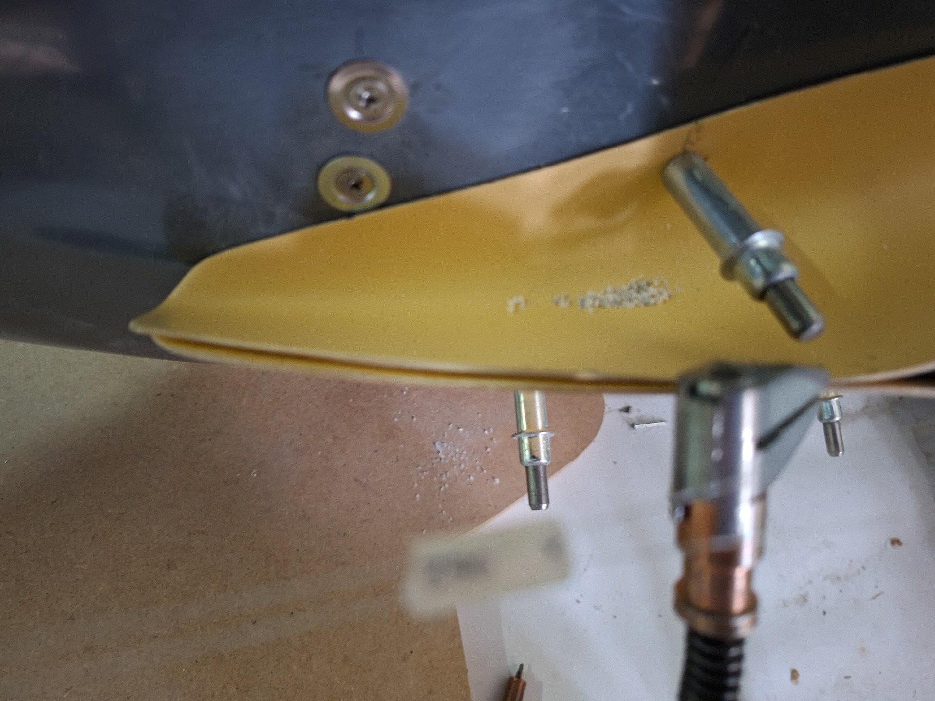
In the rear, I had to pull the lower part up a bit and have it align with the top flange. The excess will be filed and sanded of.
I also temporarily attached the top intersection fairing. This will look really good once painted and final installed.
The bad part of the story is that I can't attach this one yet as it needs the cowling in place for fitting. Made some markings on the leg and fairing to be able to repositions later.
I hope that the alignment and orientation is set and defined with the bottom intertersection fairing along as I don't feel like doing this once more when the engine is on.
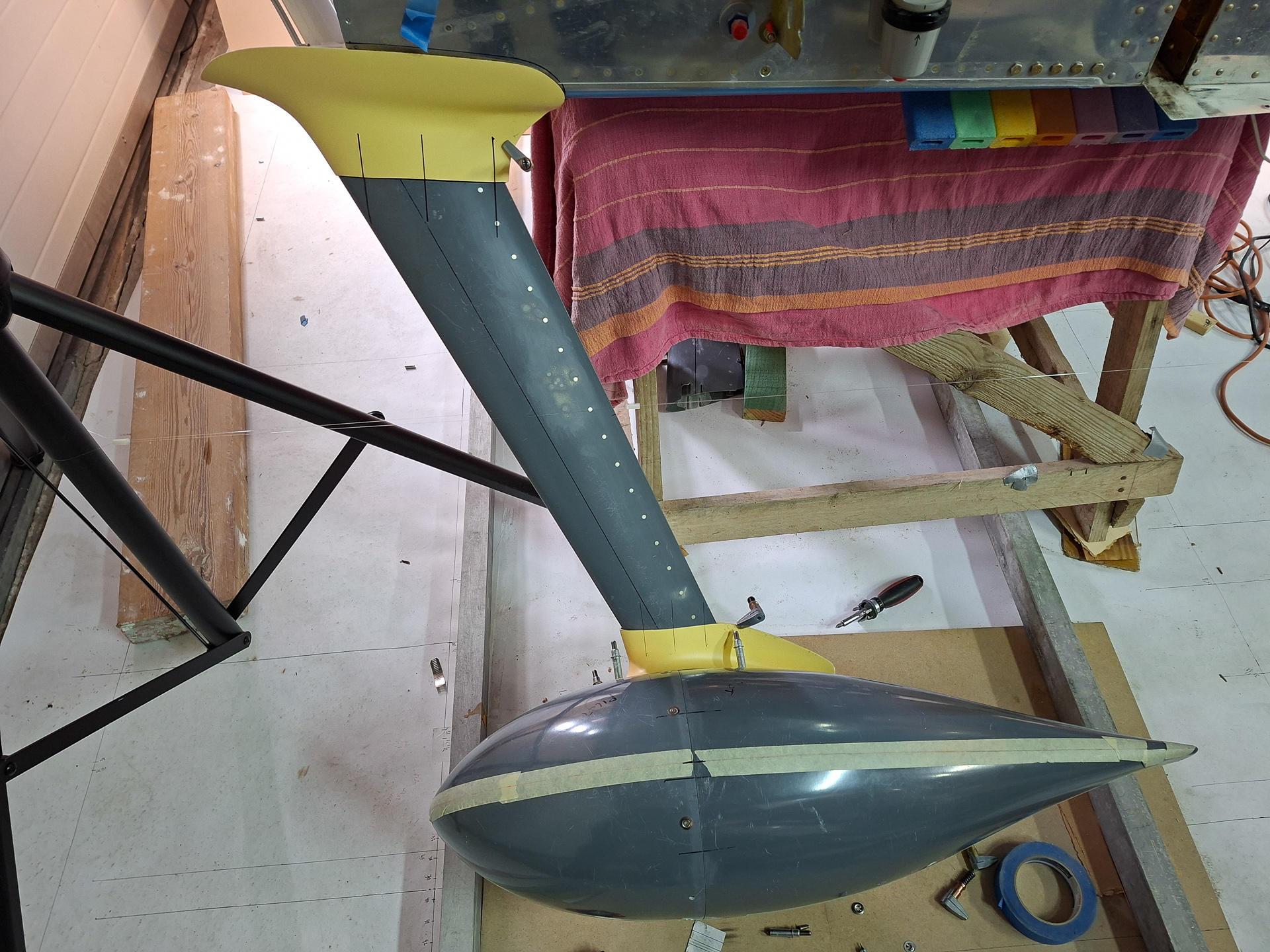
Here you see my alignment stripes. The rear pant has a little step inward. I will probably fill this up with epoxy filler to eliminate the gap.
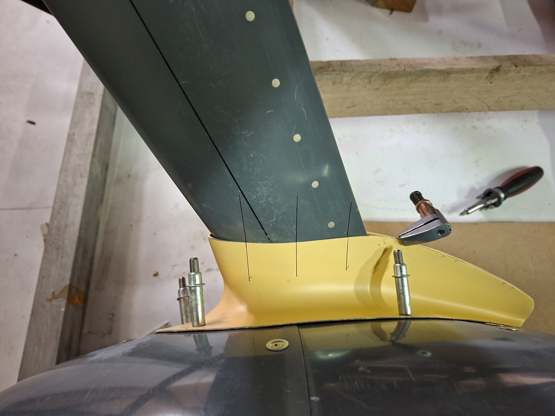
The top fits well and I think this will be able to go on without a lot of tweeking.