
Another day of measuring and chickening out not daring to drill the first holes until I'm absolutely sure all is ok.
As in the start of every session, I check if the centerline of the airplane is still aligned with my reference line on the ground.
Sometimes you bump into the jacked up airplane and small movements are made causing changes in center line track.
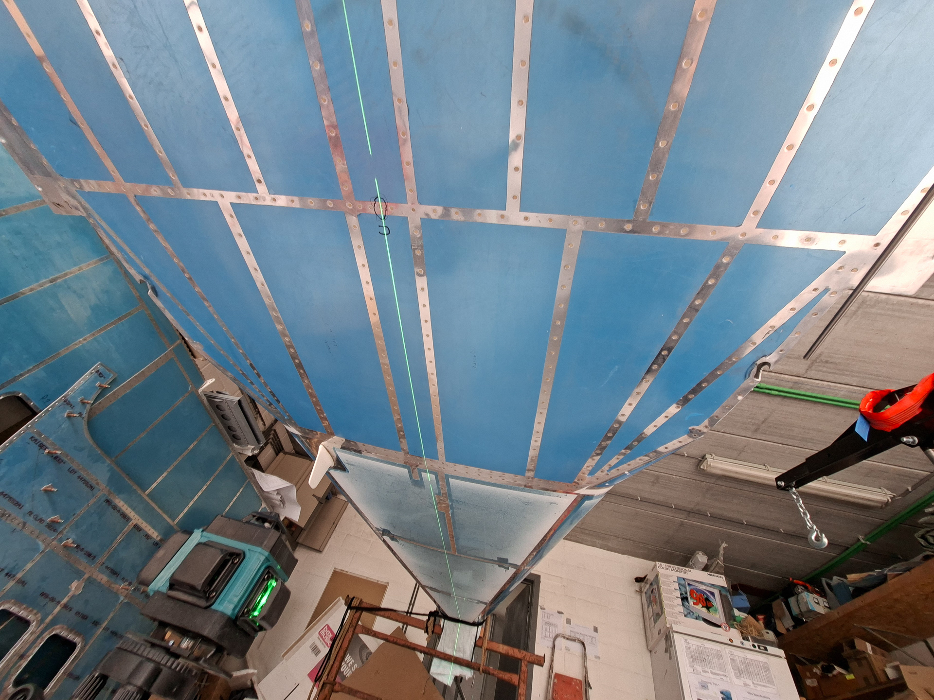
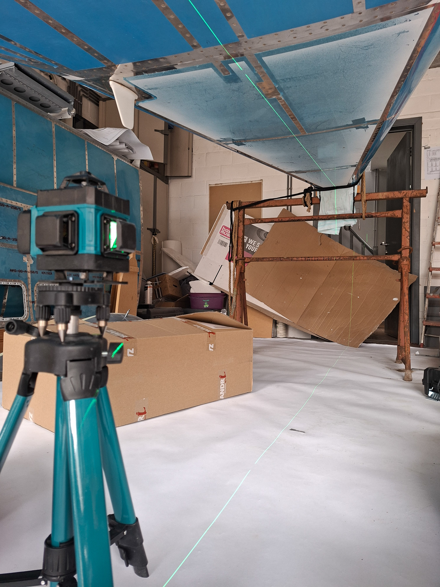
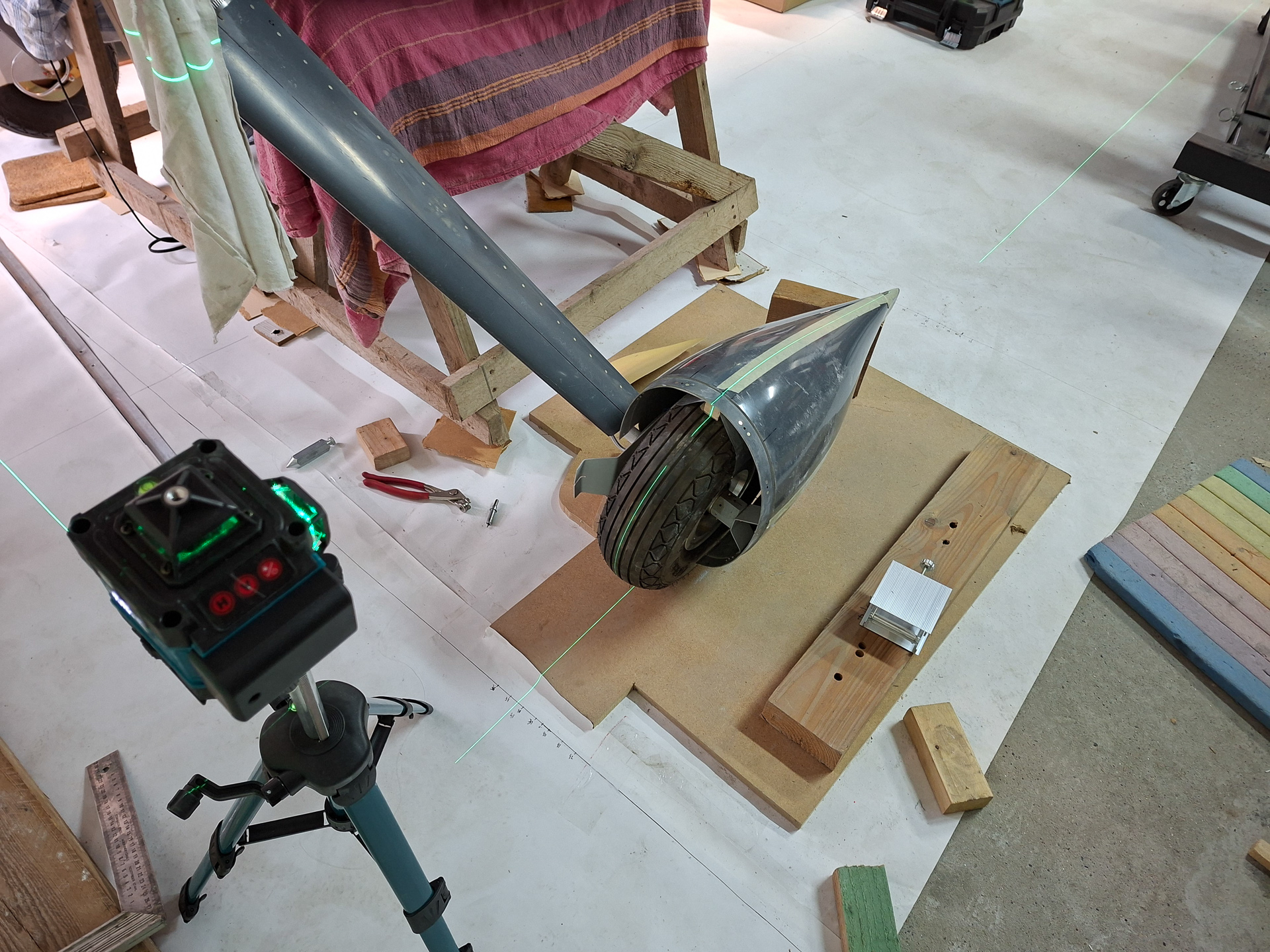
I use a digital laser level that projects a vertical line on the ground and at the same time on the bottom of the airplane.
I align it perfectly with the line on the ground and then make sure some reference rivets on the belly are in the middle of the laser line.
In the image belown near the tail, my reference is the middle between two rivets. And more forward, I made a circle on my reference rivet at the baggage bulkhead bottom.
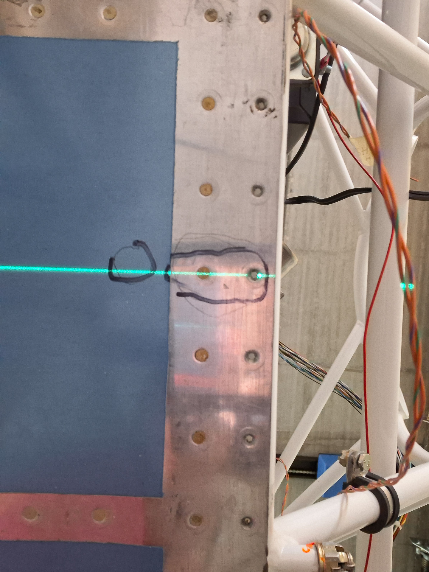
In the front at the firewall, there is a center hole rivet in the middle. The line also runs through this rivet hole.
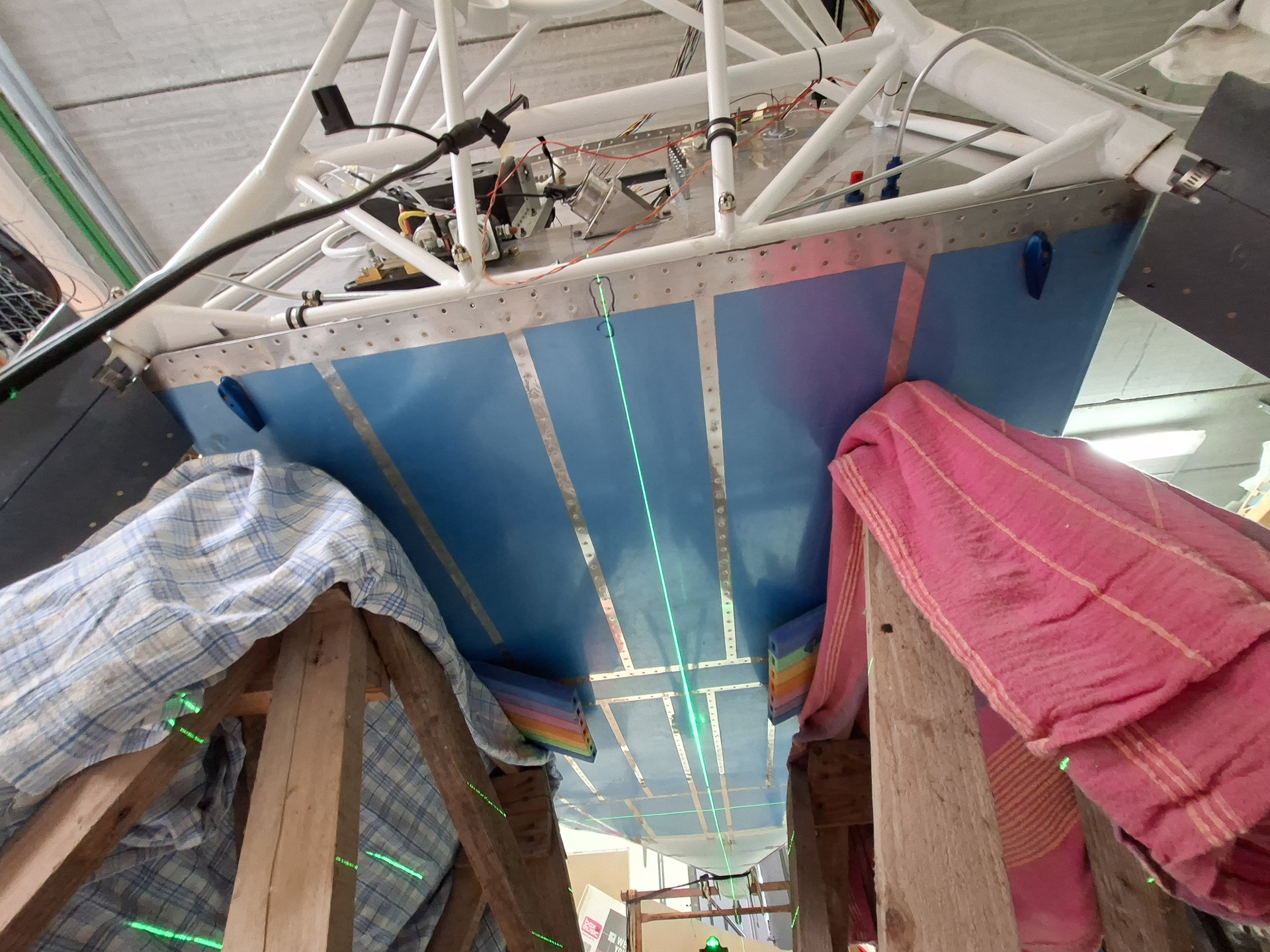
Now I'm sure the plane is perfectly in line with the ground reference line which you see here on the paper without the laser active.
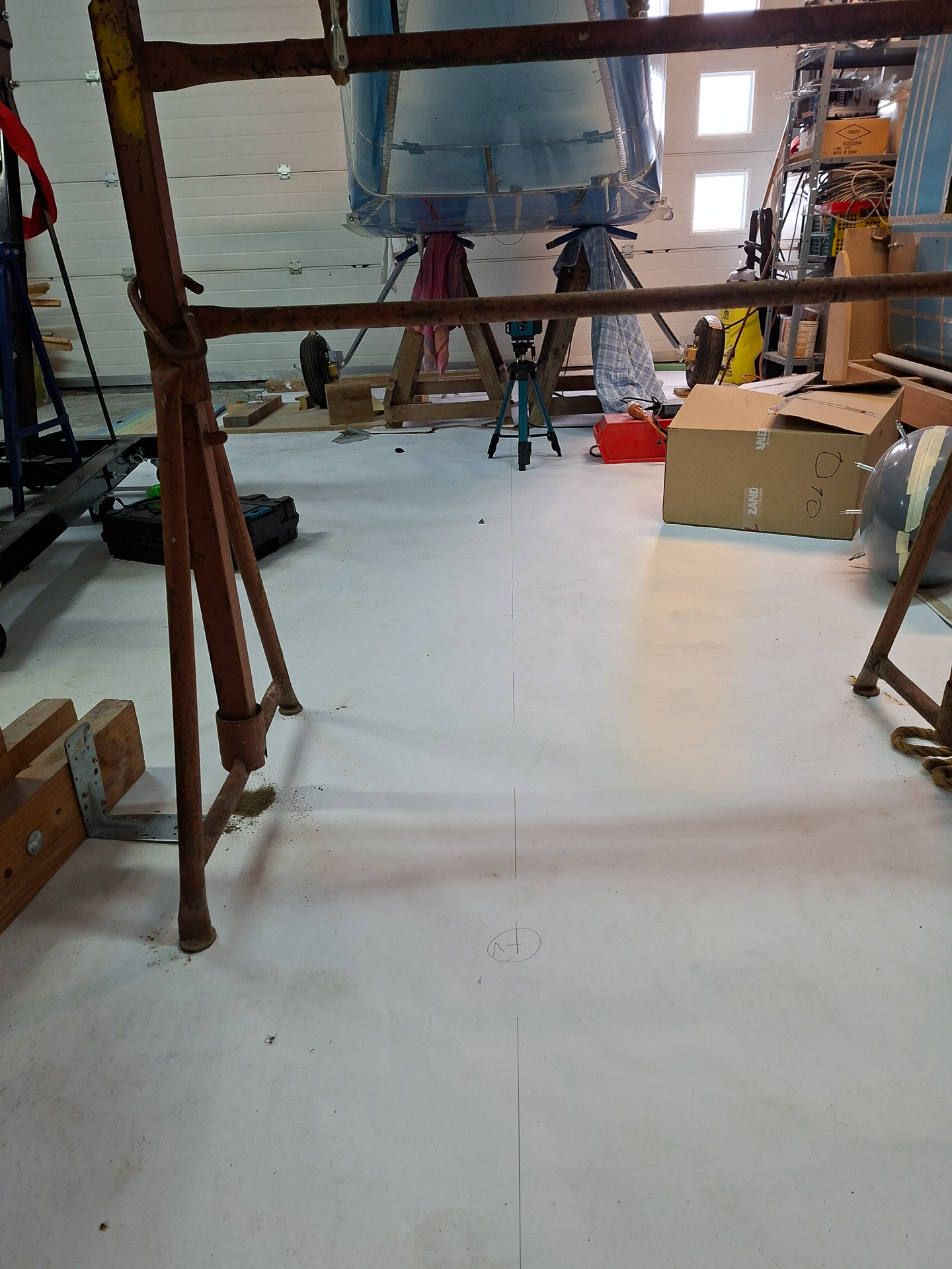
All my reference lines a perpendicular offset of this centerline at various distances.
It's best to mark some offsets as you will need to find the correct distance when the laser is tilted to sit over the center of the tyre.
The idea is off course to have the laser line going through all the same offset points and then have the wheel pant perfectly straight inline with that line.
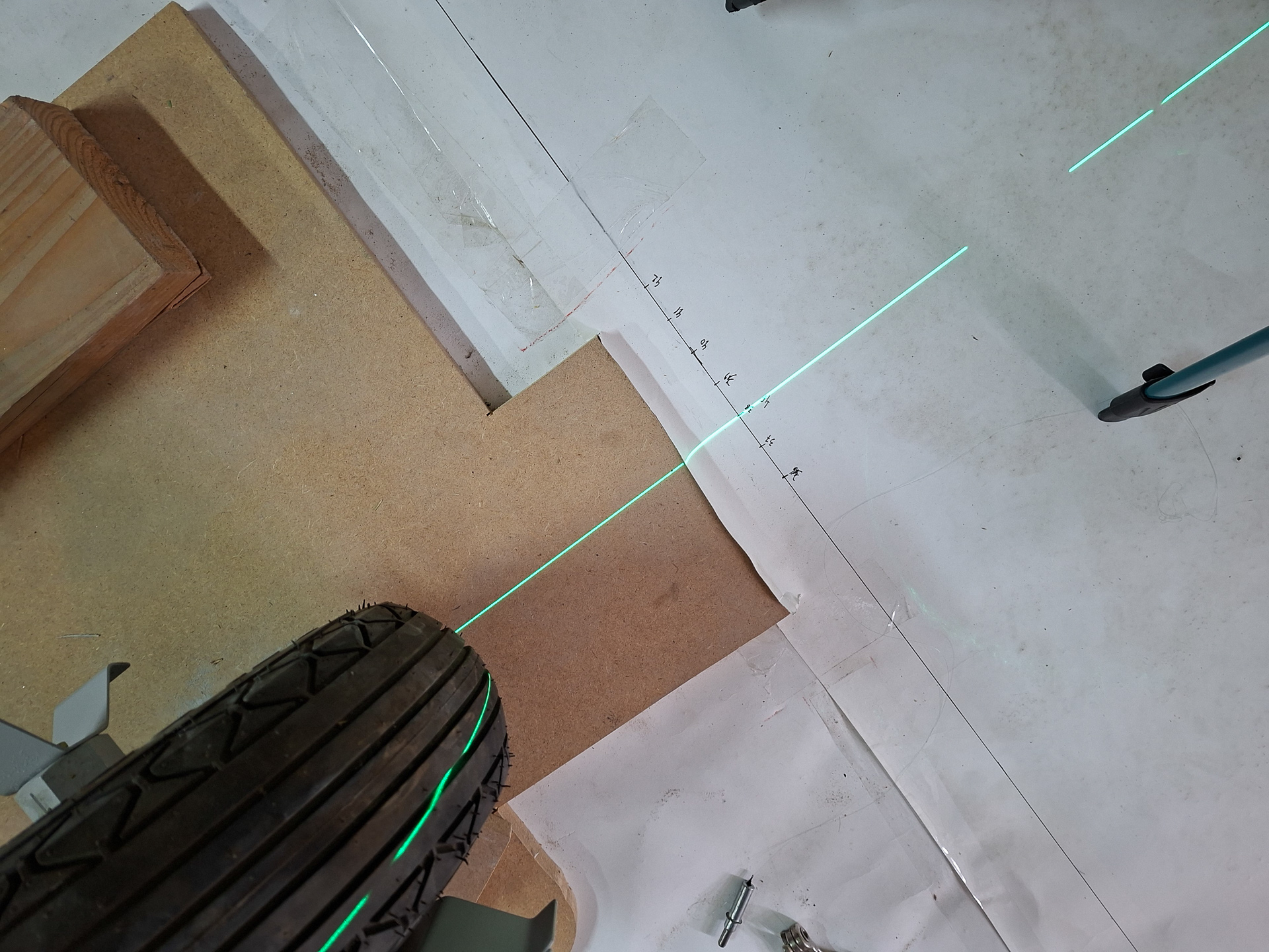
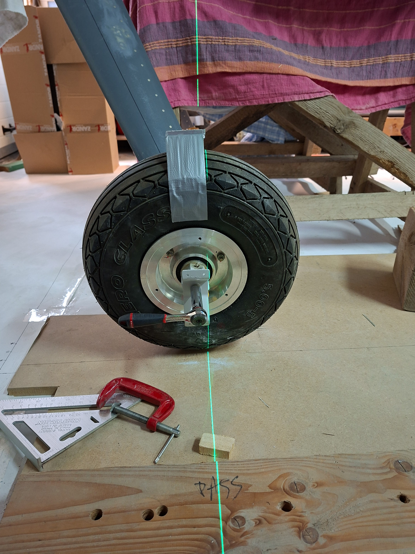
This is with the level standing straight. as you can see , that doesn't really help with the alignment of the tyre but it gives an idea of the offseted centerline.
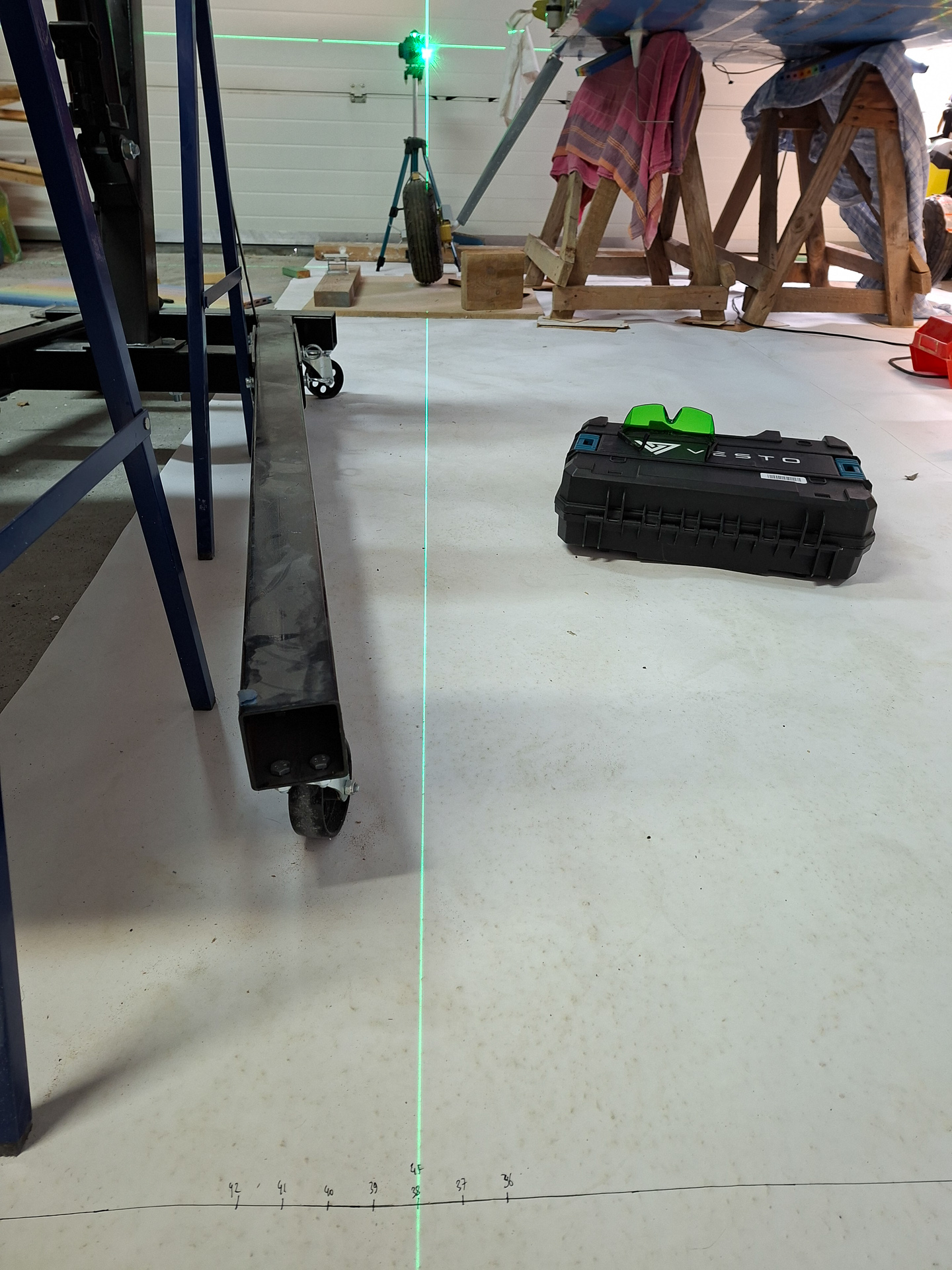
Then I tilted the laser to have the same tilt as the tyre and made sure the line is still a parallel offset from the centerline.
With this line defined, you can place shims between the gear leg cutout and the wheel fairing so until the line is perfectly parallel with the centerlin.
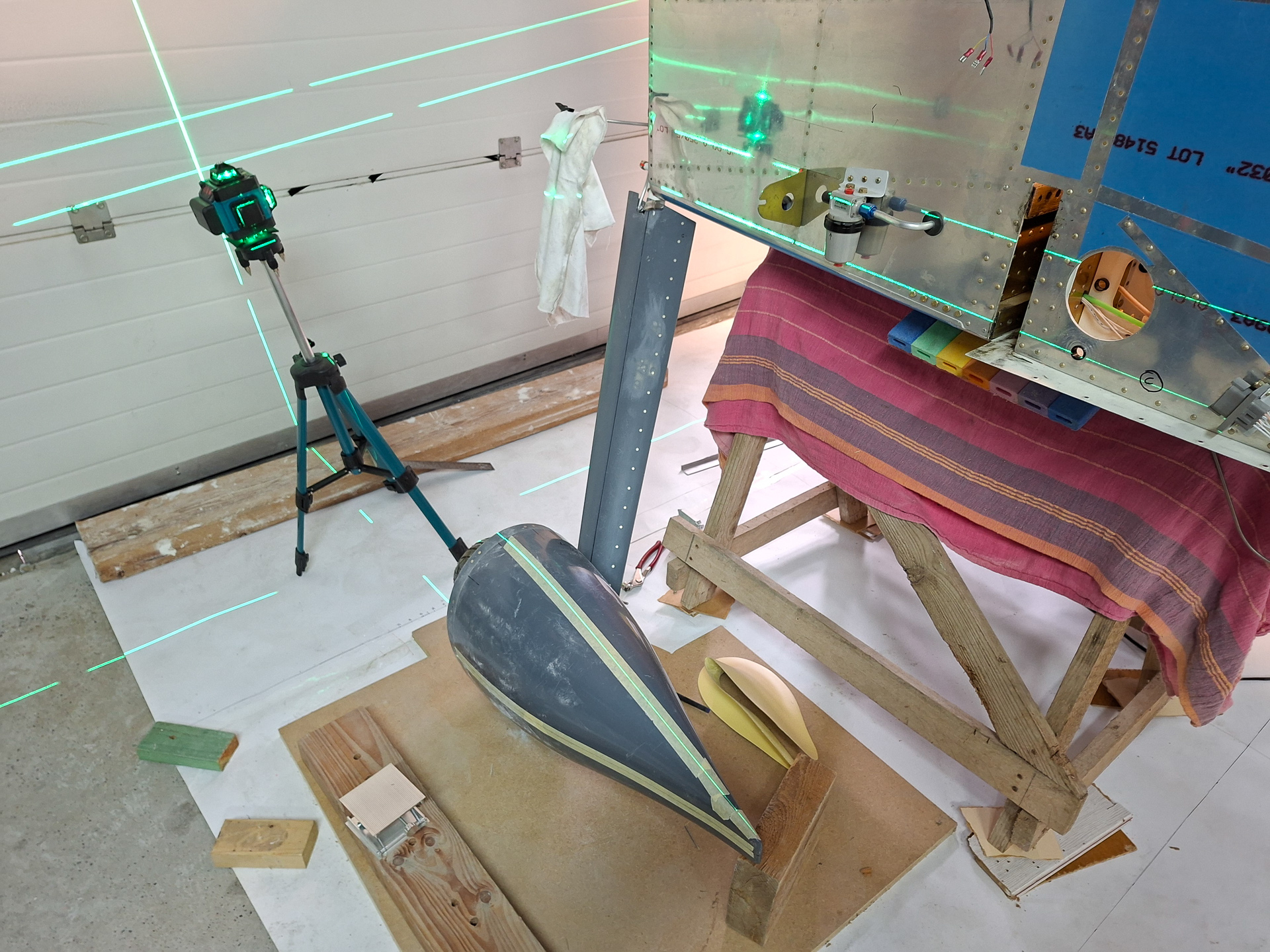
Here's another shot from the front to illustrate the tilt on the tyre
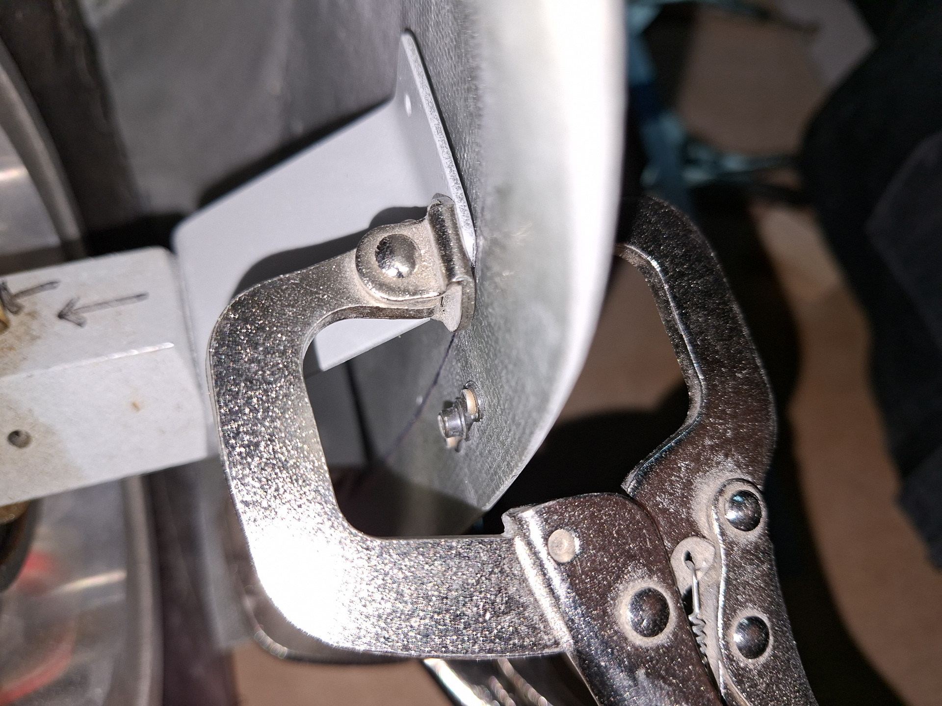
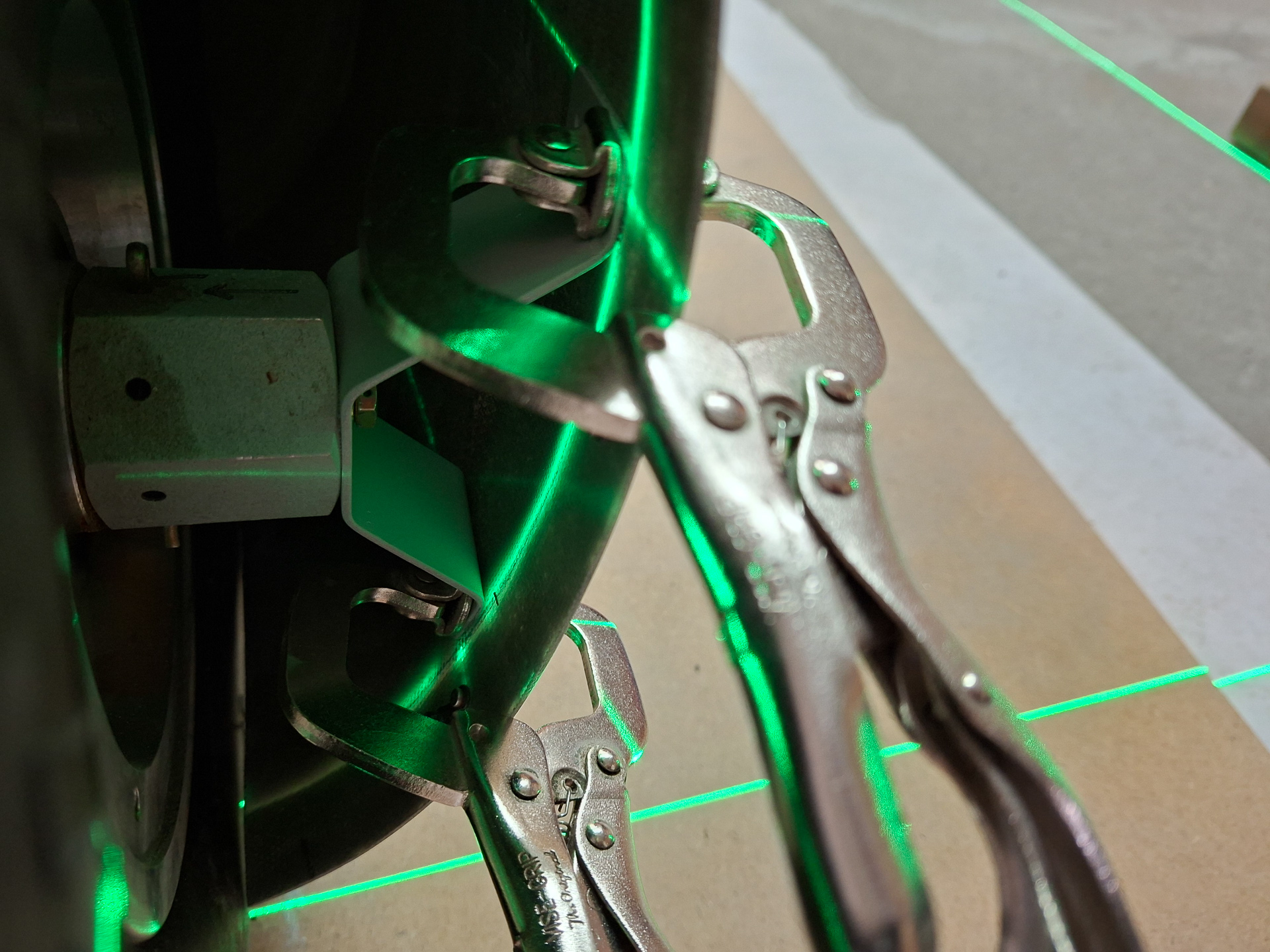
Next I used the laser level to reverify the 90° position of the outer bracket in relation to the longeron.
You draw a 1 inch offset line on the inside of the wheel pant and then clamp the bracket to the epoxy fairing.
For some reason, it does not perfectly line up although I measured 20 times for a horizontally level wheel pant fairing.
This is what was causing me the most of doubt before I would drill any holes.
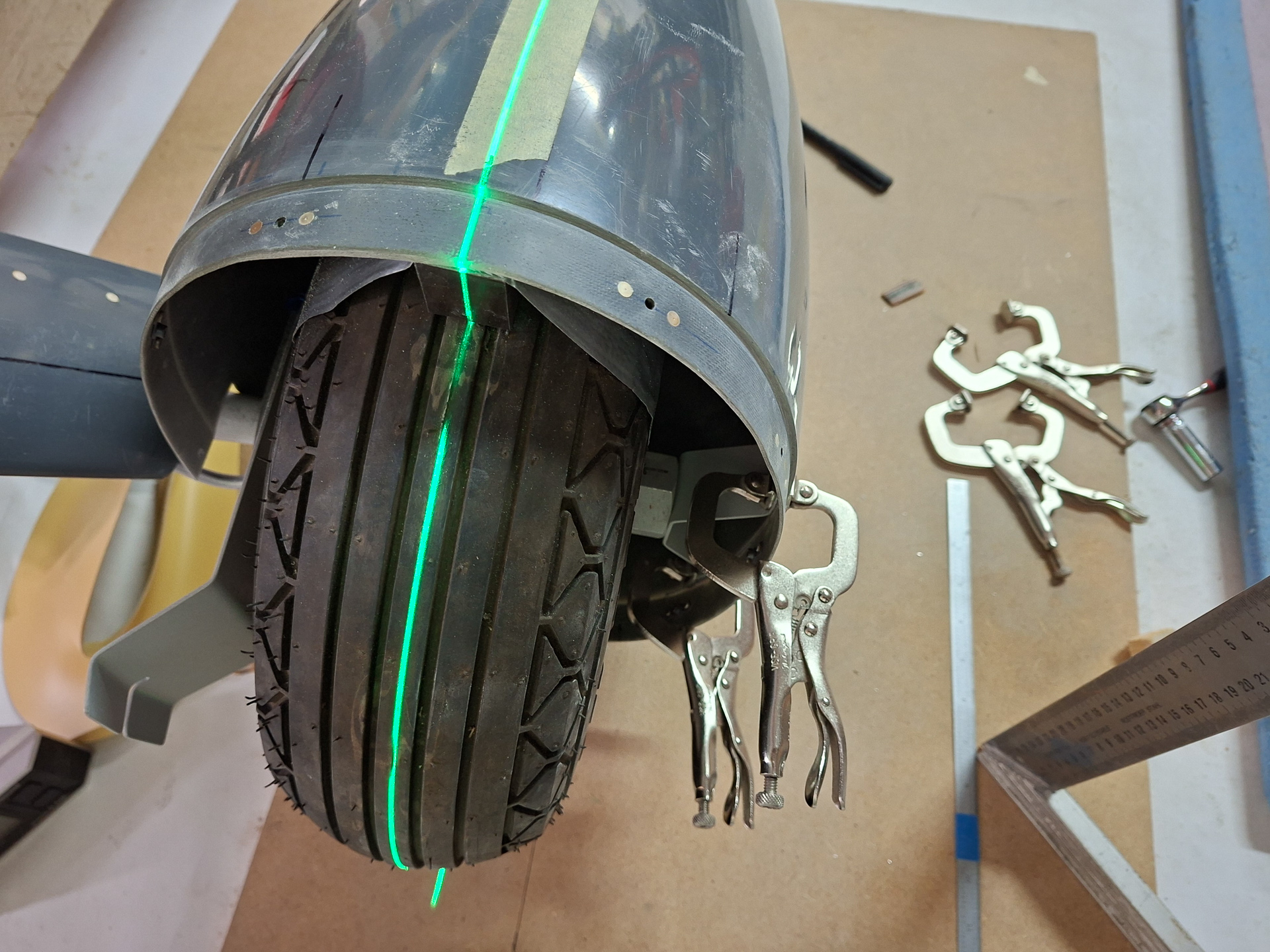
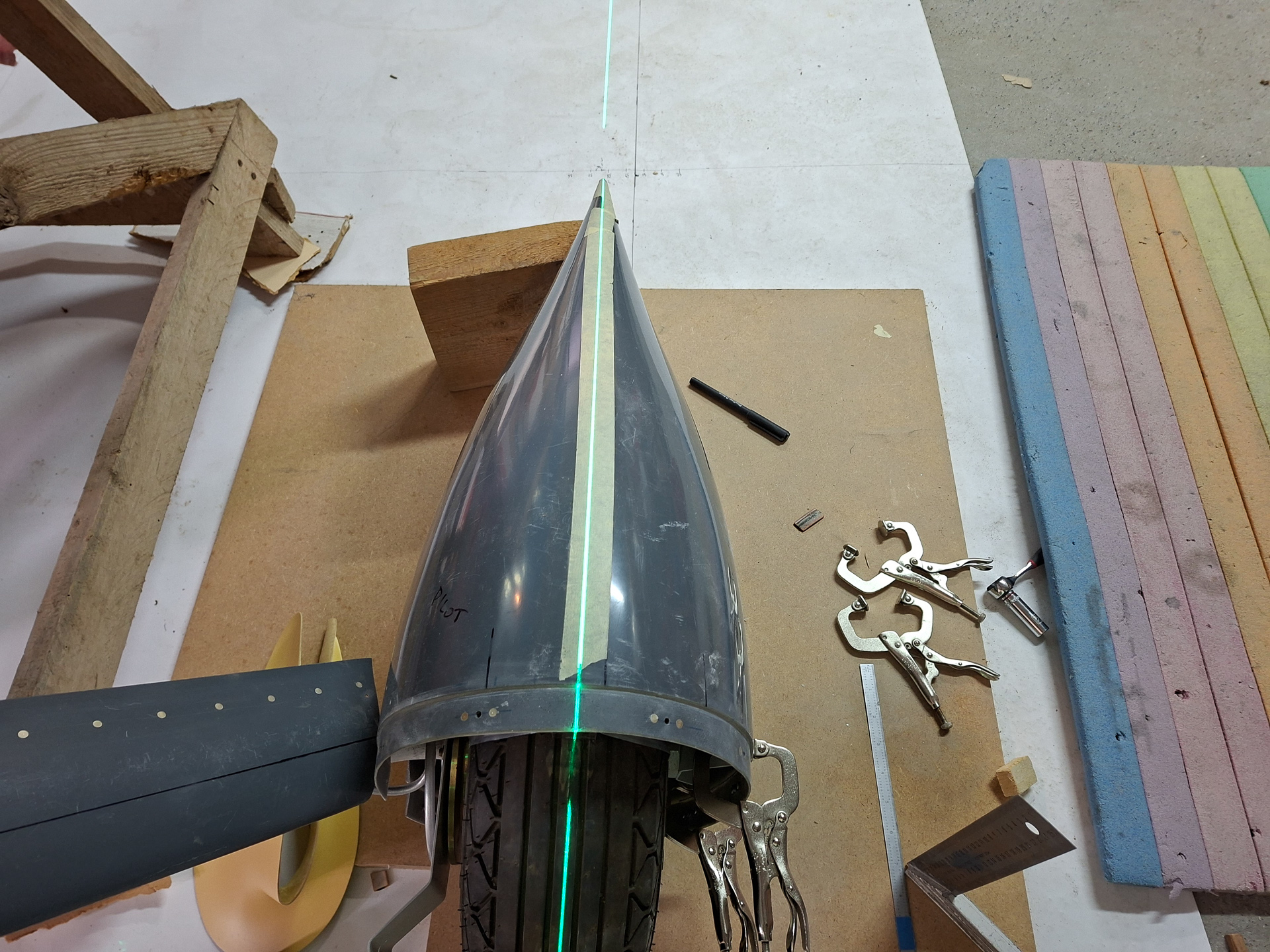
I put the laser back on and verified also on the inside with the line shining through. The 1 inch offset line is perpendicular.
This make me think there is a slight taper in the aluminum bracket. It's not much but it is there.
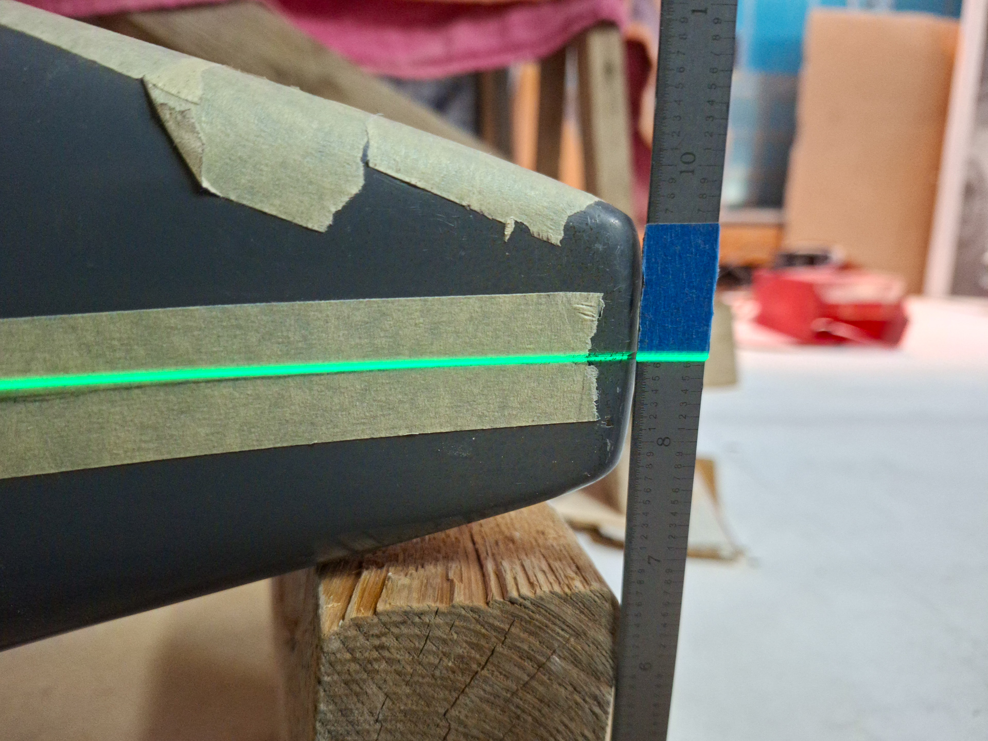
I checked again the reference height for the middle of the rearside of the wheel pant.
A whole day of measuring and cursing and not a hole drilled. These wheel pants are starting to work on my nerves.