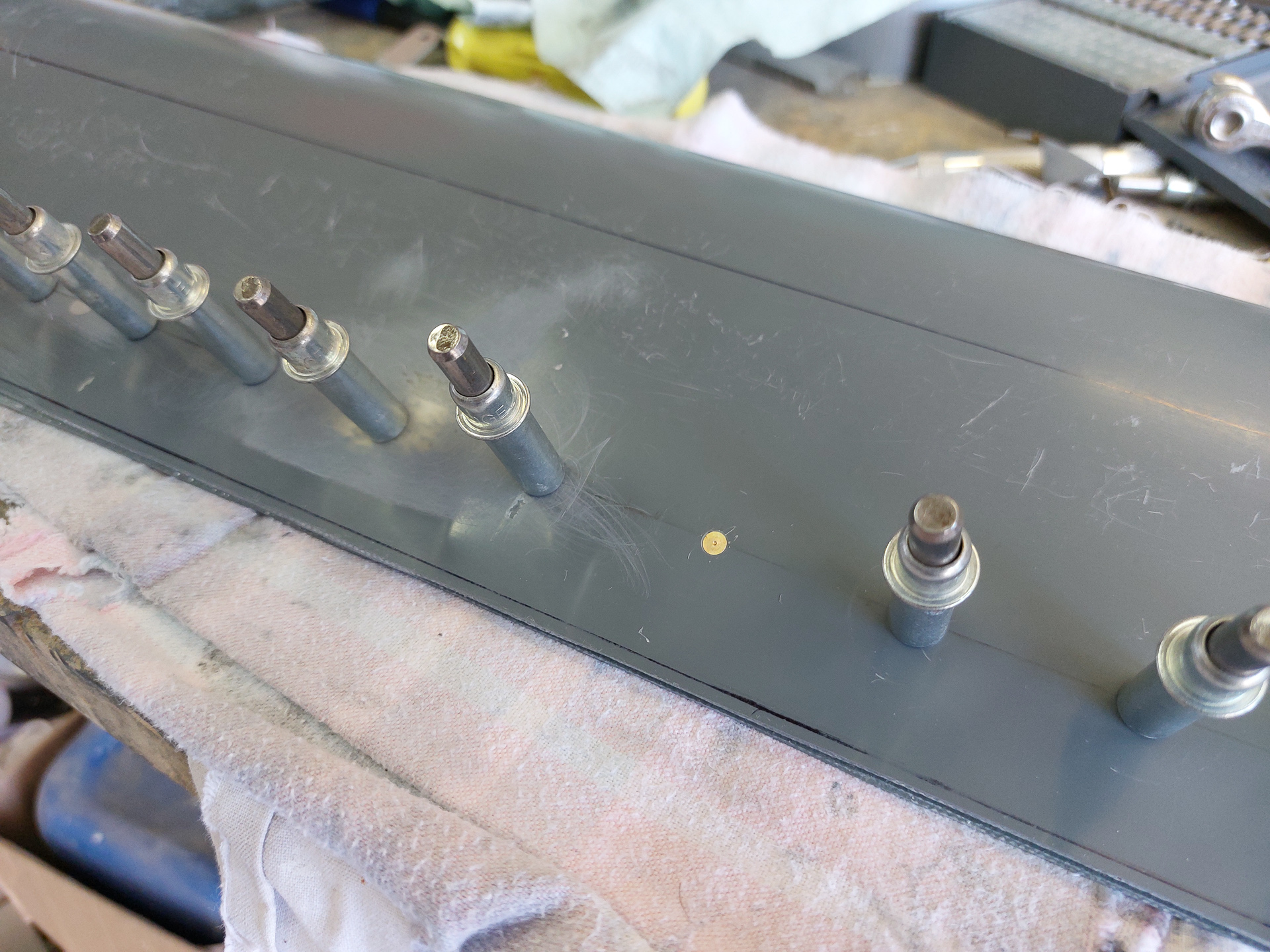
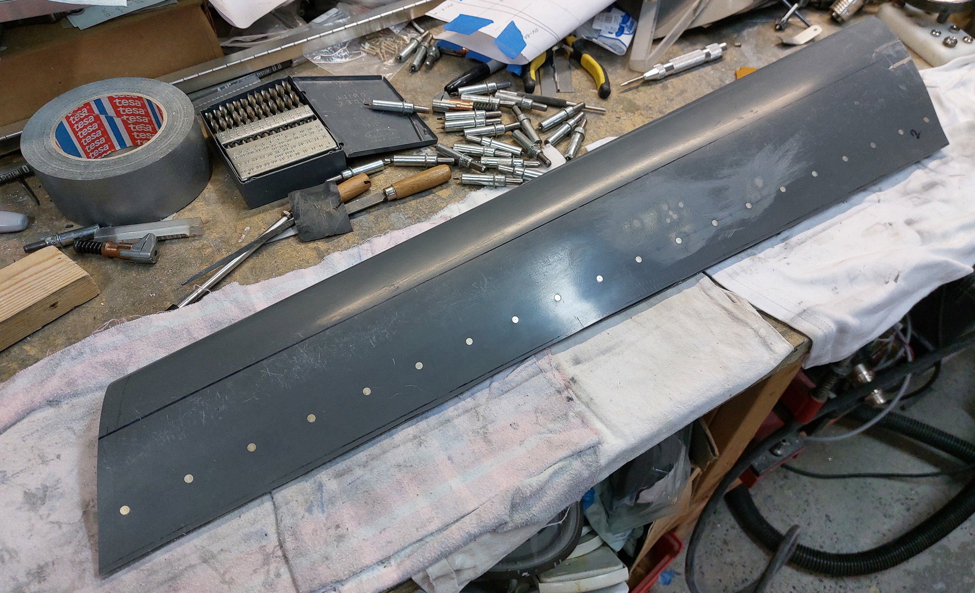
Continuing on the pilot side gear leg fairing. After all the countersinking was done, I started rivetting the line of rivets from the hinge to the fairing.
I used the pneumatic squeeze for this but have "under-set" them as per the manual. They all remain a bit thick and narrow on the shophead side. Setting them more creates a risk to create cracks in the holes while setting because of the soft and fragile epoxy material. Squeezing them was easy, you just have to pay attention that the die does not press on the hinge-eyelet and that the rivet set die is big enough to move over the hinge eyelets when fully squeezing. If you touch an eyelet, it is hard to push back and it brings the eyelet out of alignment making insertion of the pin more difficult. (ask me how I know...).
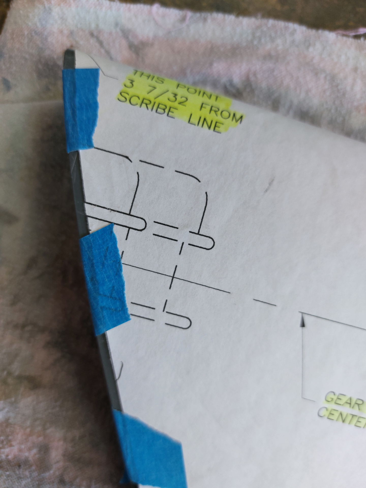
Then it was time to make the two cut out slots that will define the clamping finger on the top of the fairing. Easiest way to do this is put the paper template back on and mark the location sliding it a bit forward and marking the two cutout spots. Then moved the template a bit up and aligned with the top of the fairing and used a pinpunch to mark a drilling spot where the end of the cutout is so that I get a nice round circle at the end of the cutout.
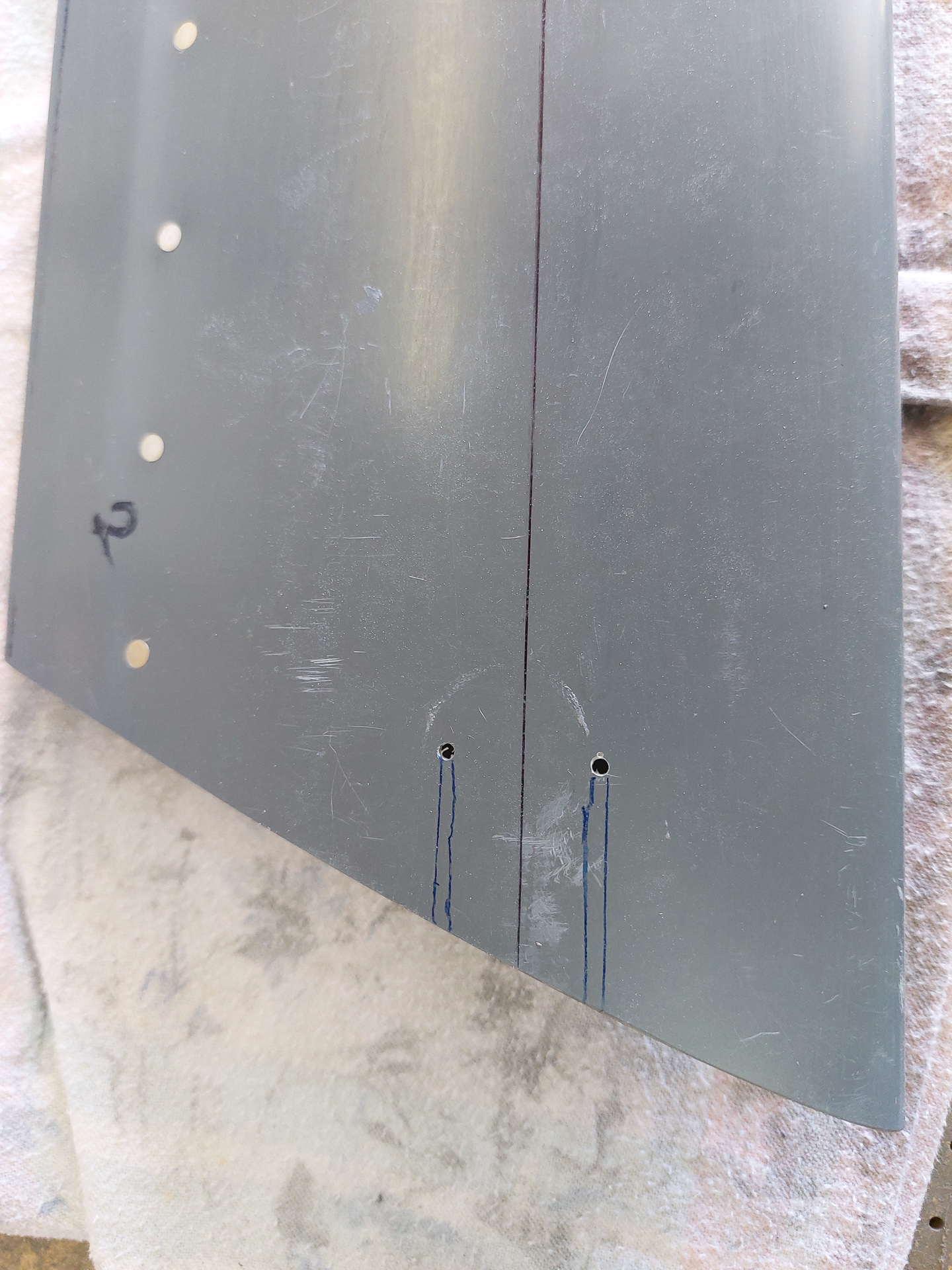
In the image below, I have both holes drilled and then reamed to #30. #30 seems to be the good size for the cutout width.
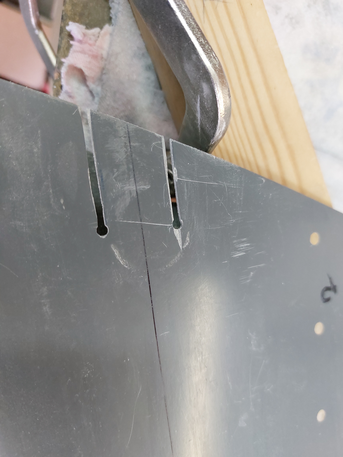
Then used a dremel tool with small cutting disc and cut along the lines into the drilled hole.
All it needs now is some key philes do smooth it out and sandpaper. Go easy on the effort put in the sandpaper work as you will still add epoxy layers later underneath the finger and that will ruin your nice sanding job and you'll have to do it over again anyway.
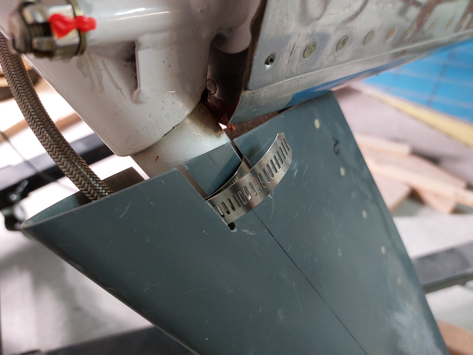
Then installed the fairing to the left gear leg. If I recall well, I think I used a HW-00016 1.06" steel hose clamp. The clamp grabs front and back fingers and makes sure the fairing doesn't slide down. Then final alignment will be determined by the intersection fairings after all the alignment measuring will be done. Unfortunatly I need the lower cowling attached in order to do this alignment and I'm not at that point yet. So another point on the list of "to be completed" items.
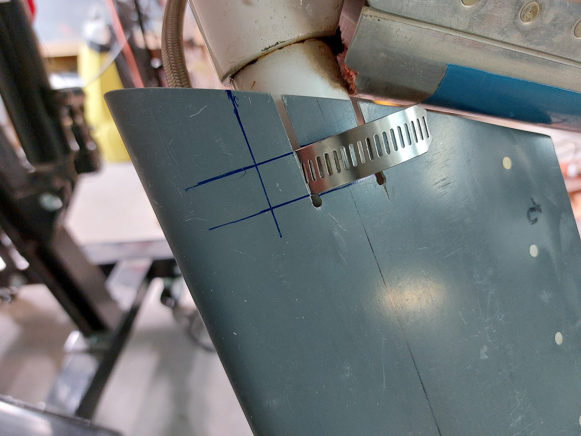
When the clamp was in the desired position, I marked the location in front of the gear leg on the fairing where the set screw for the clamp needs to be accesible. the screw will be located on the front side of the gear leg. I may be a bit tricky to route the brake line over it but I'll deal with that when I remake the brake line.


