

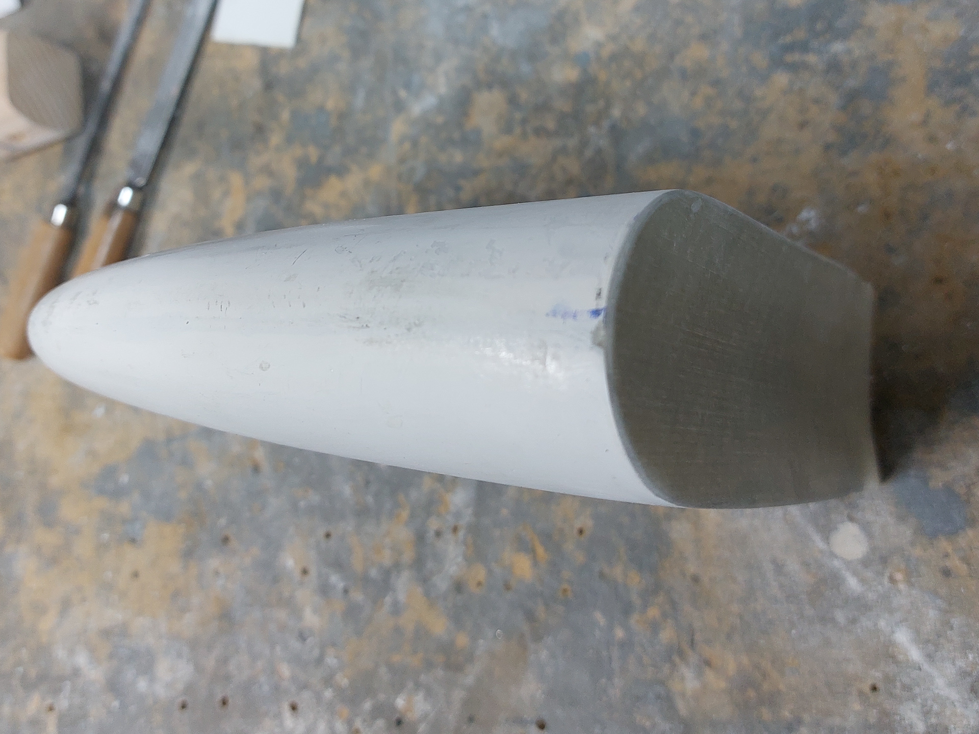
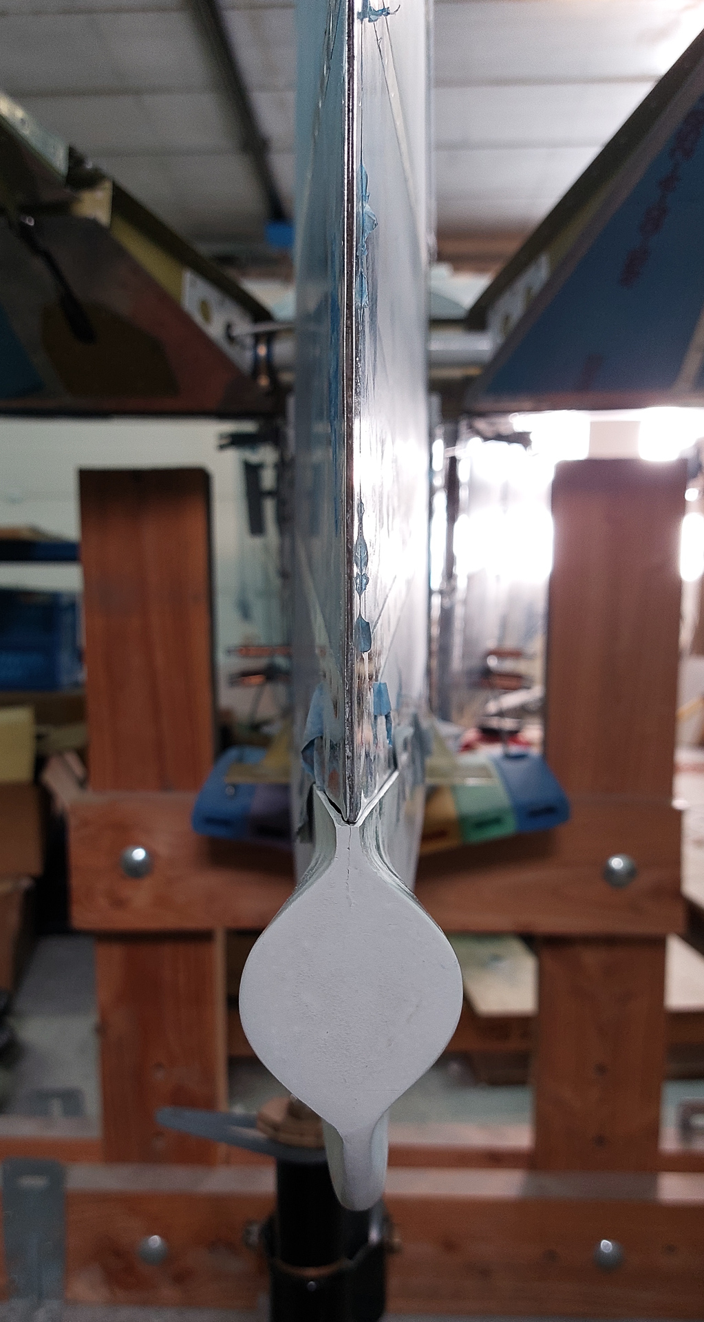
Final steps of working on the vertical stabilisor tip. All epoxy has cured and I have polished and sanded the edges of the new epoxy rear cover.
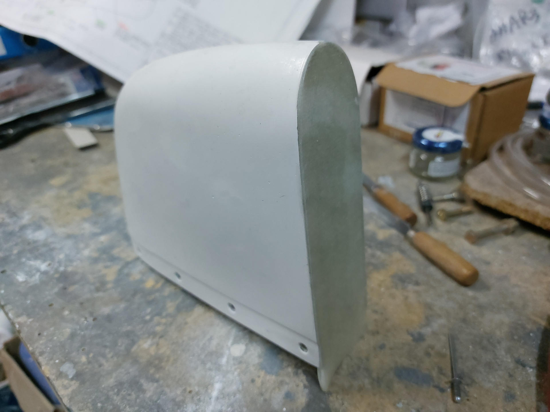
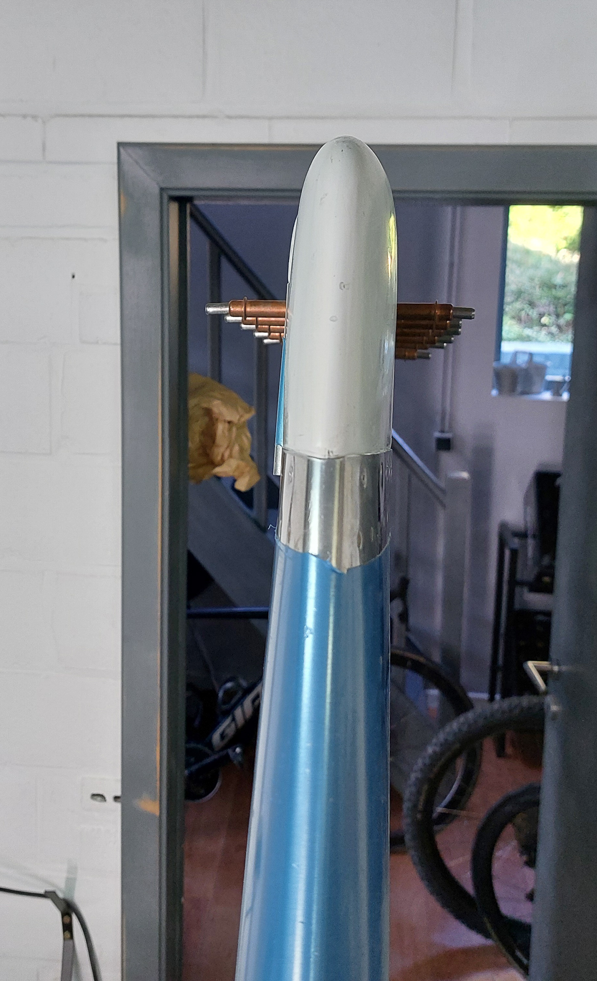
The curve is nice and the surface as smooth. This can now be permanently attached to the top of the vertical stabilisor.
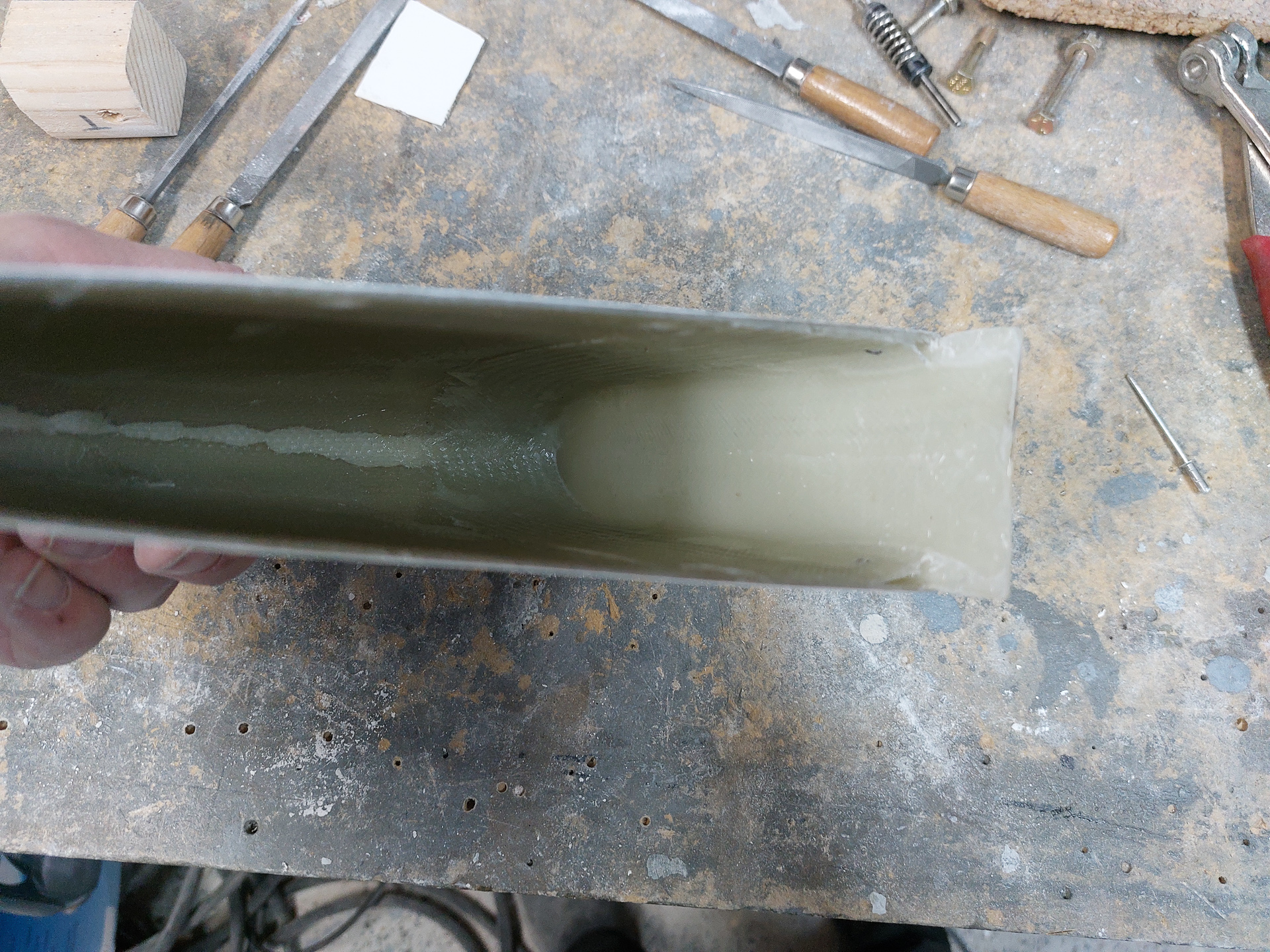
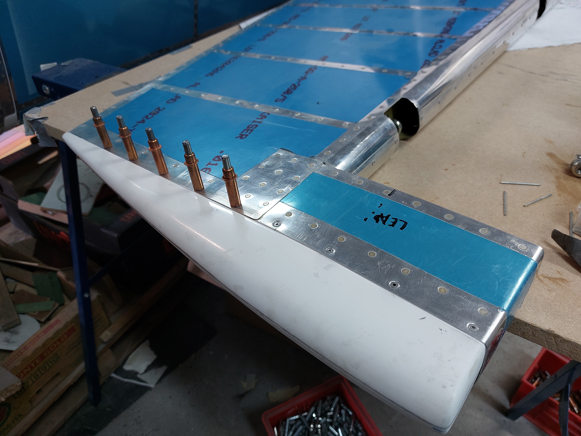
Cleaned up the inside a bit and made sure no dust or particles are left inside before pop rivetting. There is no more way to access the inside once the rivetes are in.
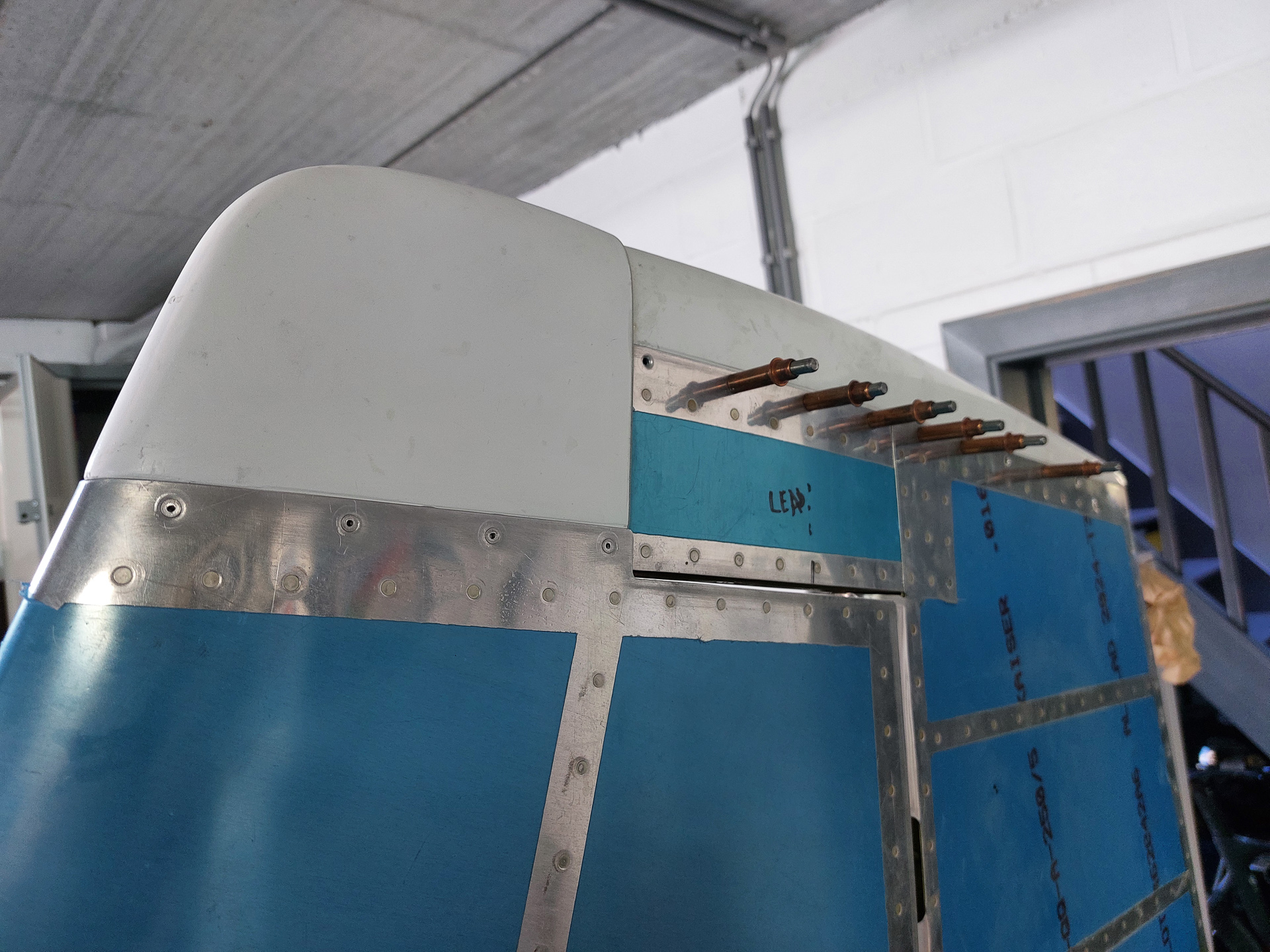
Deburred and dimpled the drilled holes in the top VS skin.
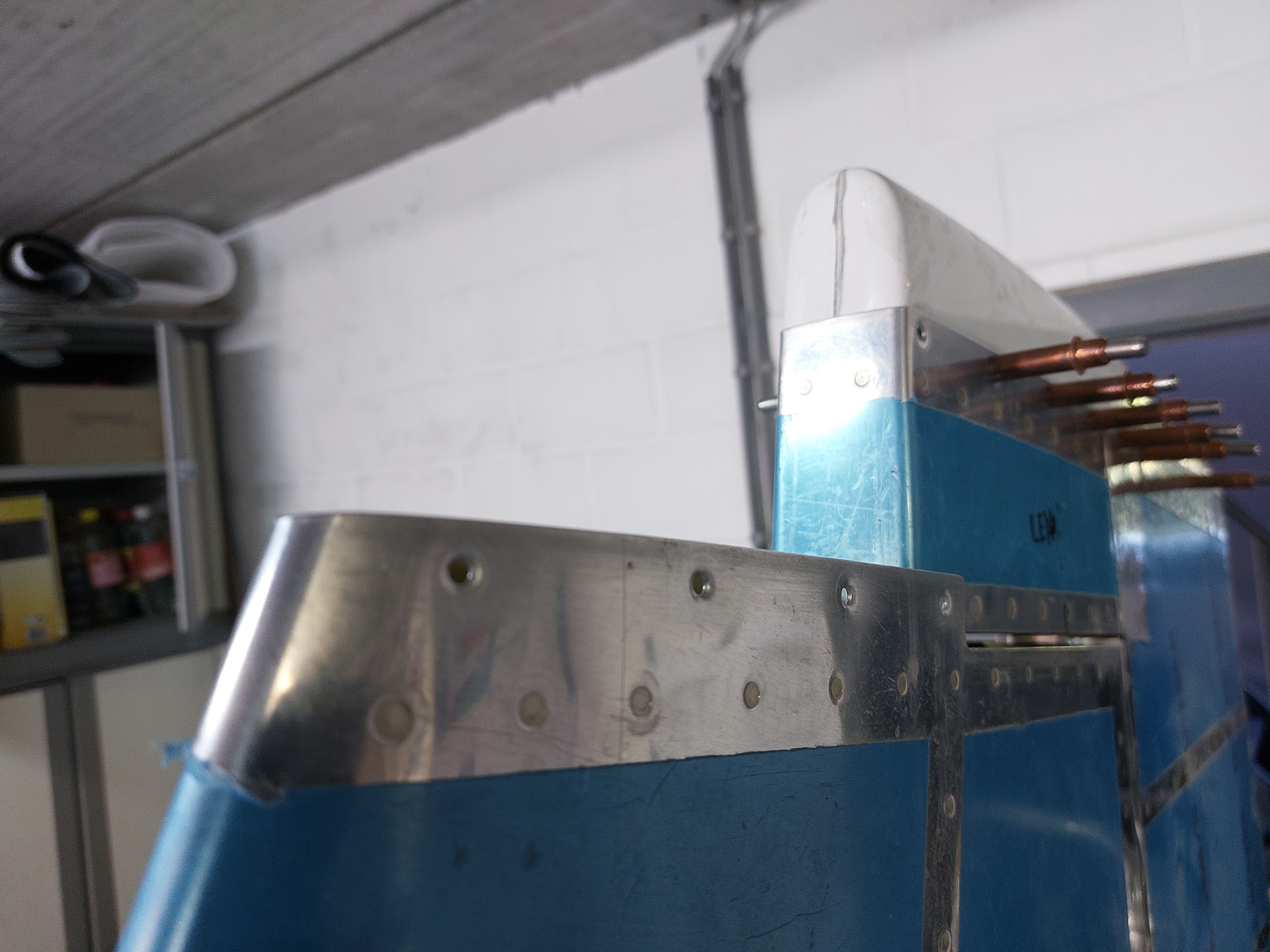
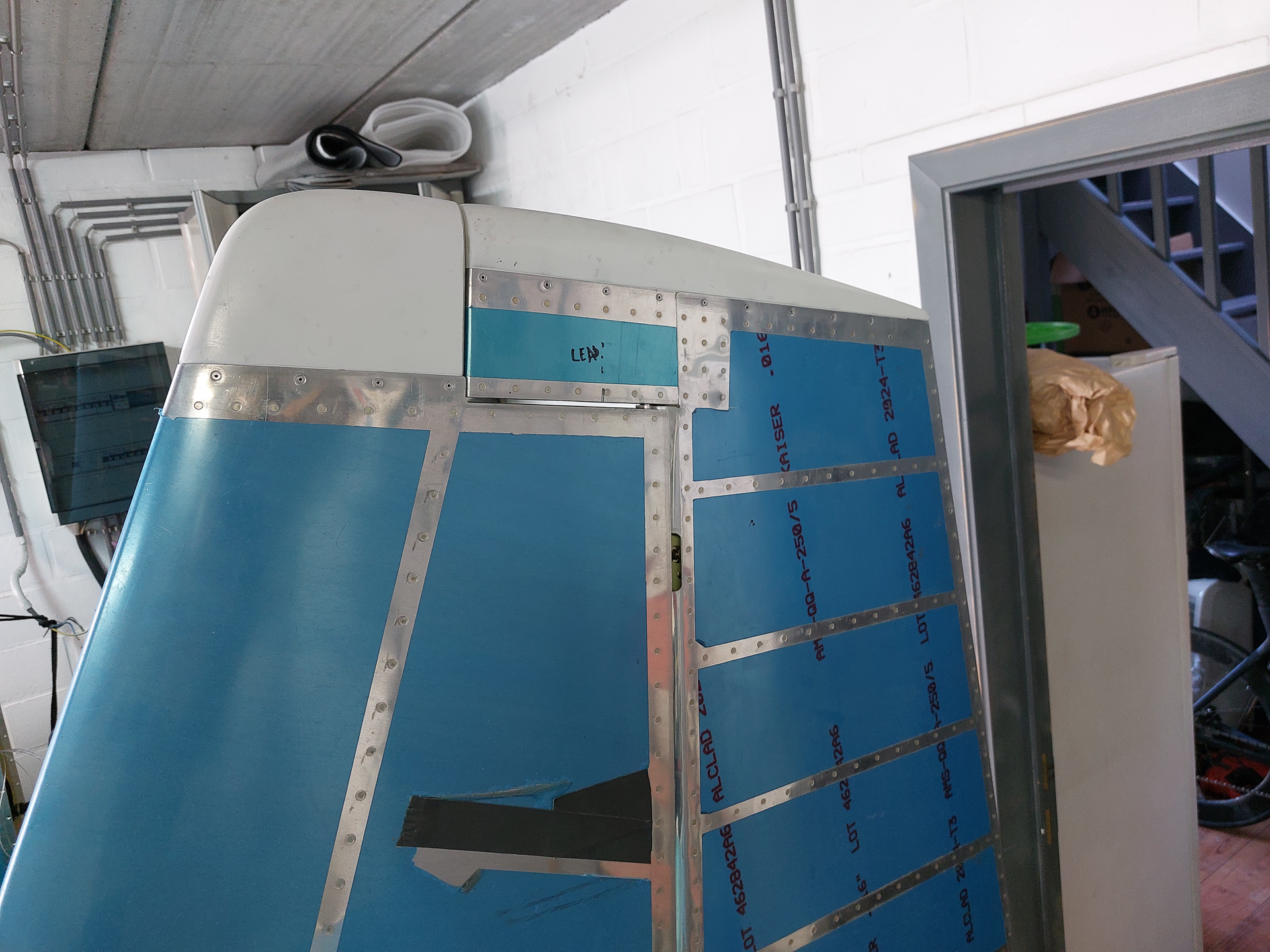
Installed the tip and verified final alignment. All lights green so I pulled out the pop rivetter and installed the CS4-4 rivets.
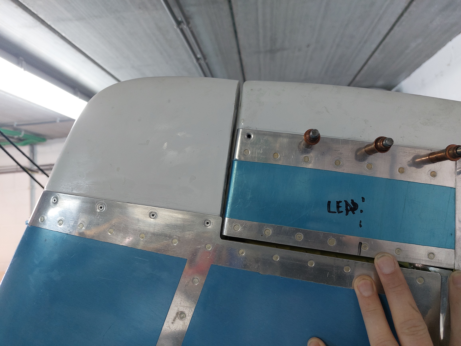
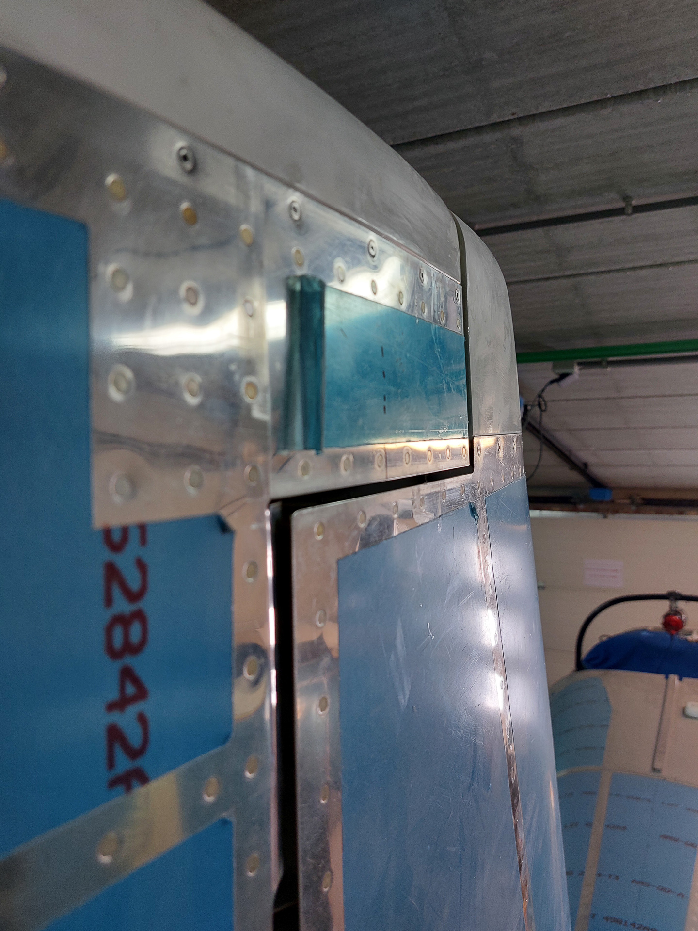
The shape looks very good. The rudder had a little swing when taking the picture but when in line, the alignment between rudder and VS tip is as required.
The gap between the rudder and tip is straight and sufficient for the 1/8" tot 3/16" minimum gap as prescribed in the plans. There is no specific value for the VS tip but I assume it follow the same gap specification as is given between the HS tip and elevator as indicated on DWG 3.
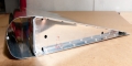
Next I verified the inside of the R-909 rudder tip. As with the elevators, I installed an aluminum reinforcement strip on both sides to facilitate and strengthen the grip of the pop rivet.
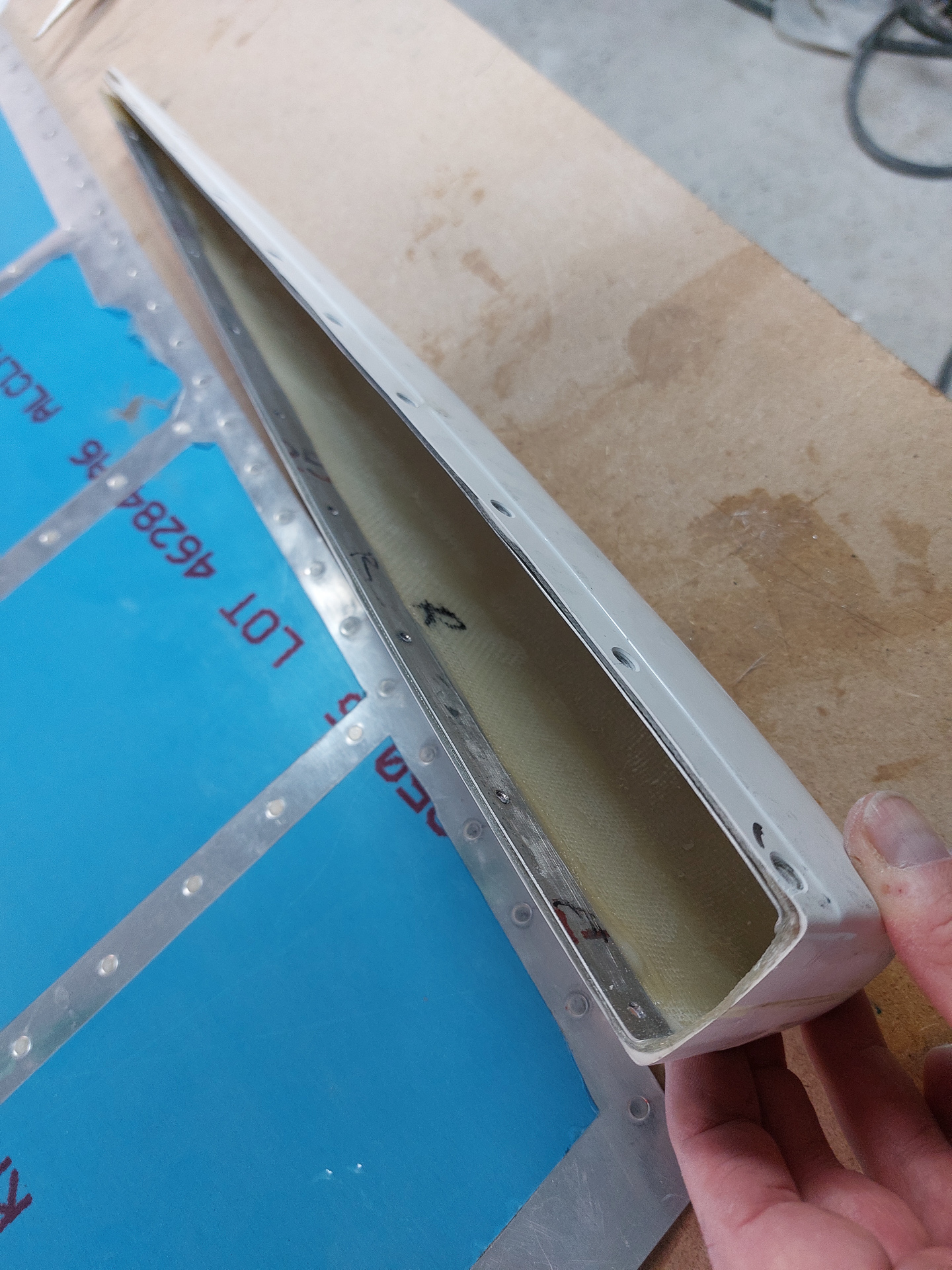
I first re-ensured the AN365-1032 nuts on the counterweight were properly thight and then final installed the rudder tip with CS4-4 pop rivets.
Re-attached the rudder and admired the result.
This looks so damned cool. Finally is starts to look like a finished airplane tail.
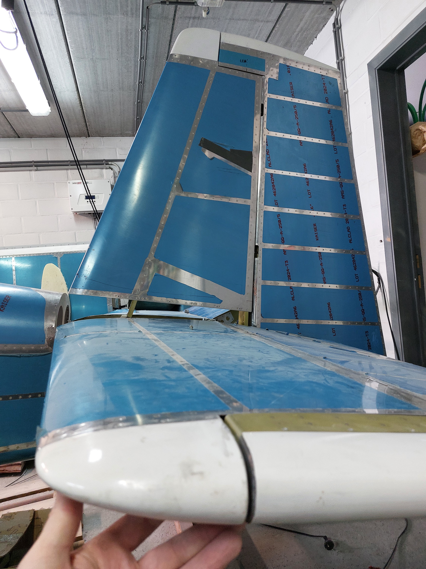
Some more alignment shots.
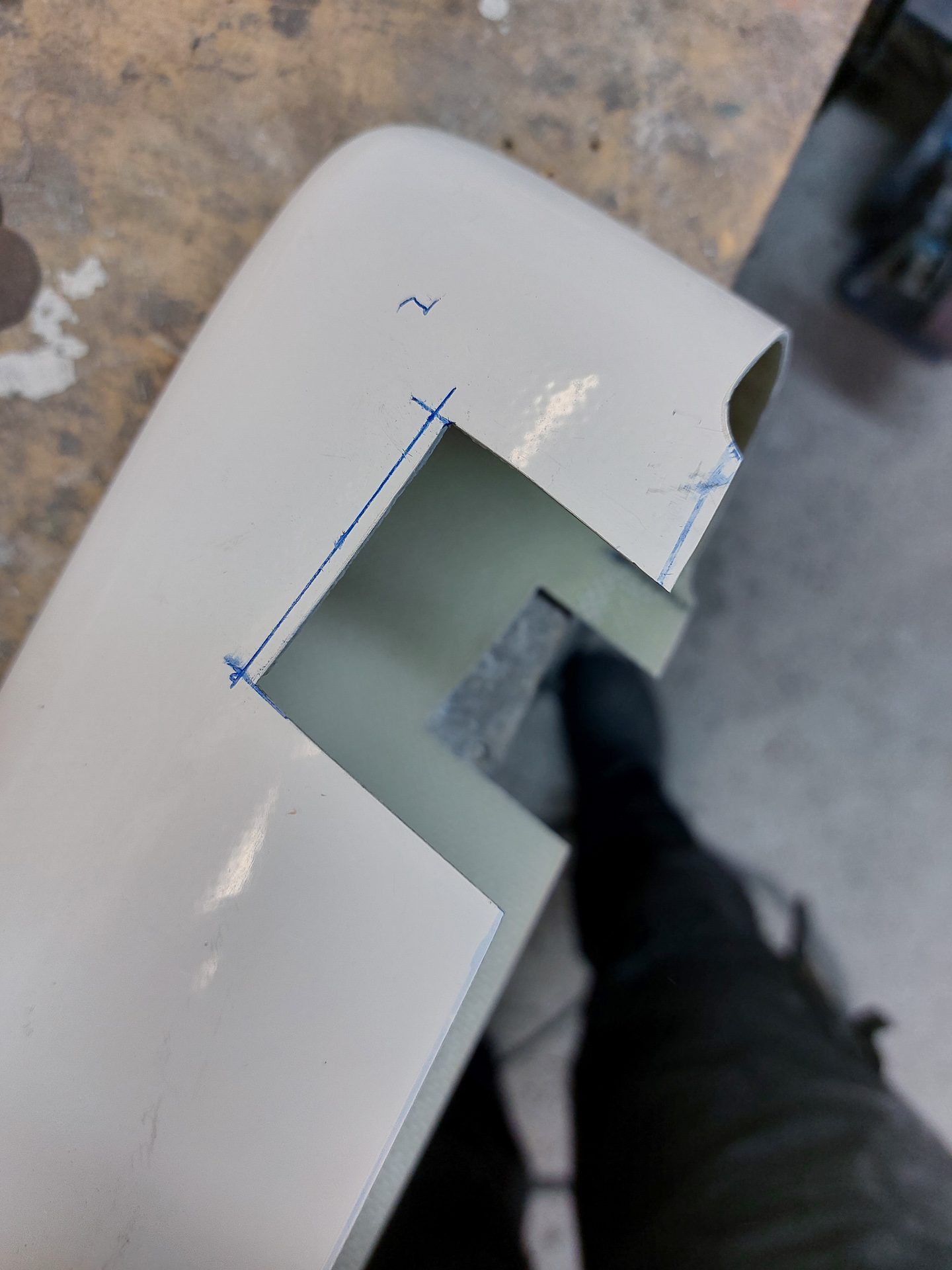
Then returned to the R-911 rudder bottom fairing. The is some more cutting and tweaking to do here in order to get a snug fit. I had to remove some more of the horn cut out.
Having to remove more had everything to do with the spacing that you want between the rudder bottom fairing and the tail spring wheel.
Without this additional cut, the rudder fairing was almost touching the tail spring. On a hard landing this would shatter the rudder fairing and potentially damage the rudder.
I wanted at least a 1/2" clearance between the rudder fairing and the tailspring to be on the safe side.
I reinstalled the fairing after cutting and checked the alignment and straightness of the fairing in relation to the rudder aft line. This looks fine for me.
The clearence is good. All the cutting has left a bit of a gap in front of the rudder horn but I will close that with some lay-up of fibre once the R-911 rudder bottom is drilled to the R-918 bottom attach strip.
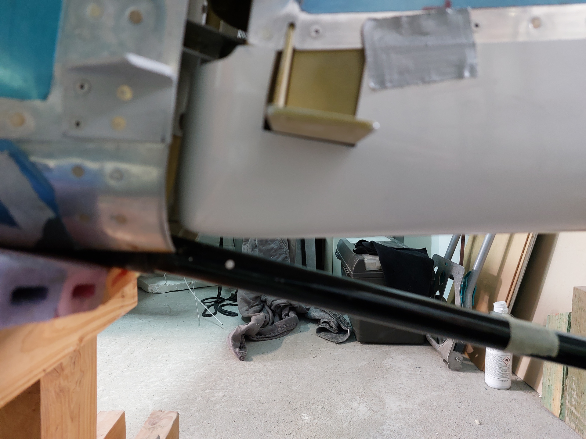
I also drilled a 1/4" drainage hole at the low point (forward of the rudder fairing) to allow water to drain out of the rudder bottom. The front of the rudder is open where the rod end bearings attach and the rudder bottom fairing acts as a bucket that will collect all the water coming in if there would not be a draining hole. Remember that you might end up in rain and water can quickly pile up in the rudder bottom as it runs down the rudder front spar.


