
Today was a really big day on the building project. I remember how I have always checked on other builders websites and social media when they came at the point of working with the engine. It always seemed so far away for me at that point. Now, it's finally that day where my own engine work is starting and I can't tell you how excited and jacked up I am about this. After a lot of elaboration and a failed search for a used engine, I decided to buy a brand new Superior XP IO-360-A1AD2 engine. It's 180hp and fuel injected with classic magneto's.
The engine was ordered at PMM Wingservice in Herentals and they will also assemble and test run it.
The advantage of having it assembled and installed before it's being test run is that time up to the first flight is not critical. As the engine has not run yet, there will be no risk of corrosion if it stands still for too long. The engine will be test run only few weeks before the actual first flight. The disadvantage off course is that the engine will have to come off again prior to flight.
It took about a year for the engine to arrive and today was the planned day that it would be assembled at PMM.
I was very lucky that they allowed me to be present during the assembly work so I really could witness how the engine came together.
Here is an image at the very beginning with the engine case in halves.

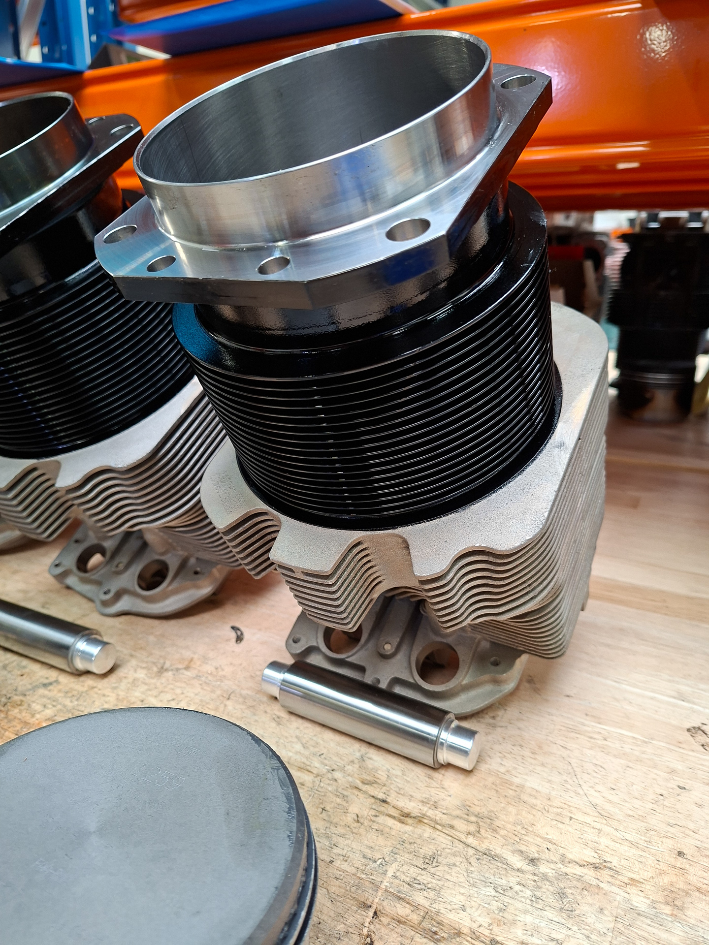
The crankshaft pusher arms that push the piston heads up and down and some pistons and cylinders.


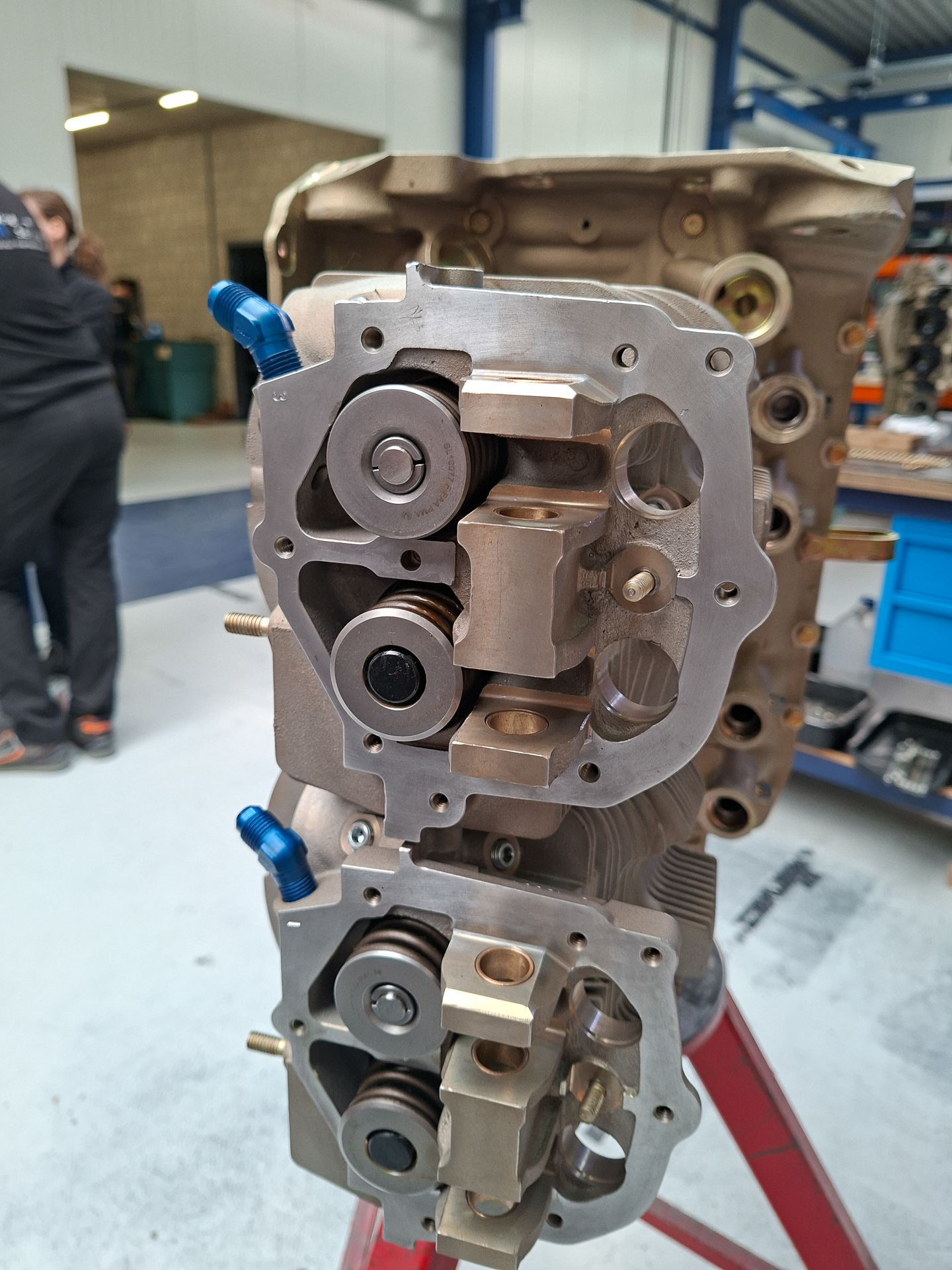
This is how a cylinder head looks like from close by. A pin slides through the bottom side to attach the crankshaft push arm. The rings on the sides of the piston is what seals the compression chamber. The main reason for running-in the engine is because these rings need to "set" themselves to the cylinder walls. This is done by running the engine for some hours at 80% power at straight and level flight with good cooling. Failing to do so might lead to oil consumption which is hard to get out once it's there.
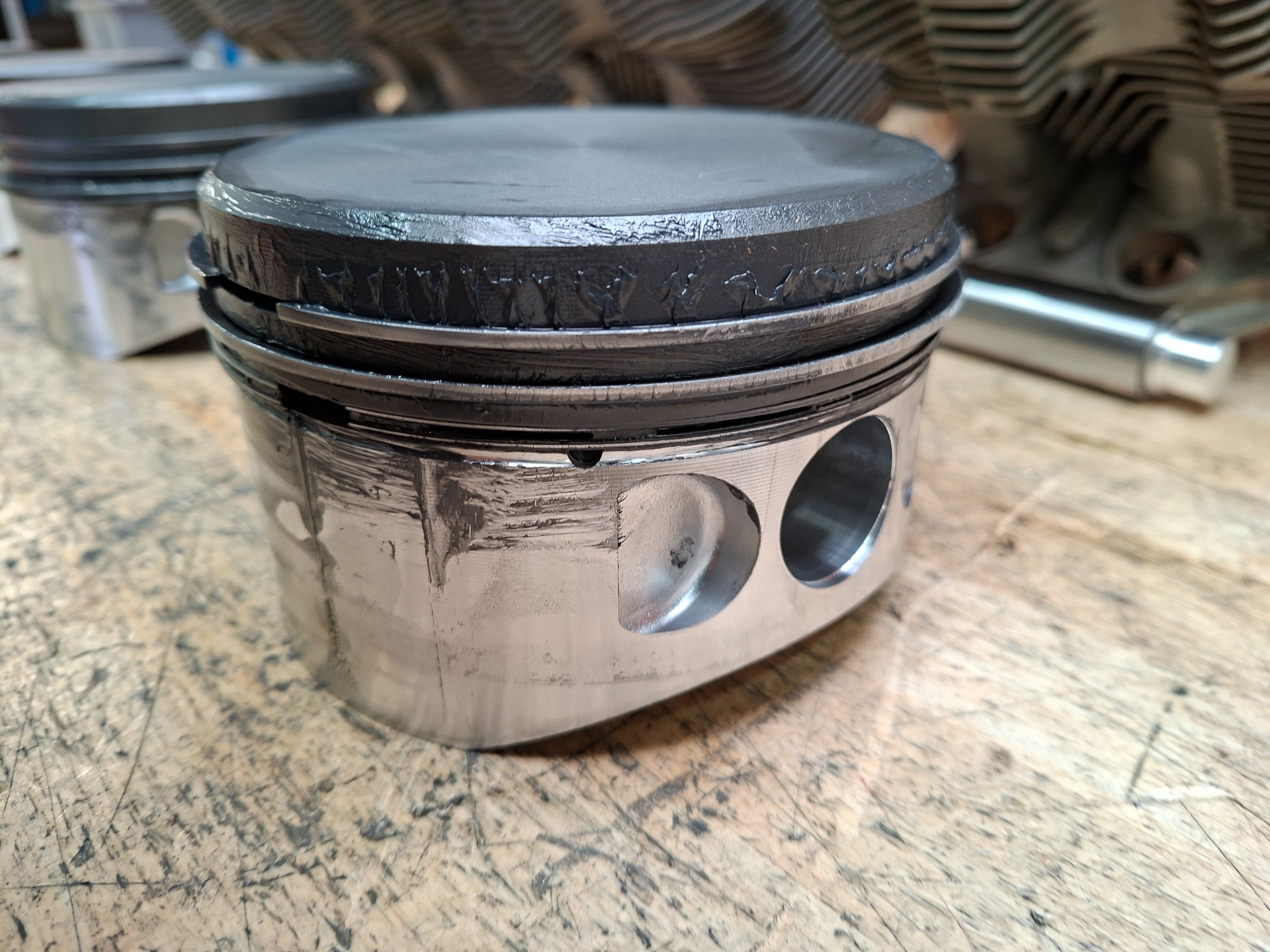
Here 's a picture of a cylinder head.
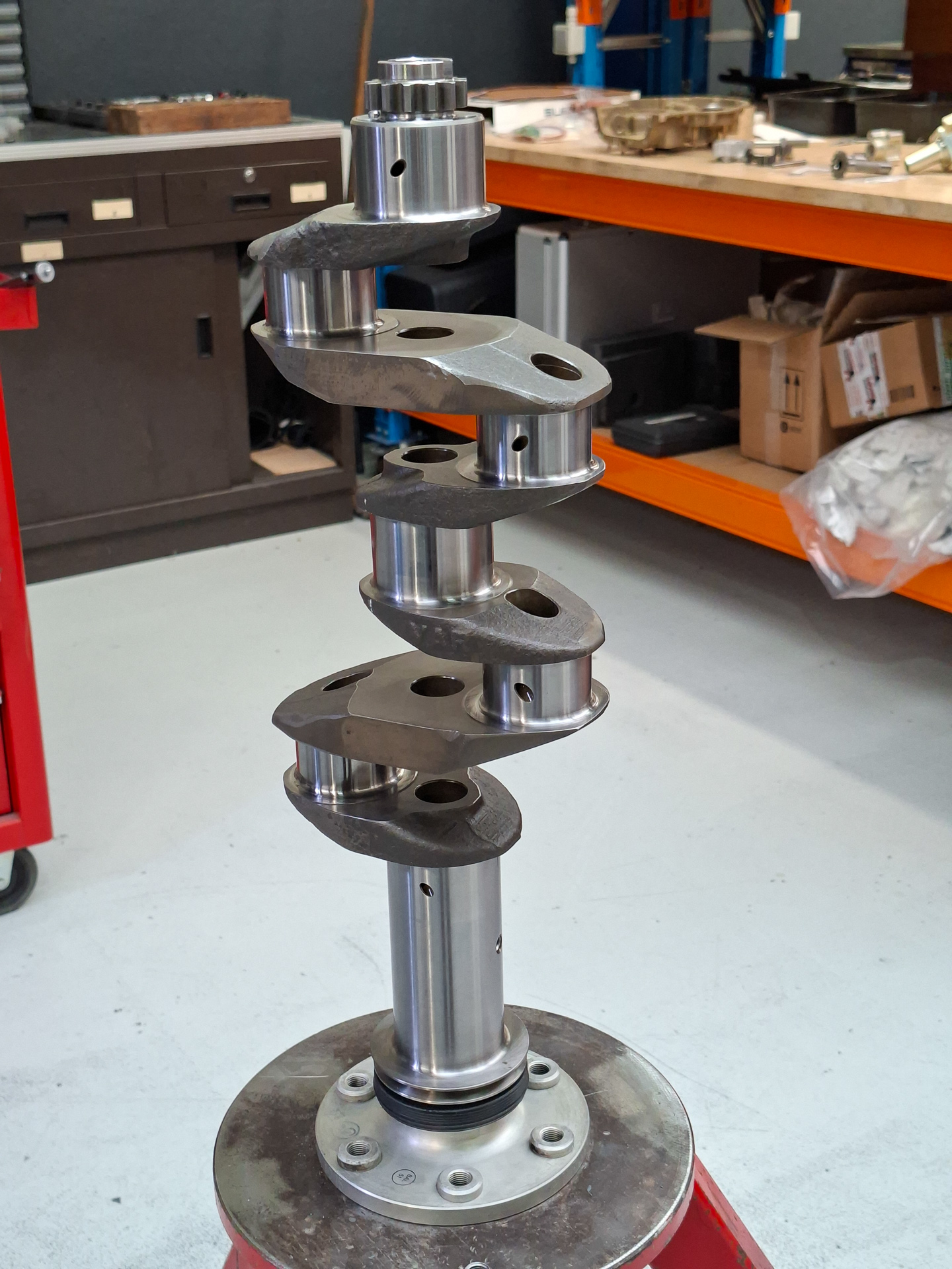
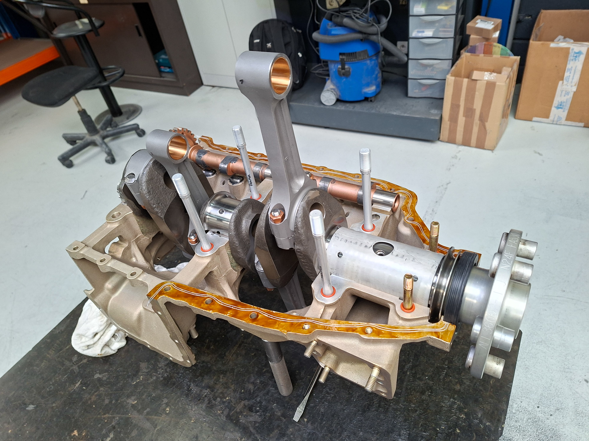
The crankshaft gets placed on a stand with the prop hub down.
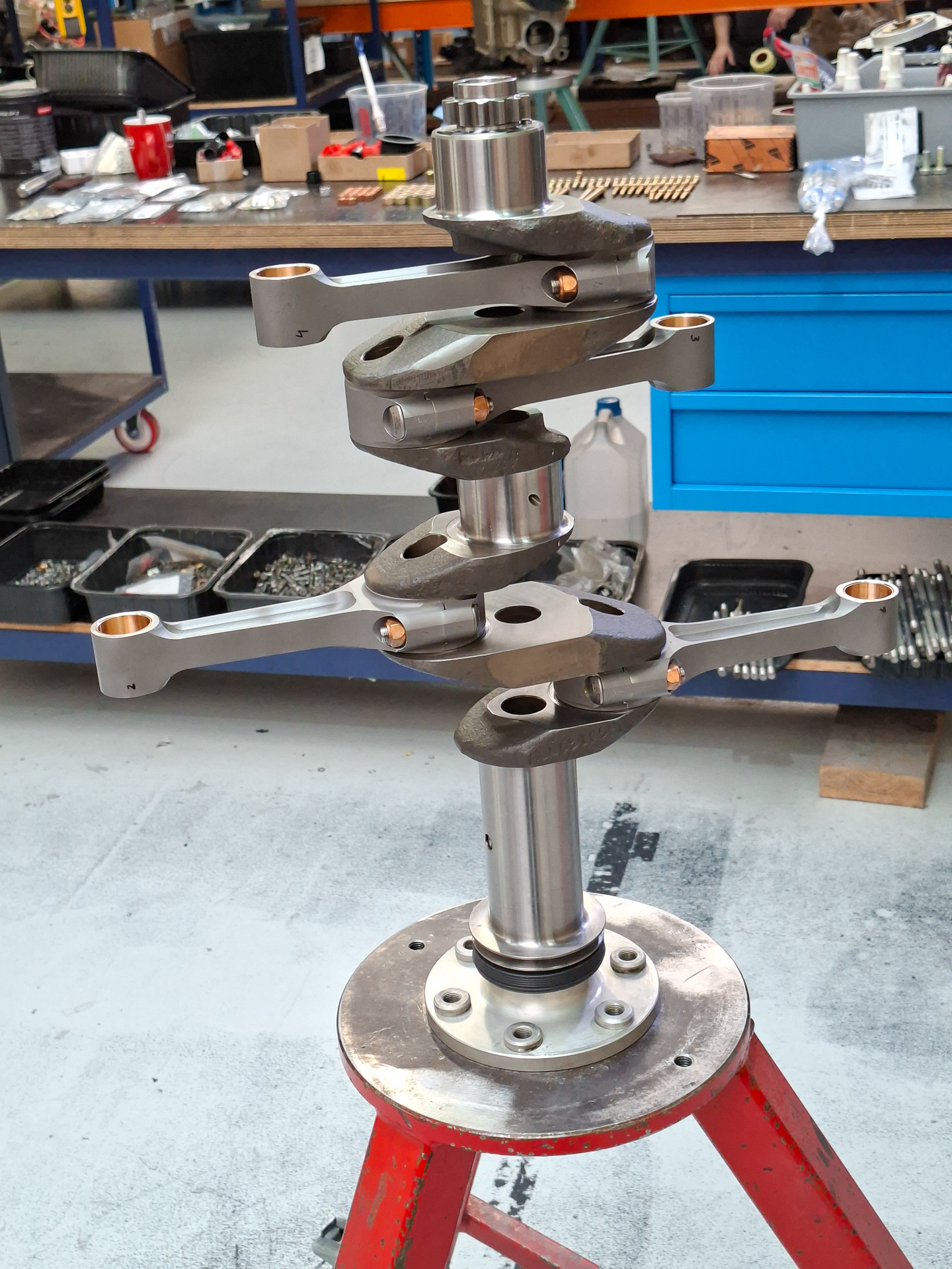
Then the pushers for the cylinders are installed on the crankshaft.
You can clearly see here that cylinder 1 and 3 will be at top center while 2 and 4 will be at the down position.
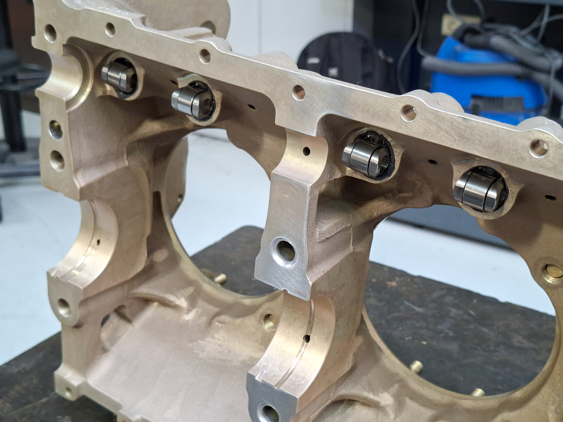
Next they install the roller tappets in the engine case. This is a unique system with Superior engines and a great improvement compared to classic Lycoming engines.
The 4 rollers you can see here in the top of the image are the connections that run on the camshaft. With classic engines, the pushrods that operate the cylinder valves are in direct contact with the camshaft. As these are not rounded, there is wear and grinding between the pushrod and the camshaft lob. With roller tappets, the pushrods "roll" over de camshaft lob which causes much less wear and possible corrosion points.
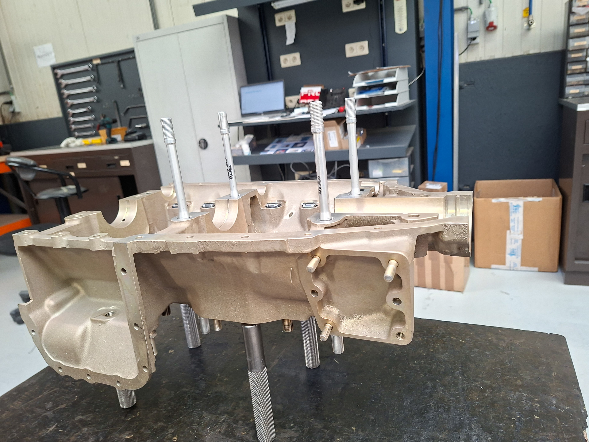
Next, the through-bolts are installed. As the name reveals, these are bolts that run through the engine case and are squeeze the case together.
Small detail I learned is that when you loosen one of these bolt on one cylinder, you need to re-torque both sides when fastening again.
Then the crankshaft and camshaft are lubricated and installed in the case. A sealant is applied on the sides and also 2 nylon wires which help preventing oil leaking.
Then the engine case is closed.
By the way... in the movie you can see Patrick Van Dooren and his son Kobe. Patrick is owner of PMM WIngservice and a local legend in the engine construction and maintenance world in Western Europe. It's an honor having a guy like that working on your engine.
the cylinders are installed by sliding the cylinder cases over the pistons while the side rings are clamped inwards.
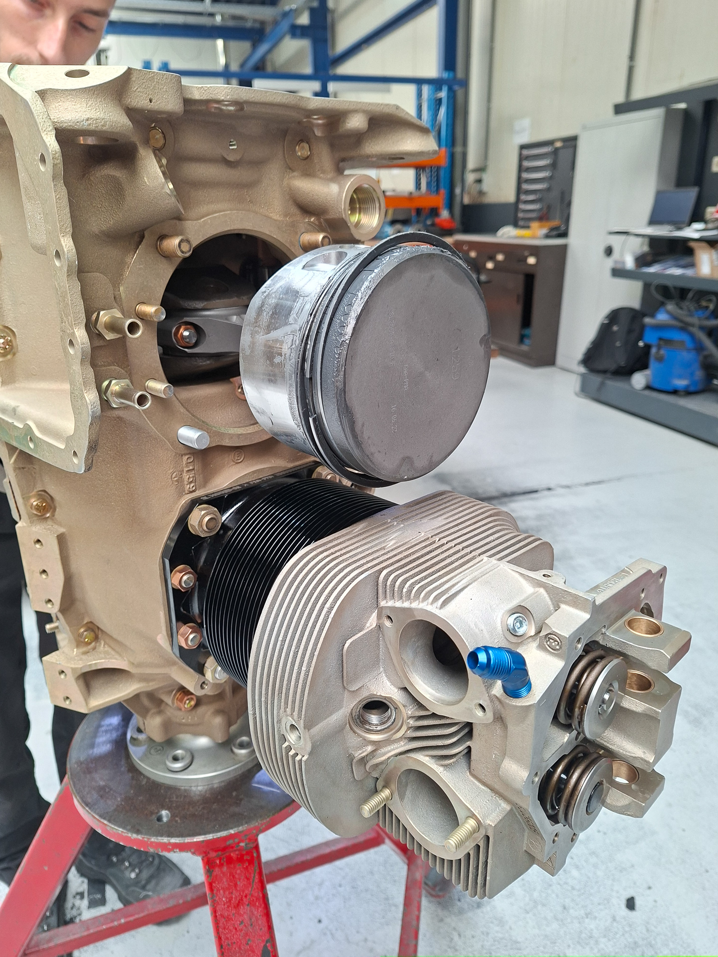
The image below shows the top side of the cylinders. You can see the 2 round valve heads.
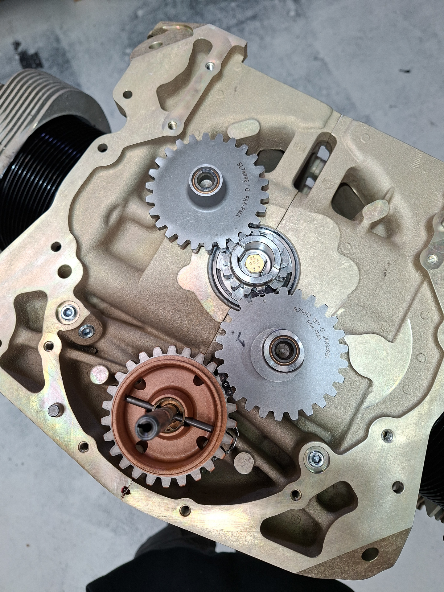
In the back, you find the gear box that drives various peripherals like the magneto's, suction pump, engine pump and the camshaft.
The small wheel in the center is the main crankshaft drive. The 2 other gray gears are driving the magneto's. One of the magneto gears connects to the camshaft gear which logically is 4 times the size of the crankshaft gear as it takes 4 rotations of the crankshaft for one full rotation of the camshaft.
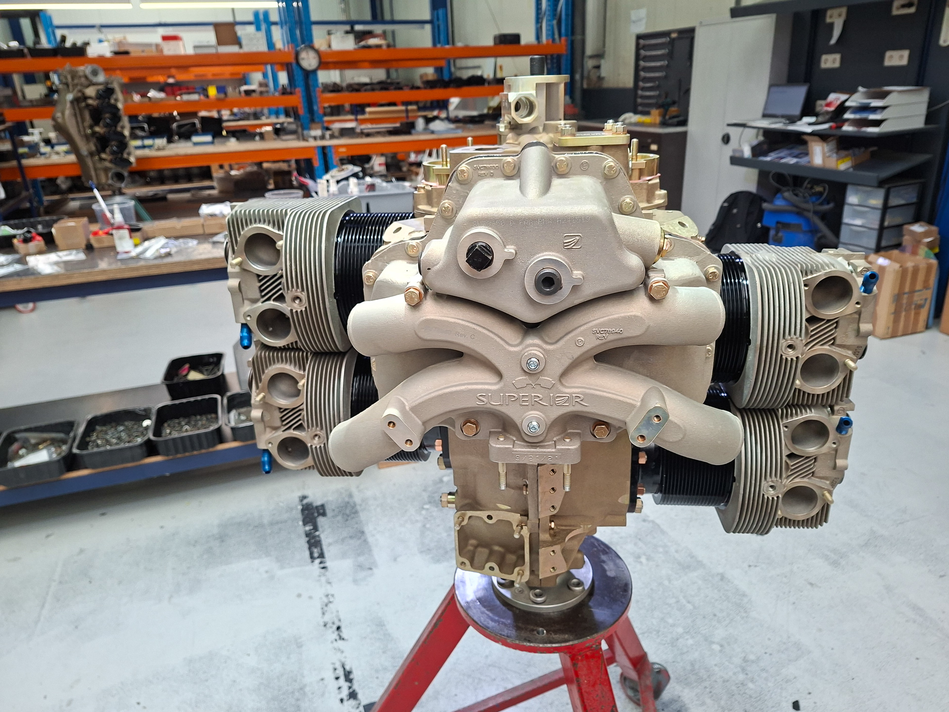
Then the cold air induction sump is installed. The top shows the oil sump with 2 oil drain points. The middle shows the 4 air intake pipes that come behind the location where the TBI (throttle body injector) will be attached.
This more or less concluded day 1. The engine covers and the engine case will now be painted and assembly work will continue tomorrow.