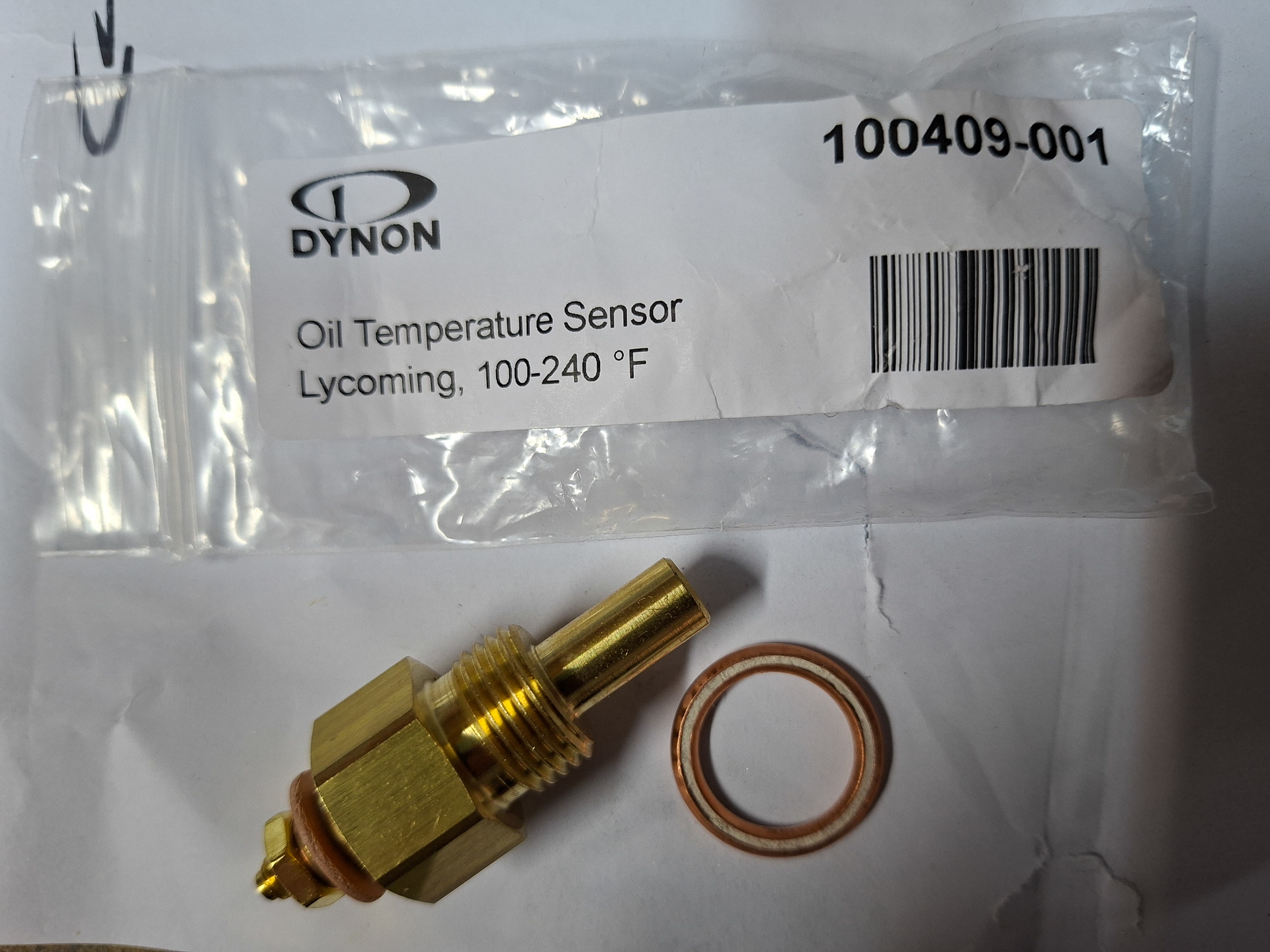
Another wire that still needs to be installed to the EMS is the oil temperature pressure sender. Dynon supplies this sensor in the EMS sensor kit. In the bag is also a copper washer that is installed between the sensor and the engine case. It's important to note that the washer has 2 sides. One side is a solid copper smooth side which is installed against the sensor (the side visible in this image). The back side looks rougher and has a machined side to it. That side had to be against the engine case.
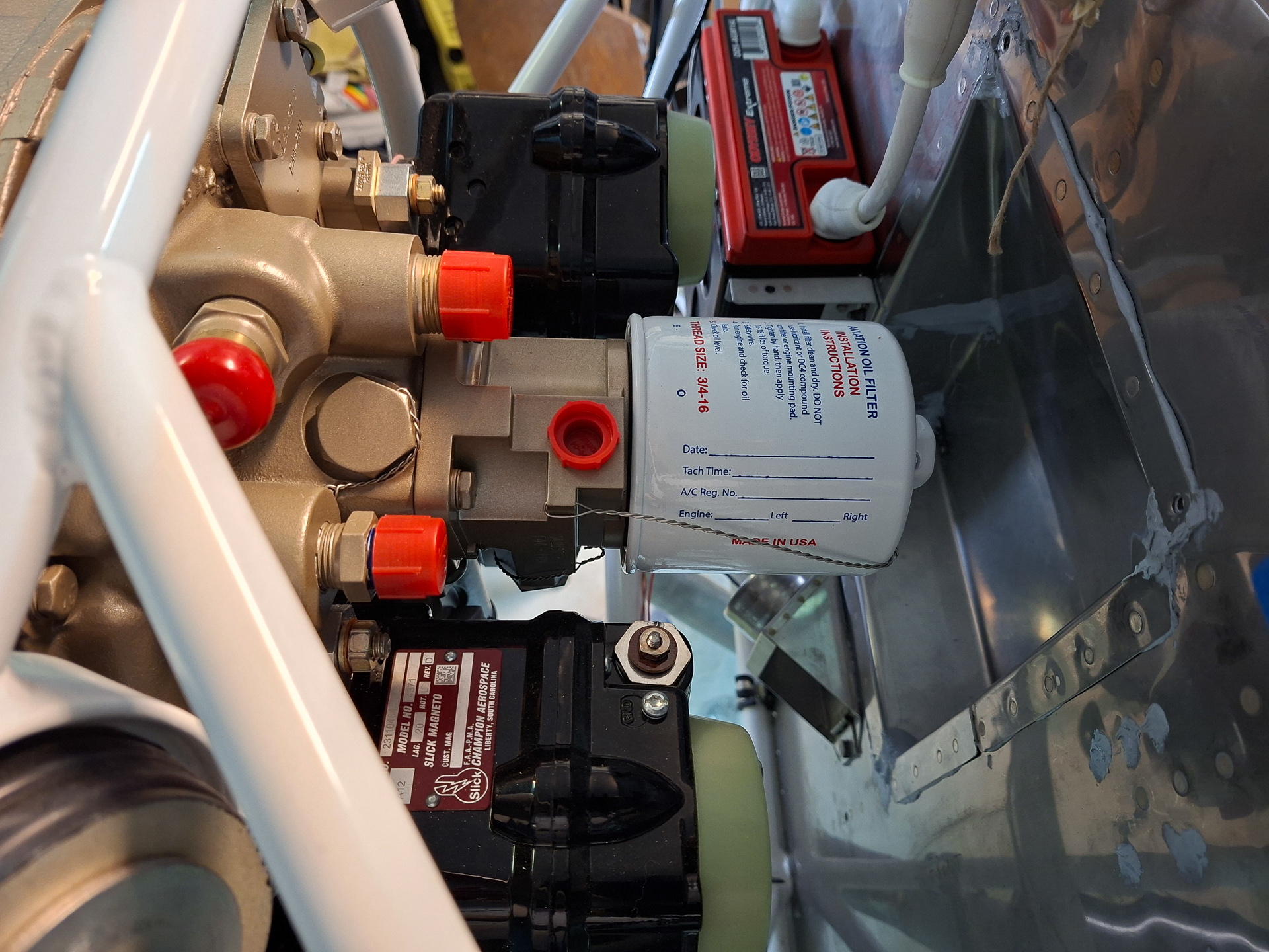
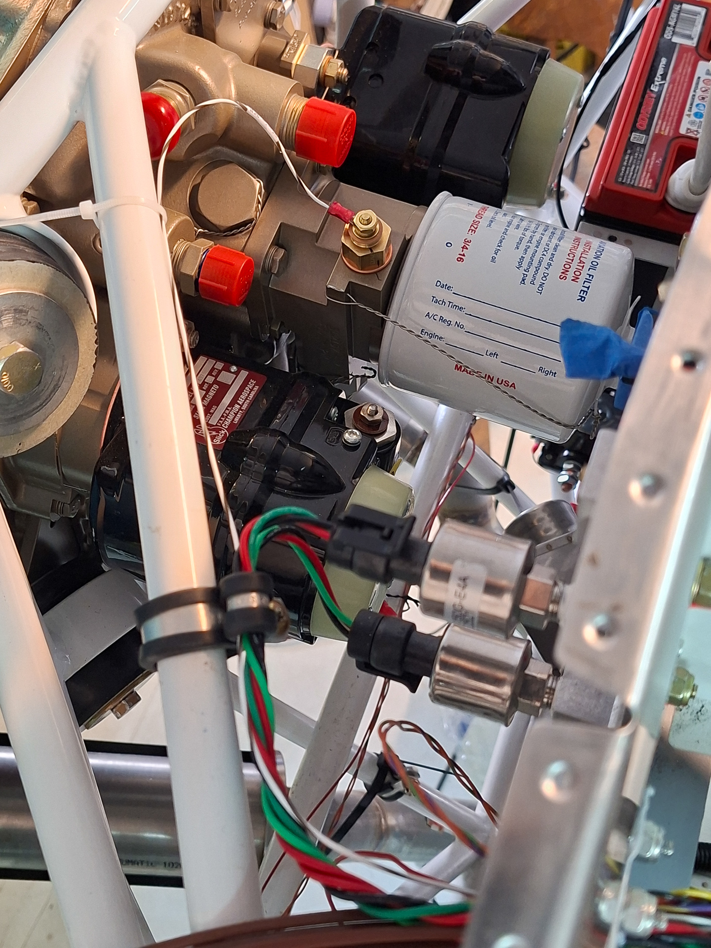
The oil temperature sender on a Superior IO360 is installed right next to the oil filter. It's the red cap immediatly to the left of the white oil filter.
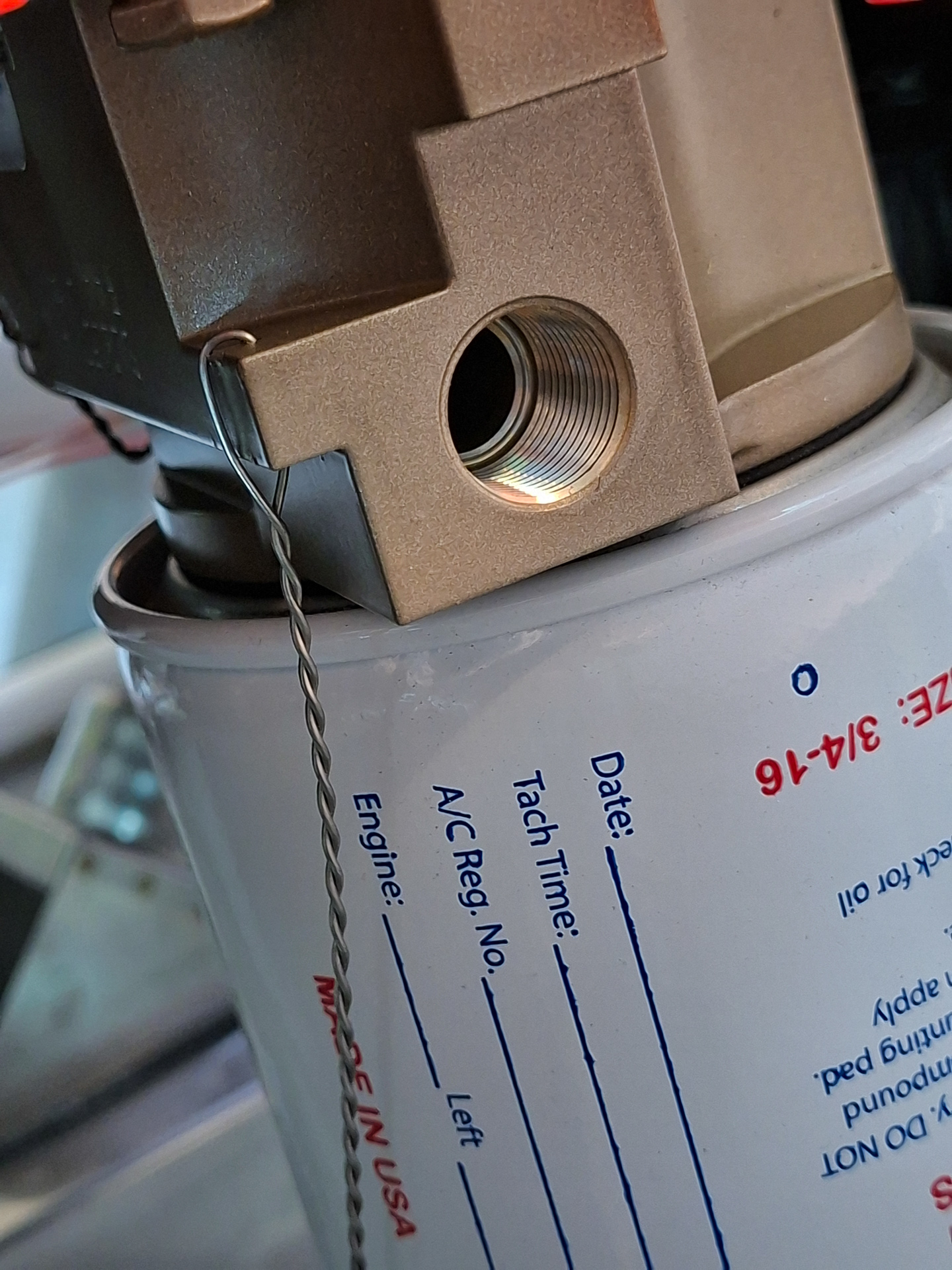
I removed the plastic protective cover and this is how the oil temperature pressure hole looks like. Make sure the sensors threads match the ones in the engine case.
I applied some nickel based loctite anti seize on the threads first.
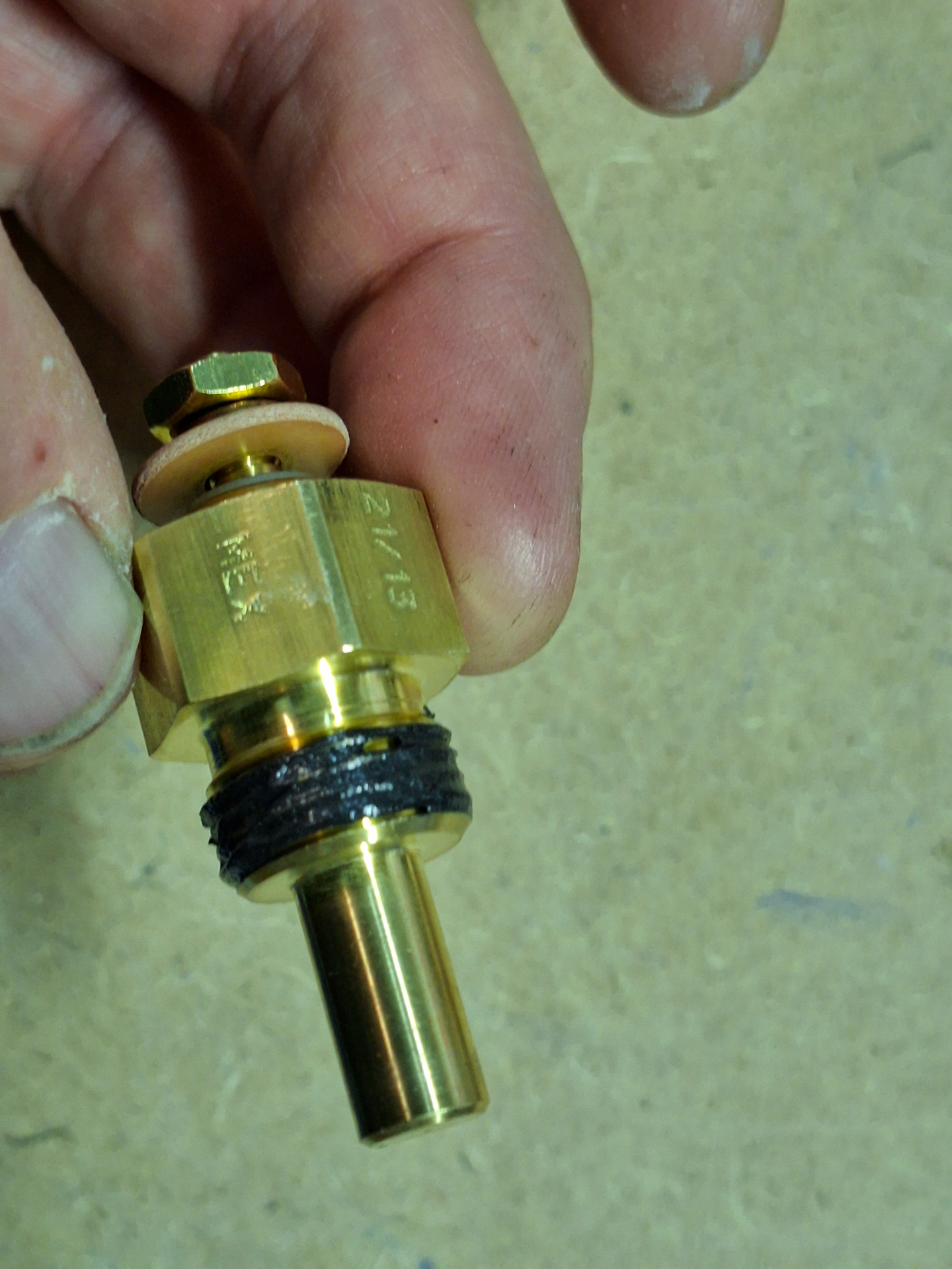
Then installed the sensor in the hole. A couple of things are important here. The sensor manual explicitly mentions that the copper washer should be nicely centered on the sensor body. If not, oil leaks may be the results and we definitly don't want that. Also pay attention to the orientation of the washer. Smooth side on top,rough side (seam) on engine case.
You tighen this pressure by hand until it's hand tight. Then you verify the setting in your engine manual how to torque or fasten this.
In my case, appendix C "table of limits" of the superior install manual mentions this:
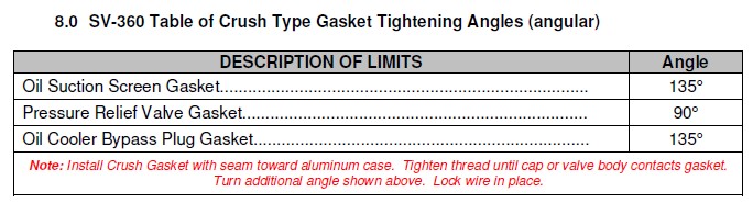
Turn the sensor to an angle of 135° from the finger tight starting point.
I made a mark on the sensor and the engine case at finger tight (see top marks) and then marked the 135° location where the sensor should end up.
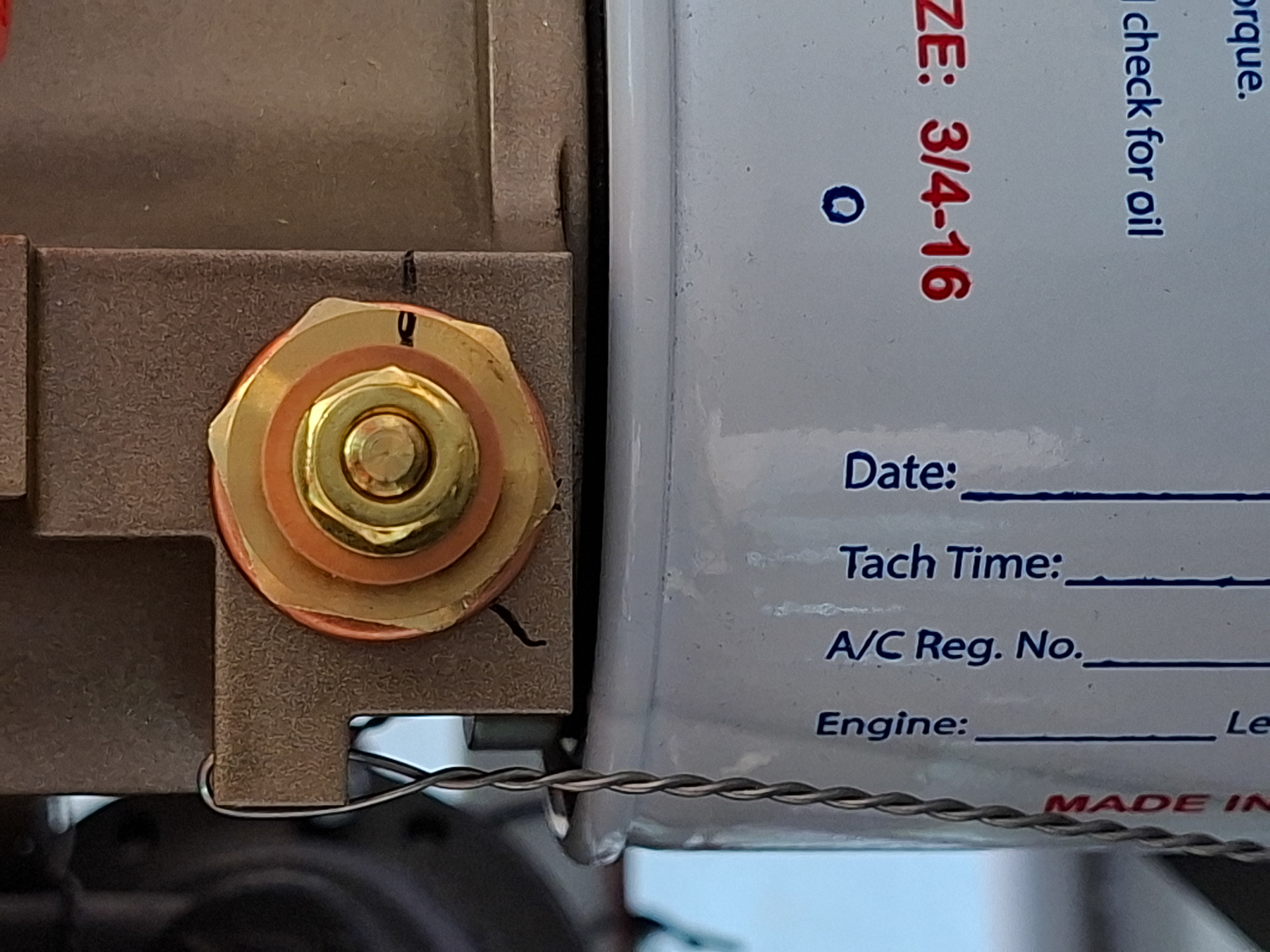
The next image has the sensor fastened on 135°. Look very carefully that the washer remains nicely in the center of the sensor and look at the hex points on the sensor in relation to the copper seal gasket. As you see in my example the washer is nicely centered.
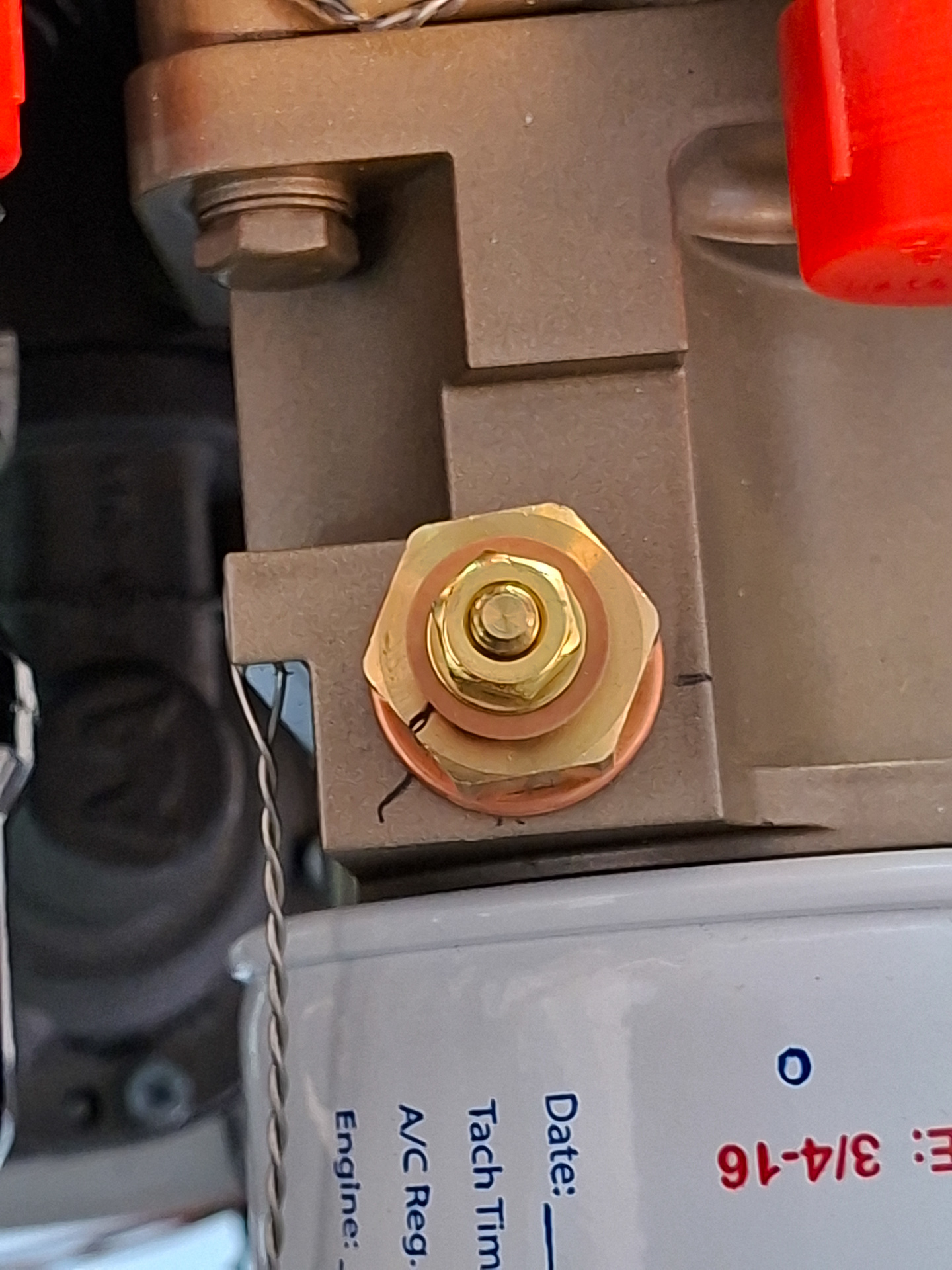
Next I ran the EMS sensor wire for temperature measuring (pin 7 white/brown) to the sensor. The sensor itself is grounded by the engine case.
Guided the wire over the engine mount bar and bring it together with the other sensor wiring.
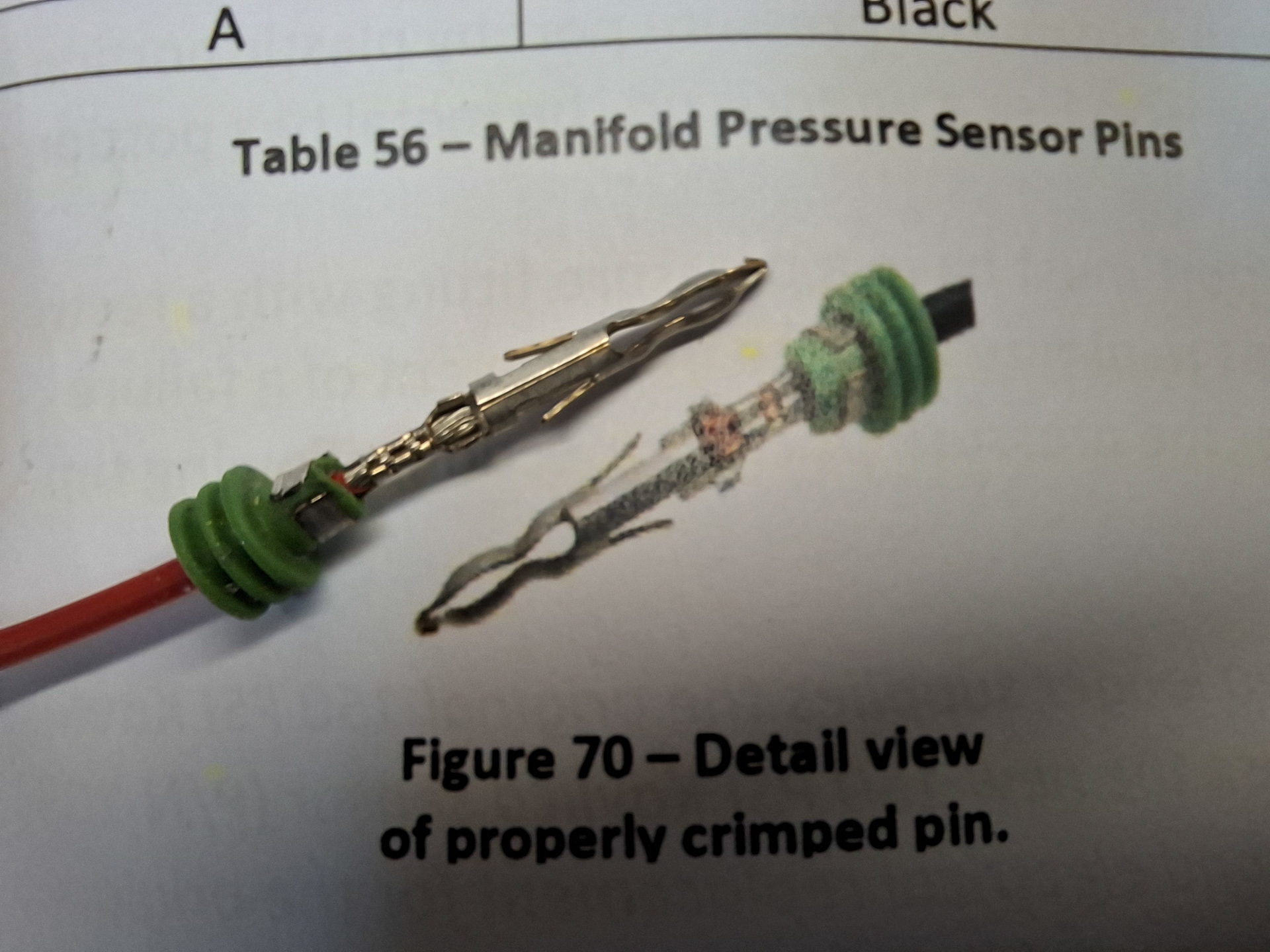
As I had some time left, I also connected the Dynon MAP sensor wiring to the firewall unit. Then manual shows how this weather proof connector should be crimped. My pin it next to it.
Then ran the 3 wires back through the firewall. There is one common 5V power wire shared with the other sensors through the EMS bus bar and one common ground wire.
The actual sensor sense wire is pin 26 on the EMS sensor (green/red)
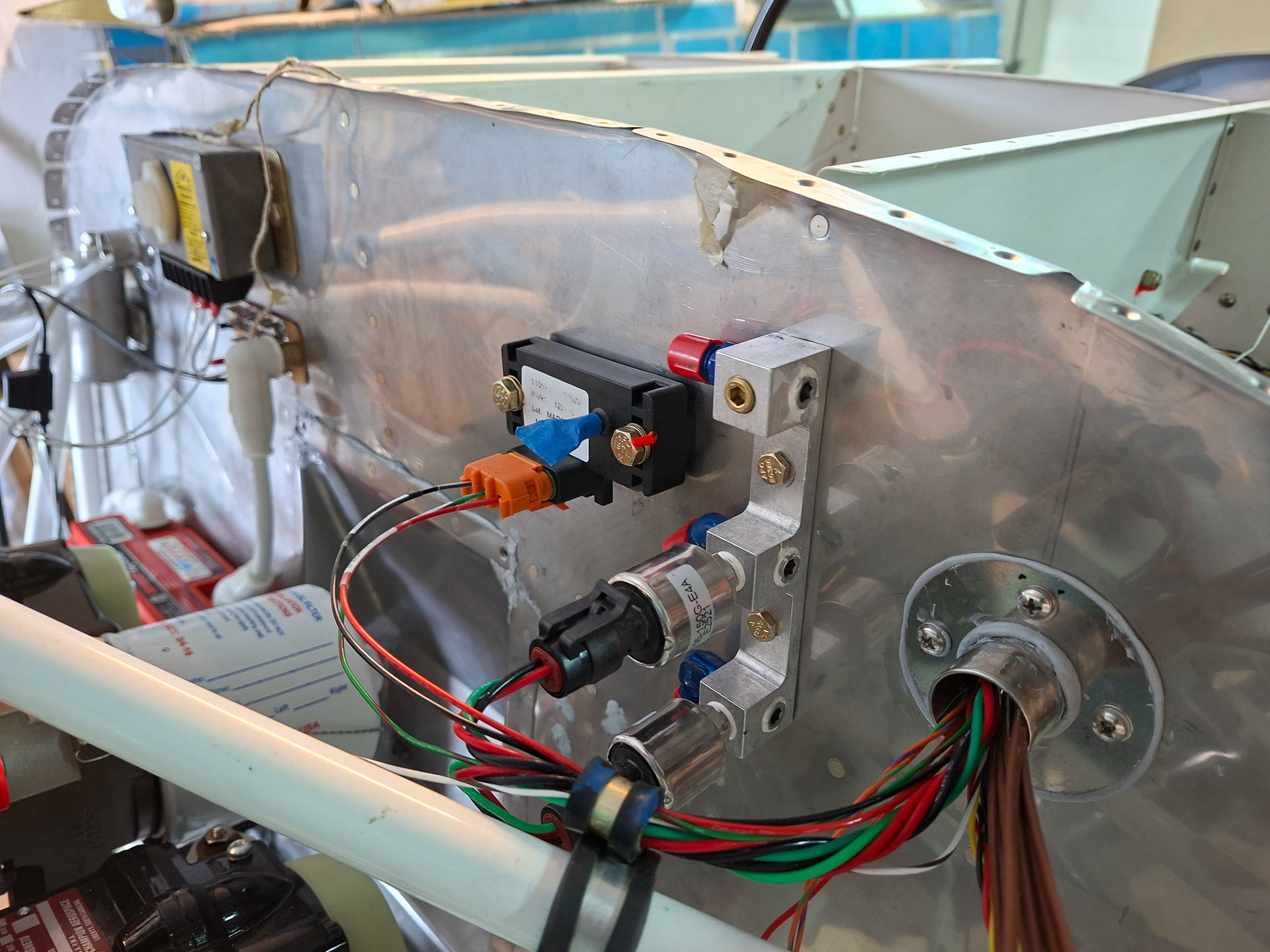
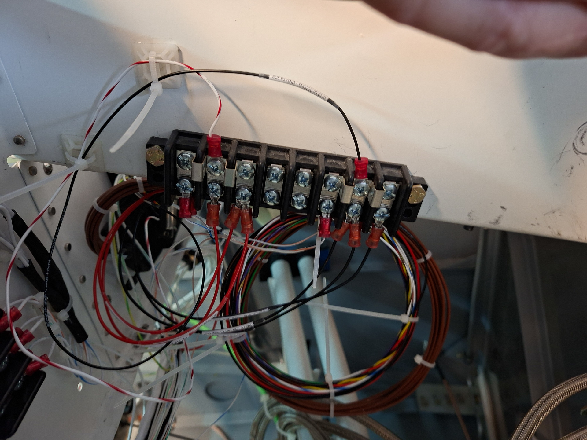
the EMS bus bar is shown below. It's actually used as a distribution block splitting of pin 17 (ground) and pin 18 +5V from the EMS module.
The sensor all share this connection as well as the roll and elevator trim motors.