In the long wait time for the engine to arrive and the electrical work coming to an end, I'm looking for more electrics things that I can already do in anticipation of the engine arrival.
I did already install the master and starter solenoids and one of the remaining things I found that I could already start working on is the starter switch.
I have classic slick magneto's with impulse coupling. An interesting article on magneto's can be found in the kitplane magazine in this link: click here
It talks about the importance of correct wiring of the starter switch in case of impulse coupling magneto's.
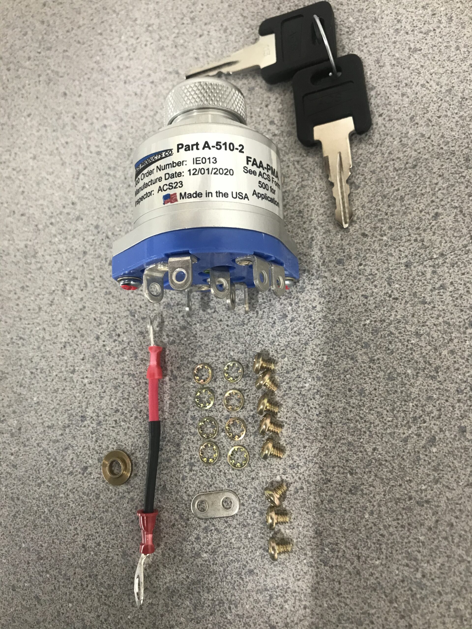
I purchased the ACS Model A-510-2K which includes a starter crank switch position. This is how it looks like.
The starter switch get's power from the VPX and ground out to the ground block. One wire goes to the S terminal on the starter solenoid to engage power to the start solenoid and engage the engine starter while in the crank position. The way this works is that a low power is sent to the starter solenoid which closes the contact and provides starting power over the big posts/terminals to allow battery power to feed the starter enginge. That's what the S terminal does.
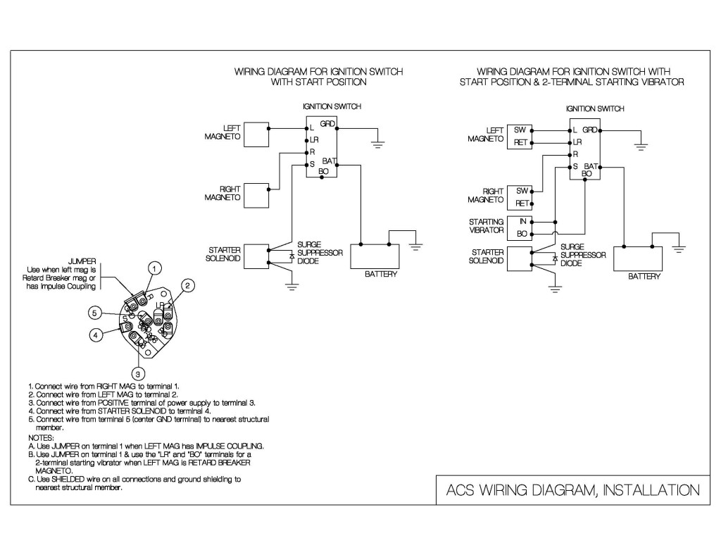
The starter switch comes with this manual and wiring diagram. For now, I'm just going to focus on the starter ignition wiring. The starter switch will also connect to the P-leads of the magneto's to ground them out when in the off position or when in one of the R or L positions. There is an important remark in the kitplanes article above when using impulse coupling.
In normal operation mode, both magneto's fire at 20-25° before top dead center of the cylinger head. This makes starting the engine more difficult. Therefor, the Left magneto is an impulse coupling magneto. What this does is that in low starting speeds and in the starter position of the switch, the Left magneto fires at 0 degrees top dead center. In cranking position, the switch is only firing on the Left magneto and the Right magneto is off (grounded out) This is crucial and needs to be tested upfront as this could be disastrous for your engine and lead to kickback on the engine if both magneto's would be on and firing at different degrees from top dead center.
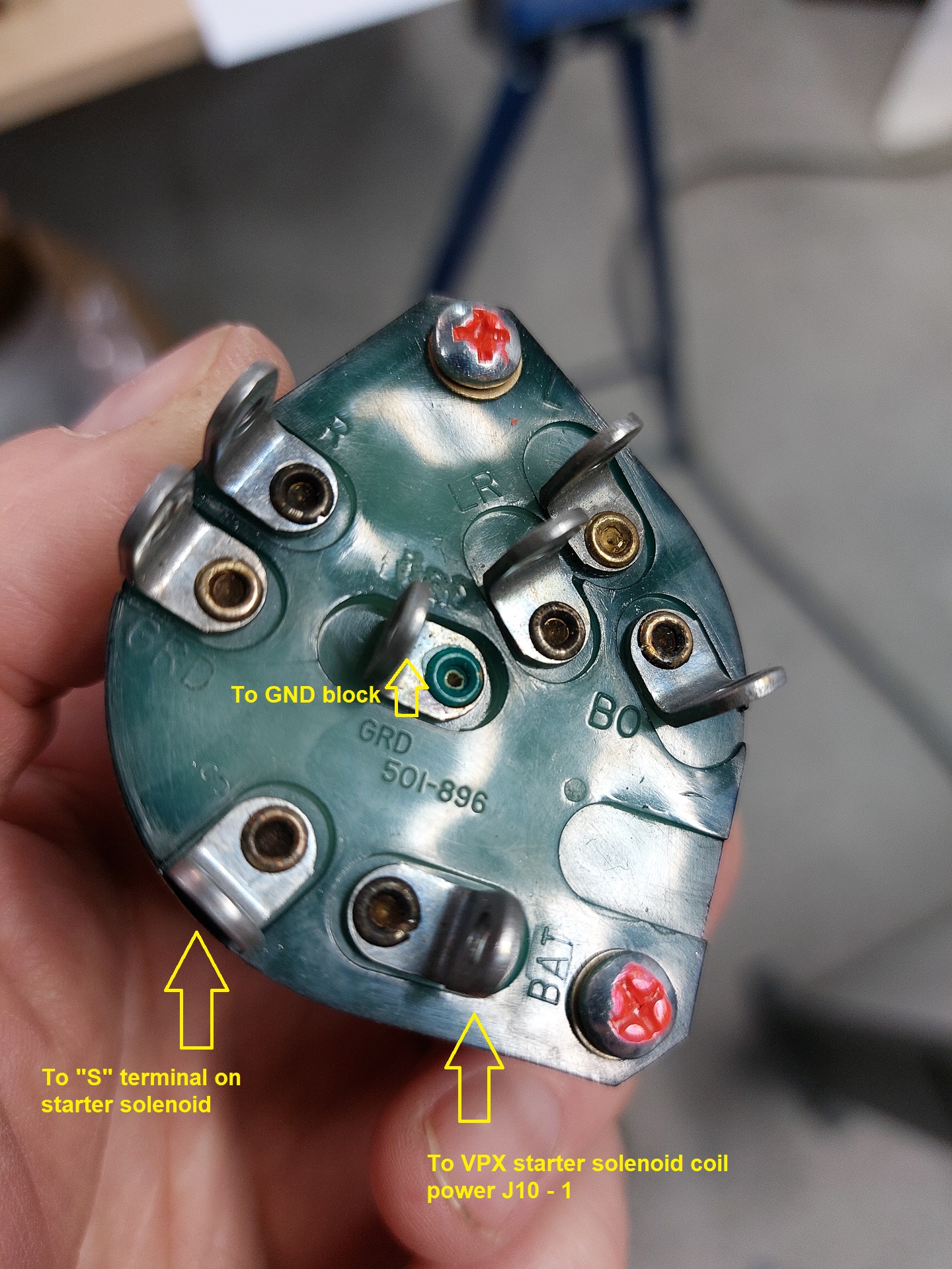
Here is a shot from the back of my ignition switch. You can see the different prints on the electronic board for the different connections. S obviously goes to the starter solenoid S terminal, GND connects to the ground block on the firewall and the power tab "BAT" connects to VPX starter contactor coil power circuit J10-1. Don't forget the Diode on the starter solenoid which you should have installed when installing the starter solenoid. You can find this info as well on VPX installation manual page 28.
ACS has put out a service bulletin SB92-01 for inspection and lubrication of ignition switches.Ignition switches manufactured after 1989 have red lacker over the screws. If your switch was operated once without a starter solenoide diode installed, you still need to do the service bulletin and have already been lubricated. If you have the red paint and didn't operate without diode and the diode is installed, there is nothing to do. They don't need to be reinspected until at 2000 hours of operation which surely is a long time away from now.
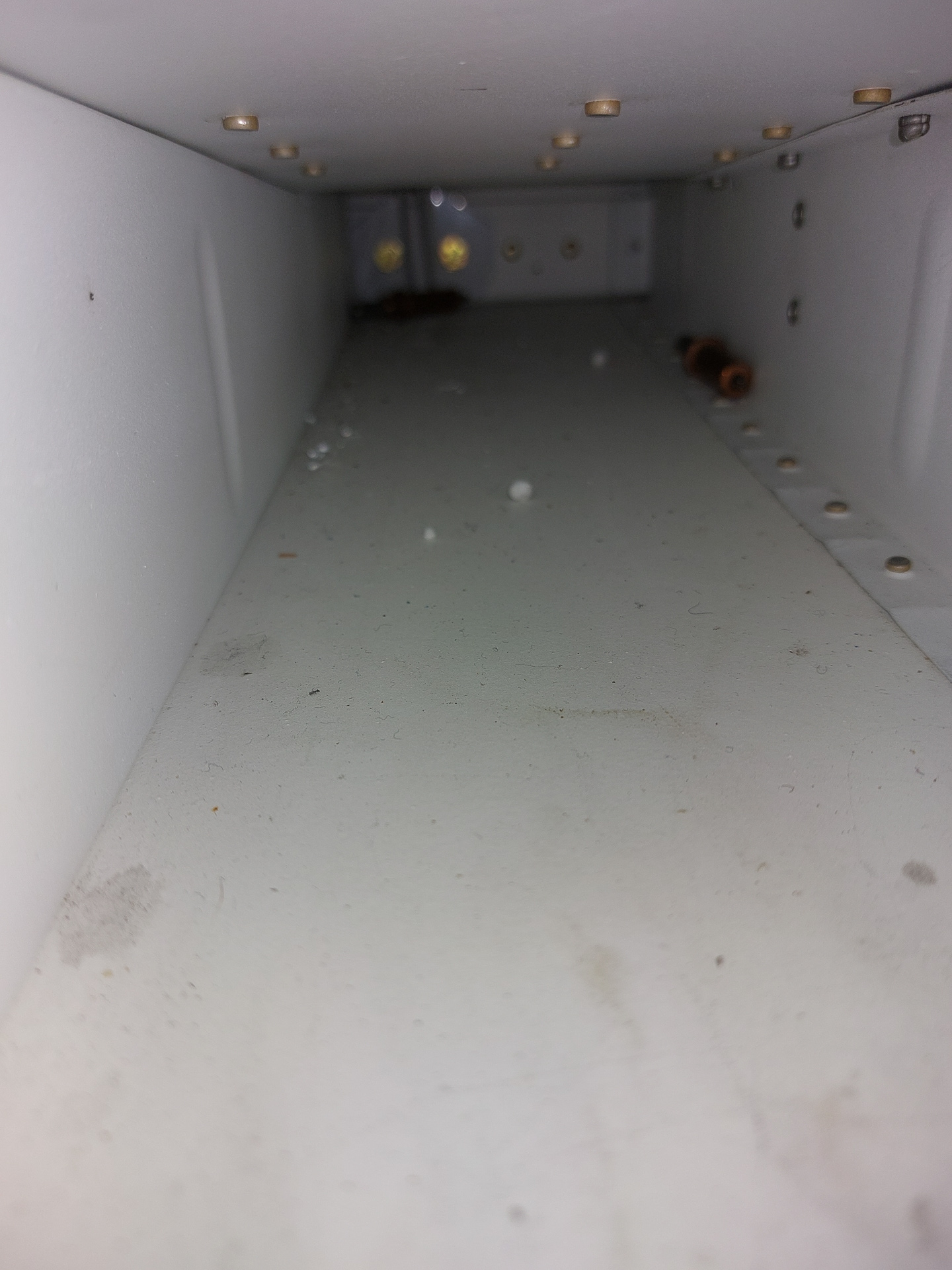
Was also cleaning up a bit under the seat covers and found some lost items... It proofs once more how important it is to keep track of things while working. Found a cleco underneath the seat covers. Keeping things clean is a good practice.
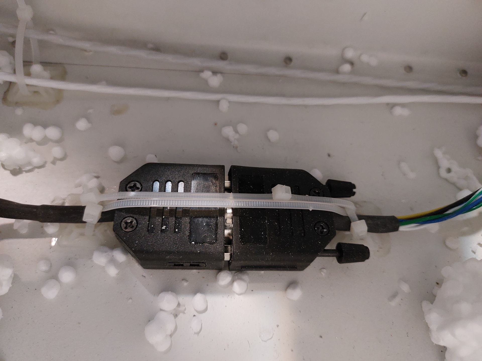
Next I did some tie wrapping of the connectors of the AP Dynon pitcho servo.


