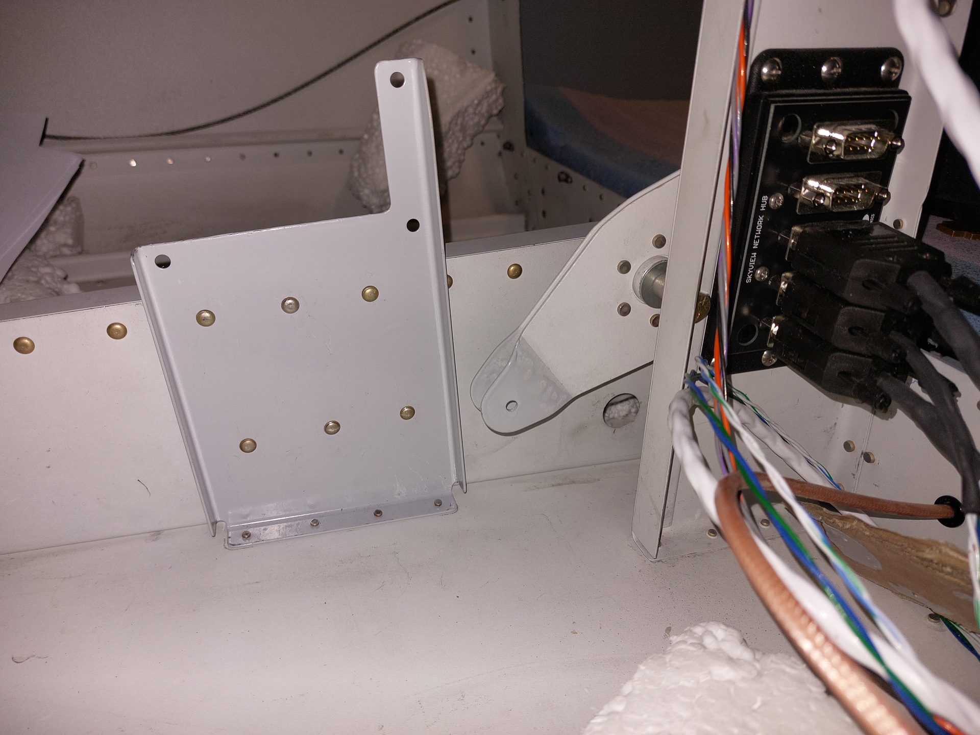
Waiting for the engine, I'm looking for addiontal tasks to be completed. The lack of a more detailed manual or track after the finishing kit is completed makes planning remaining tasks more difficult. As I'm working on electrical parts, I decided to tackle the Dynon autopilot servo installation. I remembered I had purchased the install kit with mount bracket for both the roll and pitch servo's. The roll servo bracket was installed when I assembled the aileron pushrodes and installed the hinge. The bracket on the pitch servo still had to be done and I had to dig deep in the dust to find the bag with the pitch servo hardware.
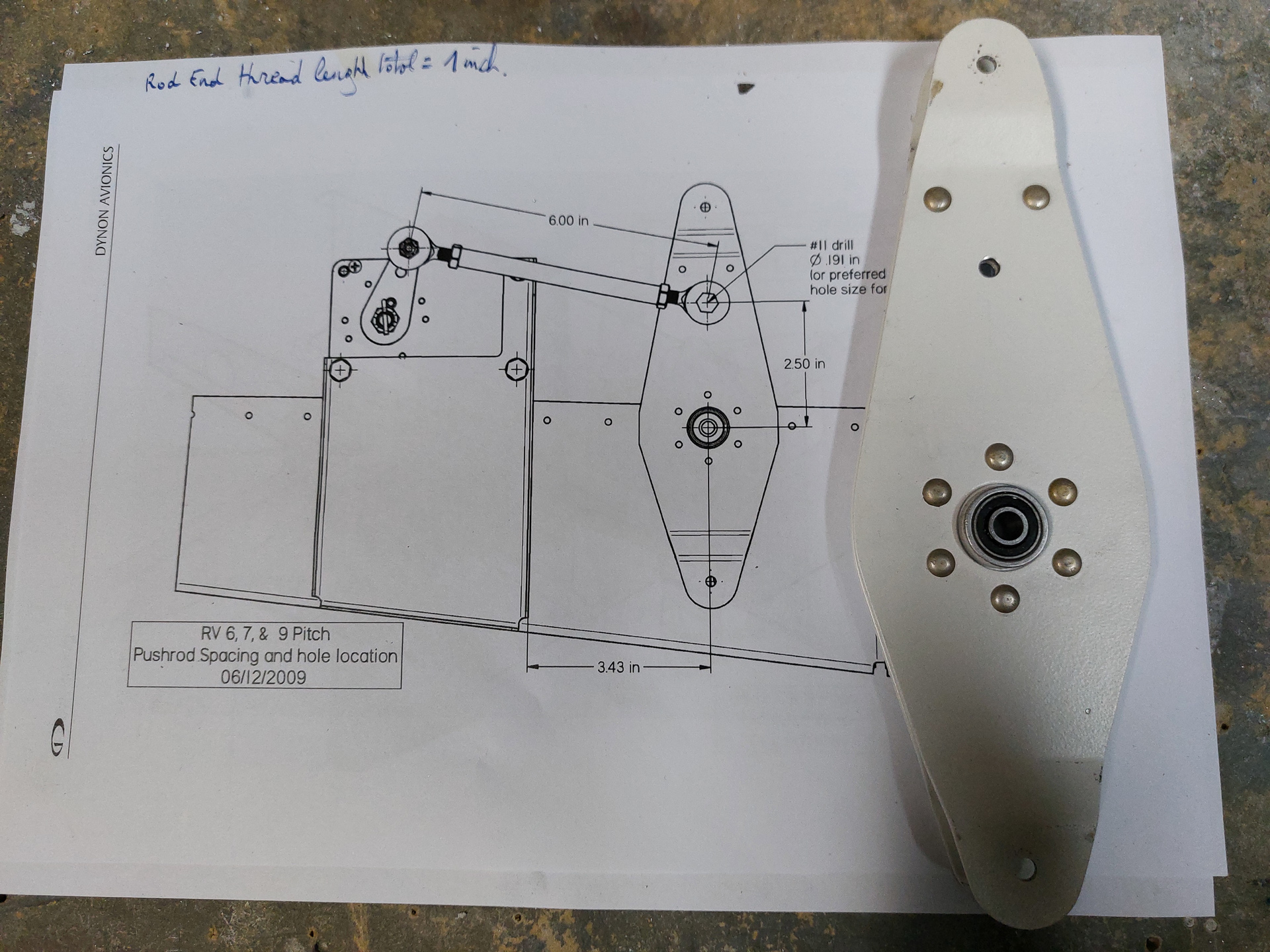
After reading through the manual delivered with the kit, I started with the elevator bellcrank (F-635). The dynon servo pushes a pushrod that moves this bellcrank back and forward. To allow for this connection, an additional hole has to be drilled in the elevator bellcrank. an AN3 bolt will hold the servo pushrod connection.
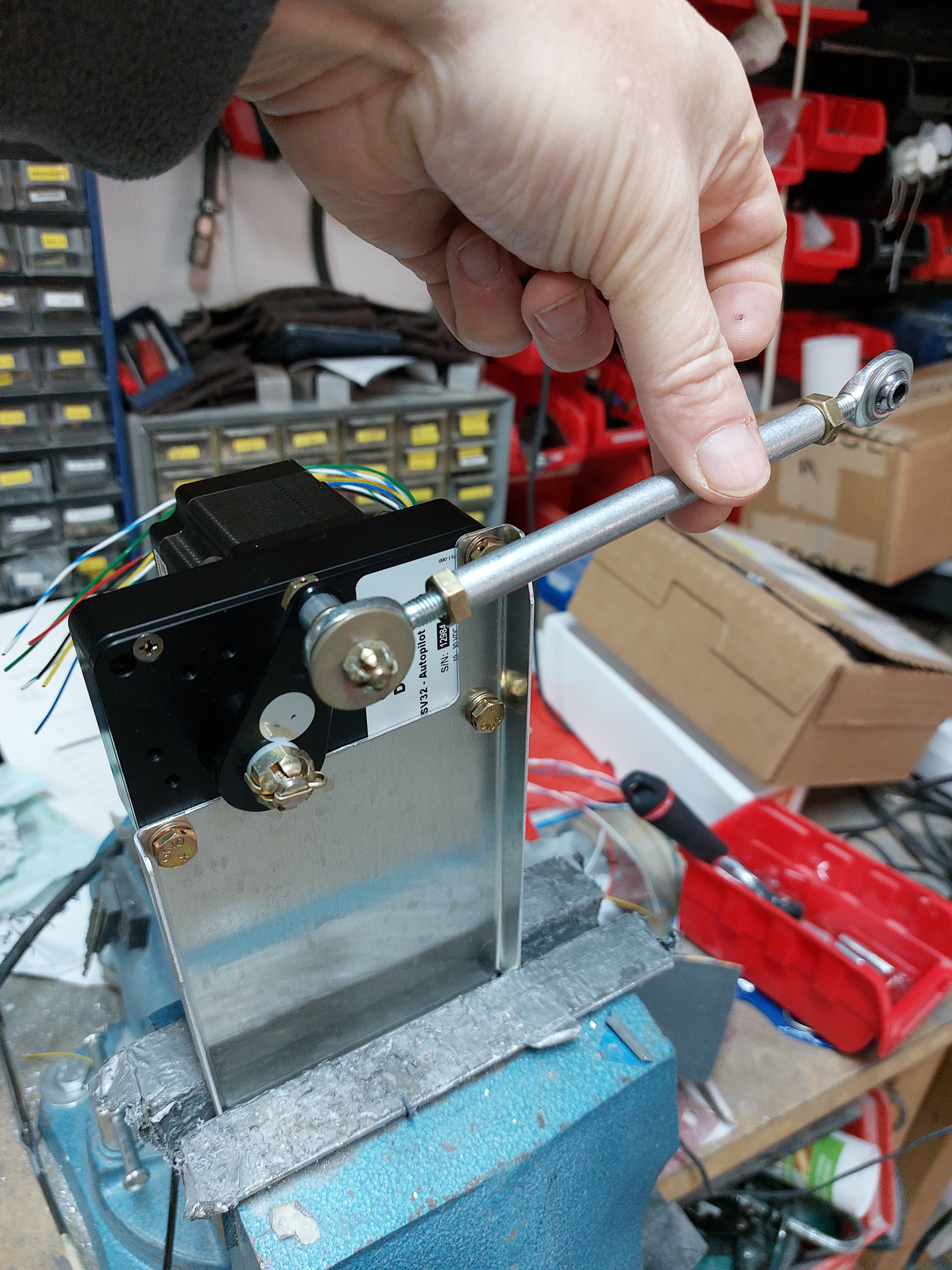
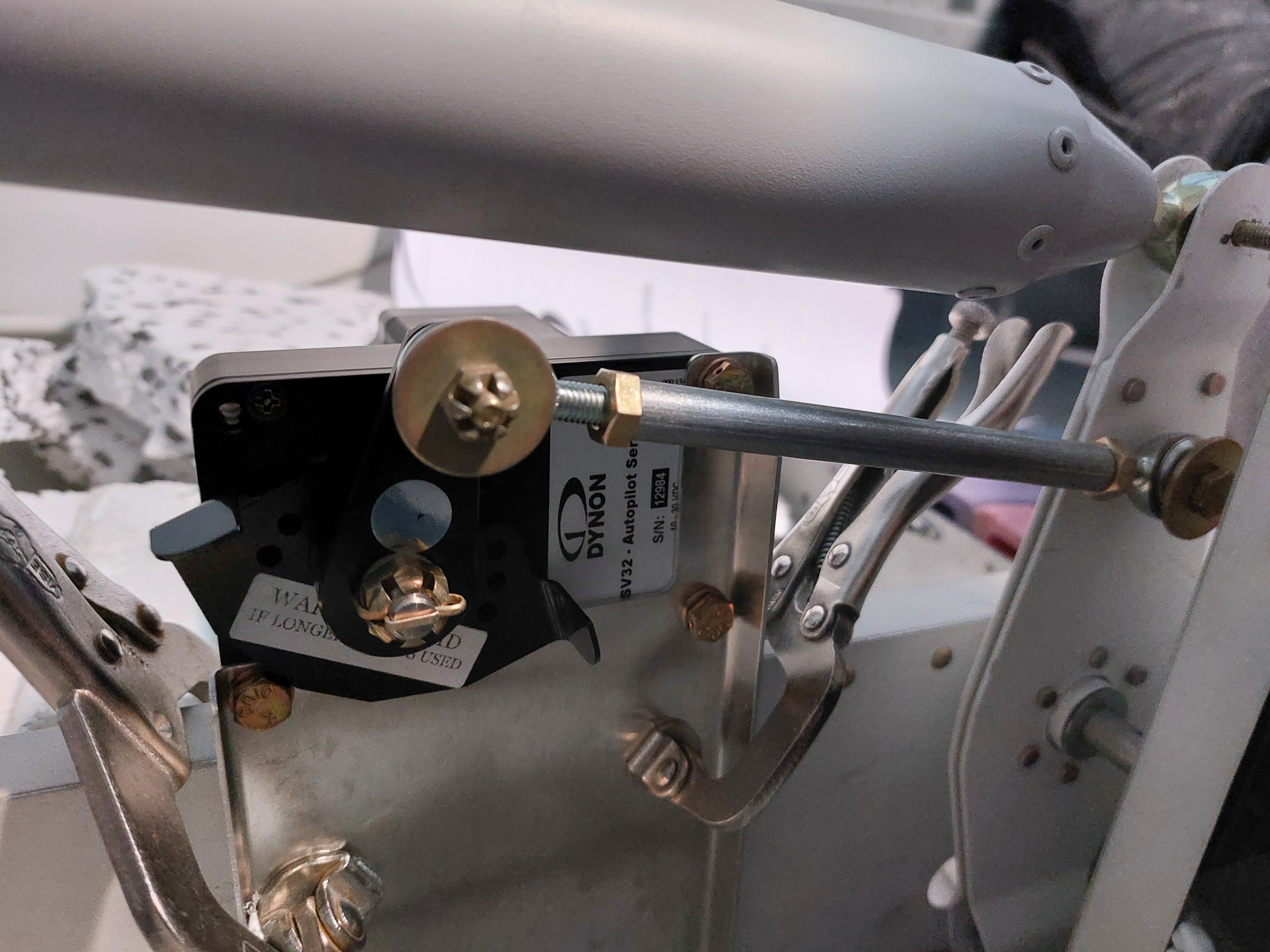
To have a better idea of how this is working, I temporarily installed the dynon servo on the bracket and installed the pushrod.
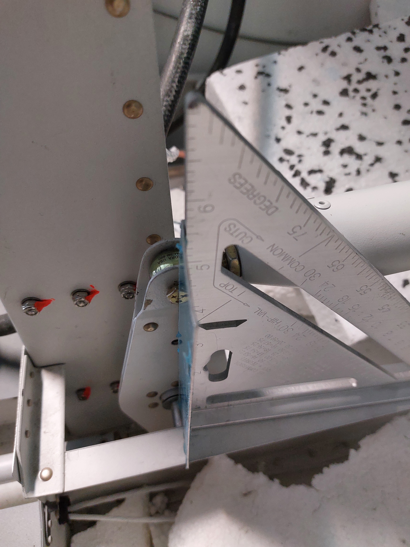
I wanted to get a better idea of distances and power required to move the servo arm. The manual stresses multiple times on controlling the over center position and I wanted to visualize this with the actual hardware. The length of the pushrod and distance fom the elevator bellcrank seem to result in the servo arm being slightly forward in the elevator bellcrank neutral position. The angle between the pushrod and the servo arm needs to be close to 90° in this neutral position to avoid over center locking in either forward or backward movements.
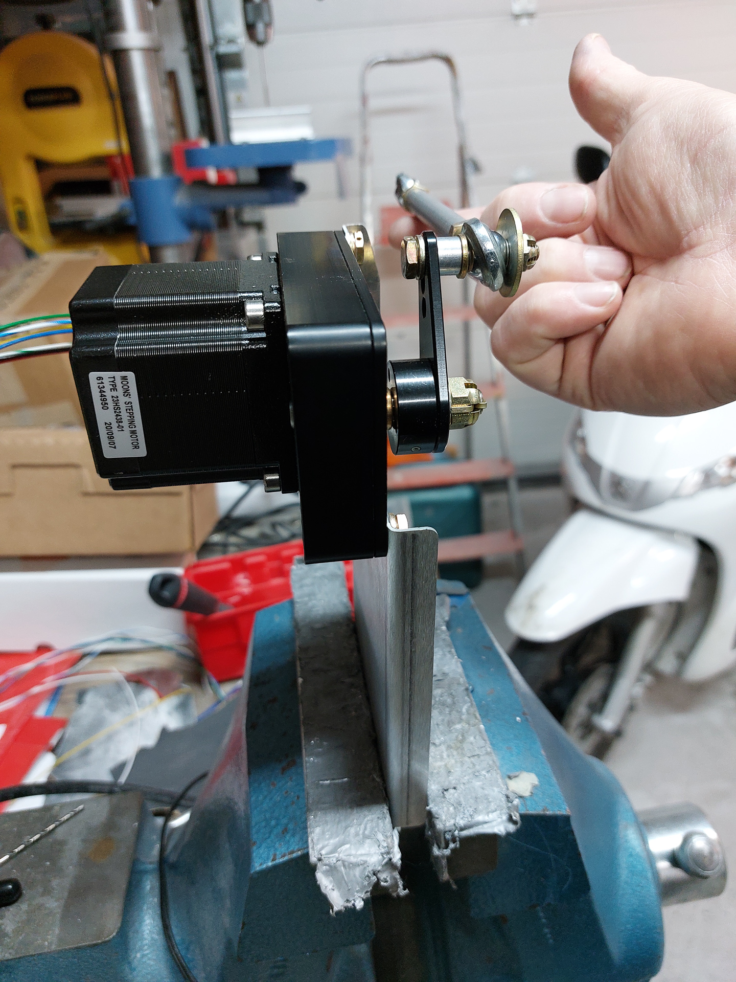
Rear view of the pushrod to servo arm assembly.
To determine the location of the elevator servo kit attach bracket. I needed to place the elevator bellcrank in the neutral position. This is achieved when the bellcrank is perpendicular to the F-729B bellcrank rib and angle.I placed a square on the aluminum angle on the bellcrank rib and verified that the new drilled hole was centered.
With the servo on the bracket and the pushrod attached, I moved the servo bracket back and forward until I got the desired spacing with the pushrod arm bearing screwed in at least half way in the pushord on both sides.
Clamped, removed the servo and drilled the holes. I added 3 extra holes on the bottom side for extra strength.
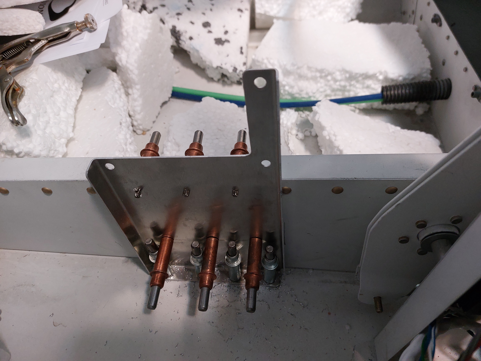
Primed the bracket, dimpled the bottom skin holes and then used the squeezer to install the AN470AD4 rivets. The AN426AD3 rivets in the bottom skin were shot with the gun.