
With the suntail tested and working, I thought it was a good idea to continue the wiring of the wing tip lights. My plan is to bring the plane out, attach the wings and have everything lighted up.
Installed the molex connectors for the Aeroson Pulsor NSP lights first. This will allow for easy removal of the wingtip or replacement of the NAV light if ever needed.
Then ran the multiconductor wires for navigation lights and taxi/landing lights through the conduit. The multiconductor wire is shielded and the GND wire is connected all the way through across the shield.
You don't want the GND wire attached to the outer rib locally as this may increase the risk of ground loops that will cause electromagnetic interference on the radio's.
I had to do some research and get help from fellow builders as I'm not a big hero in electrical work. The best way to do this is to connect the GND wire on the shield and have the shield on the cockpit side connect to the GND block. To achieve the connection of the GND wire to the shield, steinair sells solder sleeve. These our heat shrinkable plastic tubes with low temperature solder inside which can melt the solder inside by heating with a heatgun. Some glue at front and end of the solder sleeve ensure a thight fit of the sleeve
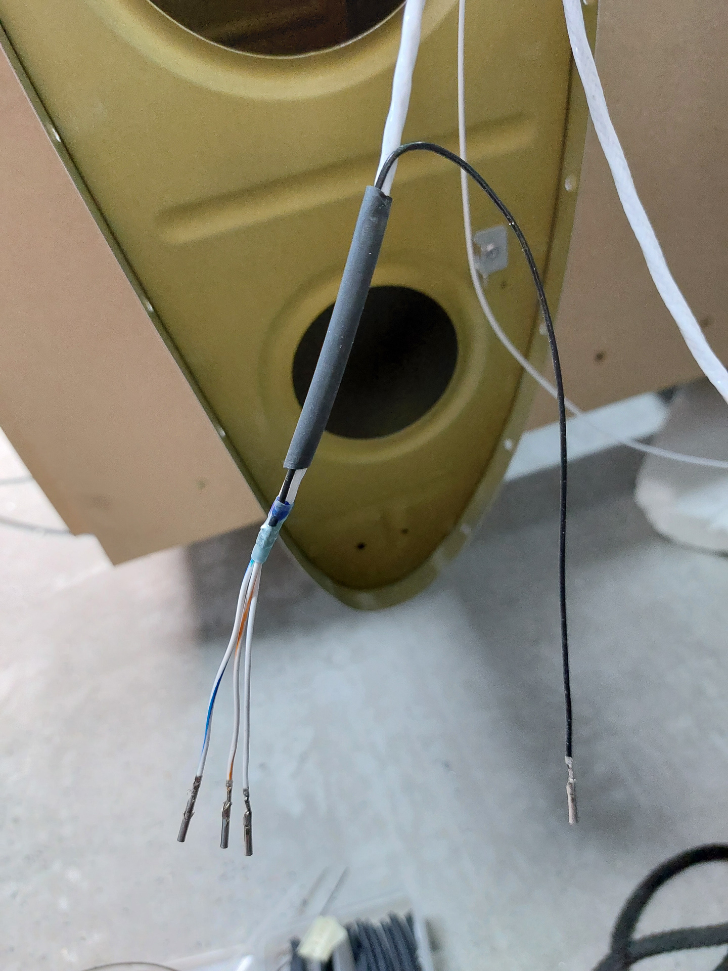
In the image below, you can see the solder sleeve installed on the wire (just below the block heat shrink).
To install such a sleeve, you expose a part of the shield by cutting back the insulation. put the heat shrink over the wire with the solder ring over the expose shield. The blue glue goes on the remaining insulation side. Then you slide the black gnd wire underneath the solder sleeve at the same position as the shield and apply the heat from the gun. Heat evenly so that the solder melts equally.The wire is attached from the back which forms a more solid connection once some additional heat shrink is place over the assembly. The image below shows direction of the black GND wire. It will be folded back with the other wires and attach to the connector.
The only local grounding I have it for the lightning protection of the light case to the frame. That's the little tab you see on the image below near the front and top of the wing.
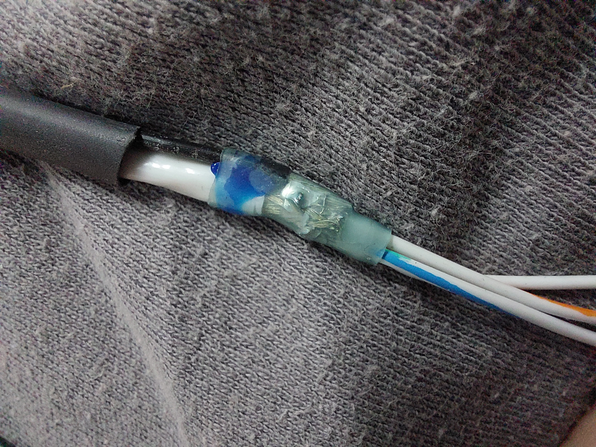
Close up image of the solder sleeve
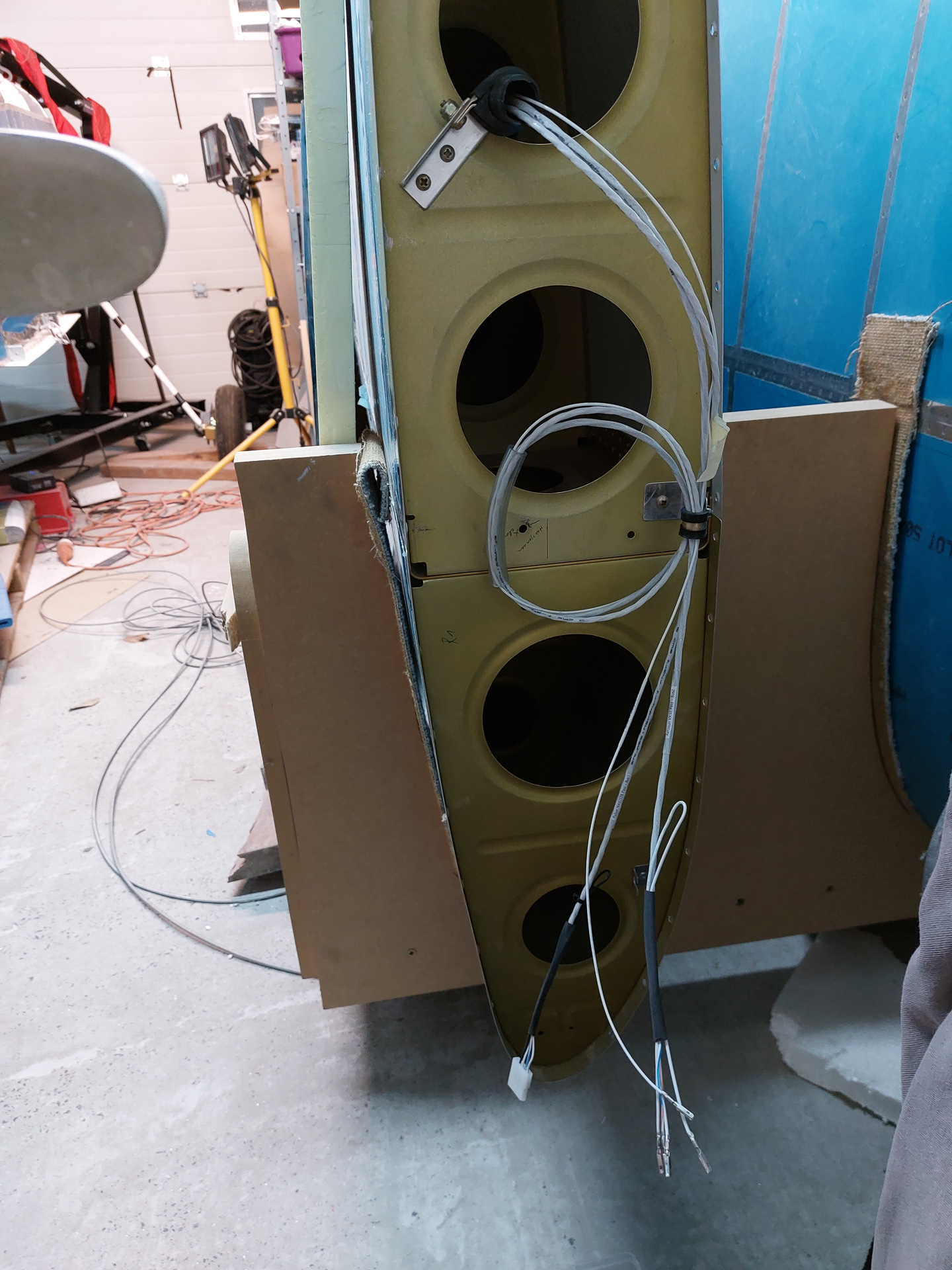
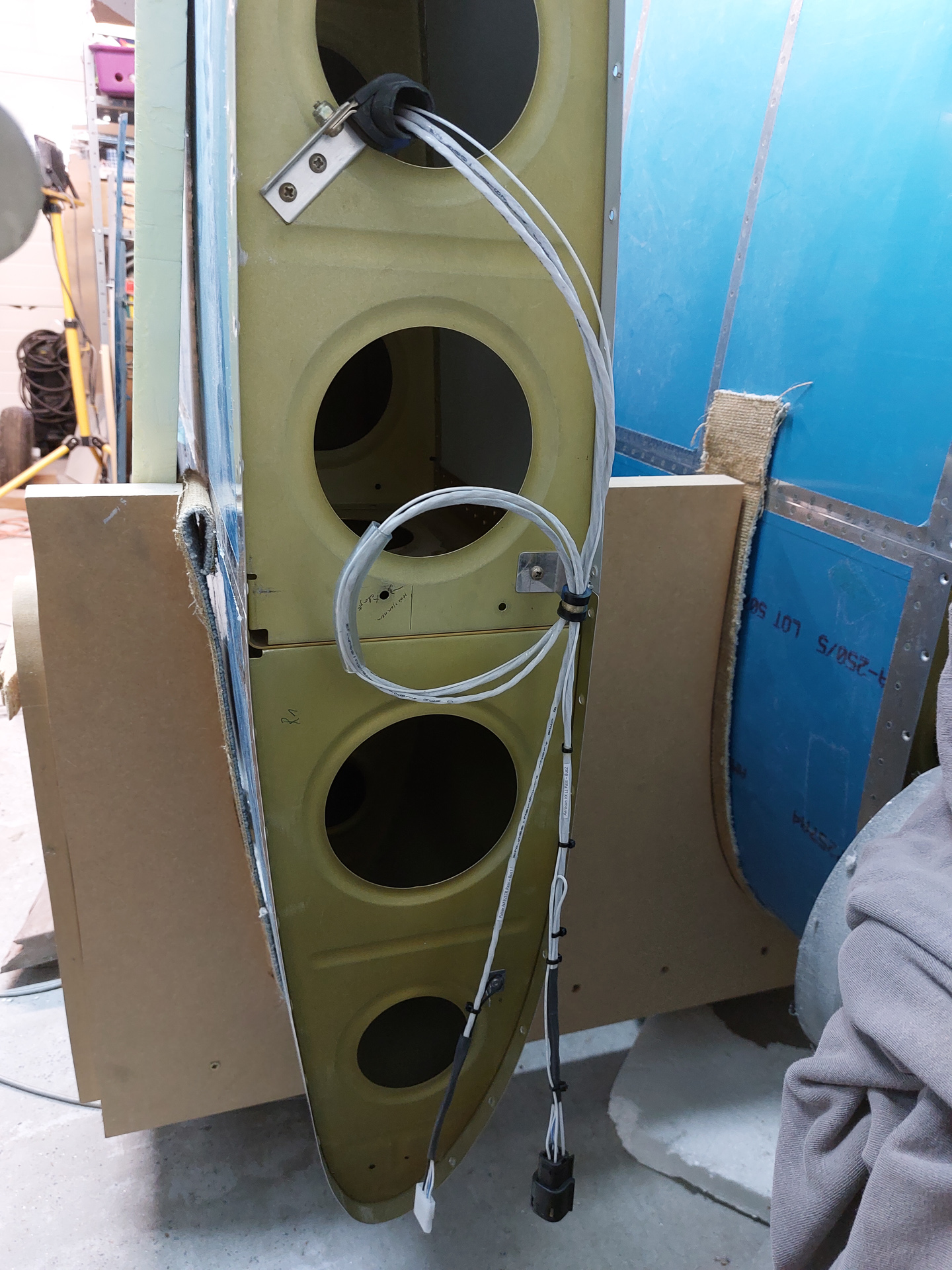
Both wires done. I kept a service loop for both wired. The individual wire added on top of the 2 multiconductor wires is the 20AWG sync-cable for the landing lights.
The sync cable for the landing lights does not run back to the panel area but is a straight connection between the two deutsch connectors in the wing roots. I believe the sync cable is used to synchronise the wig wag function of the Aerosun VX taxi/lights.
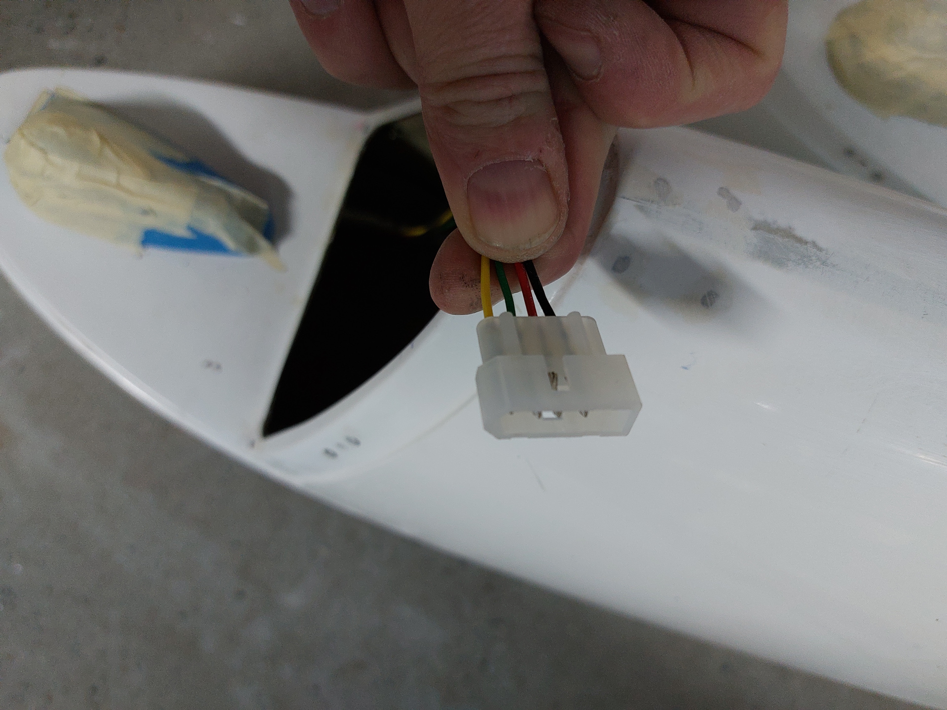
Pins are crimped and connectors installed. This one is ready for attaching the wingtip and testing the lights. The white connector is a standard 5 wire molex connector where only 4 positions are used. The black one is a more robust connector and also has molex style crimped pins. Both were delivered with the lights.
Repeated the same on the other wing.