With the engine delivery came a B&C starter and alternator. The alternator delivered is a 60Amps alternator of type LX60 experimental.
The LX60 comes with an external voltager regulator of type LR3D. The voltage regulator constantly monitors the voltage on the main bus (through a VPX pin) and activates the Field line into the alternator. It is the field that dictates how much current the alternator will produce to feed the bus and battery.
As it's an external device, this also means that it needs a location somewhere in the plane. Many debates have been held on the location of this regulator and you basically have 2 choices : either on the firewall FFW side or behind the firewall inside the cockpit sub-panel area. I talked about this with multiple people. I finally decided to hang it on the firewall FFW side. I want it away from the exhaust tubes where the temperature is not too high and my optionally duct some cooling air onto it. My mechanic who will perform my final inspection told me I should not worry about cooling the voltage regulator and that it is probably better to think about cooling the mechanical fuel pump to prevent vapor lock.
My initial thinking was to hang it next to the contactors, below the battery. But the location is not easily accessible in the lower cowl compartment and probably too close to my exhaust tubes.
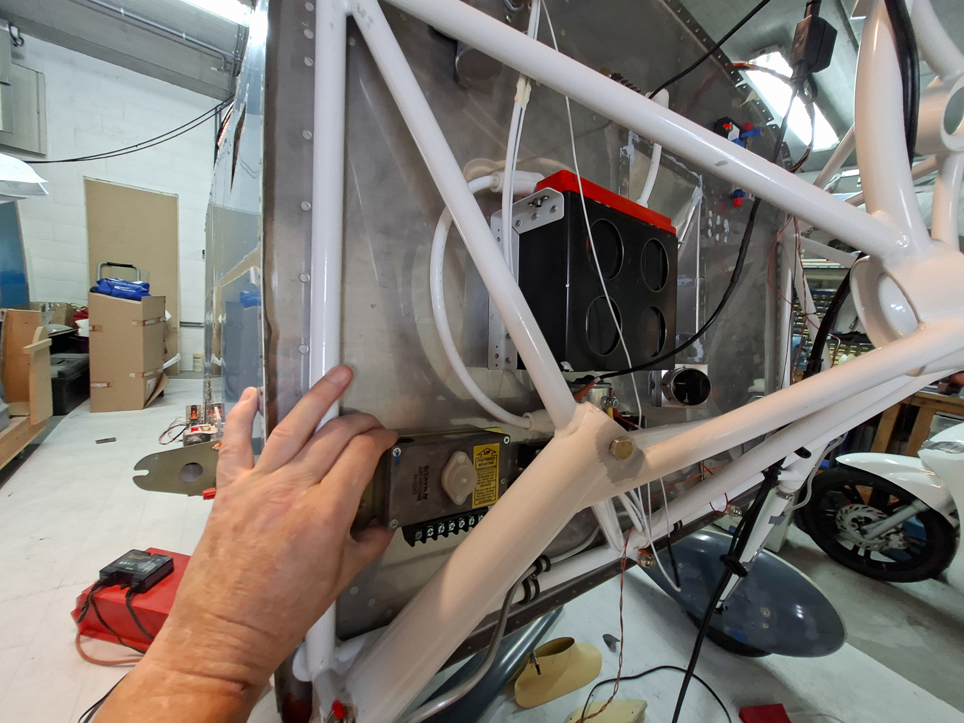
So the next option I see where it wouldn't bother other stuff would be near the top of the firewall above the ground tab block.
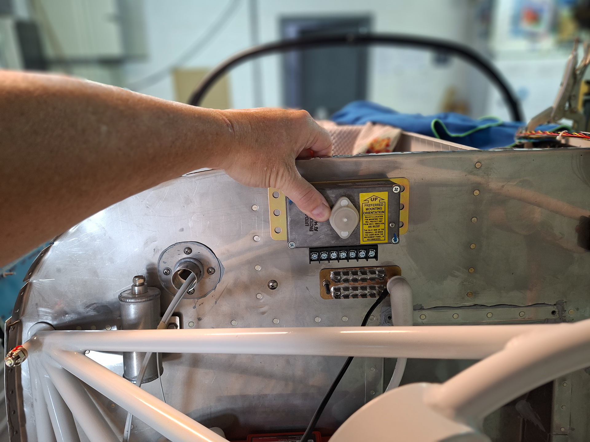
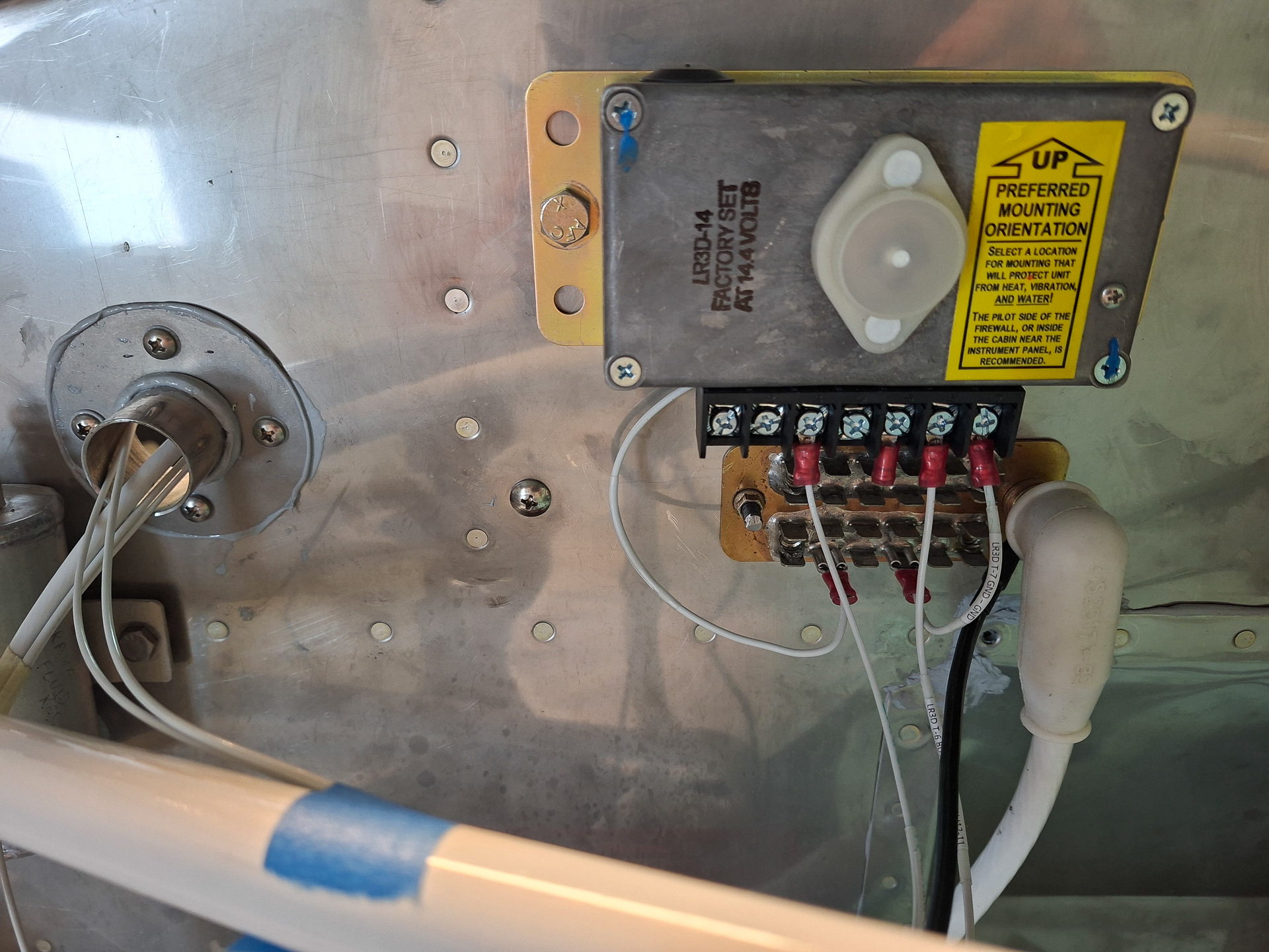
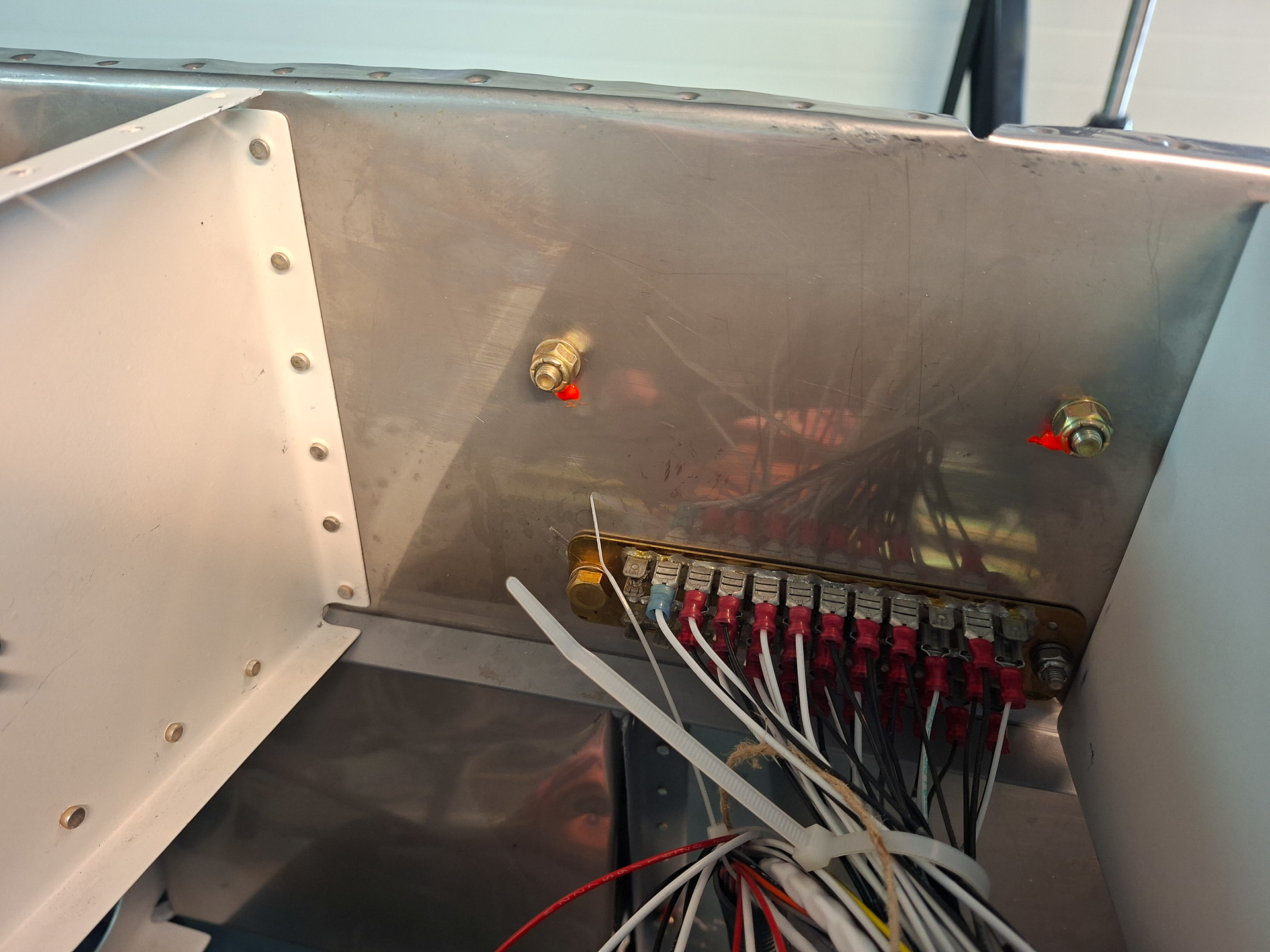
In the picture below, I drilled the holes and installed the bolts. The attach tabs for wiring on the regulator are far enough forward from the ground tabs so there is no interference.
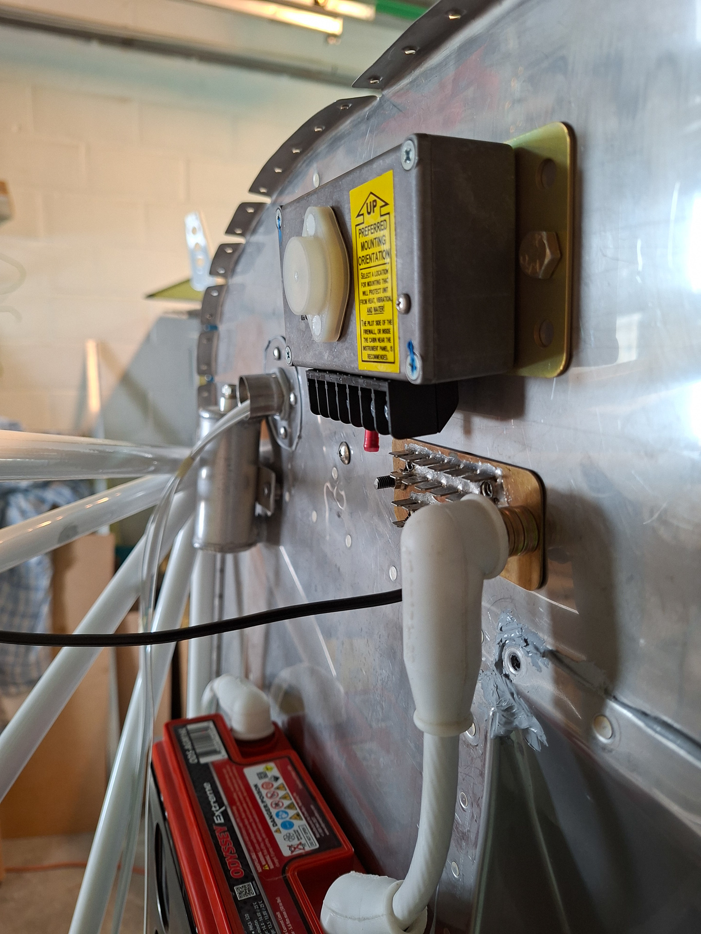
On the inside the bolts are high enough not to chafe anything and I torqued them to spec.
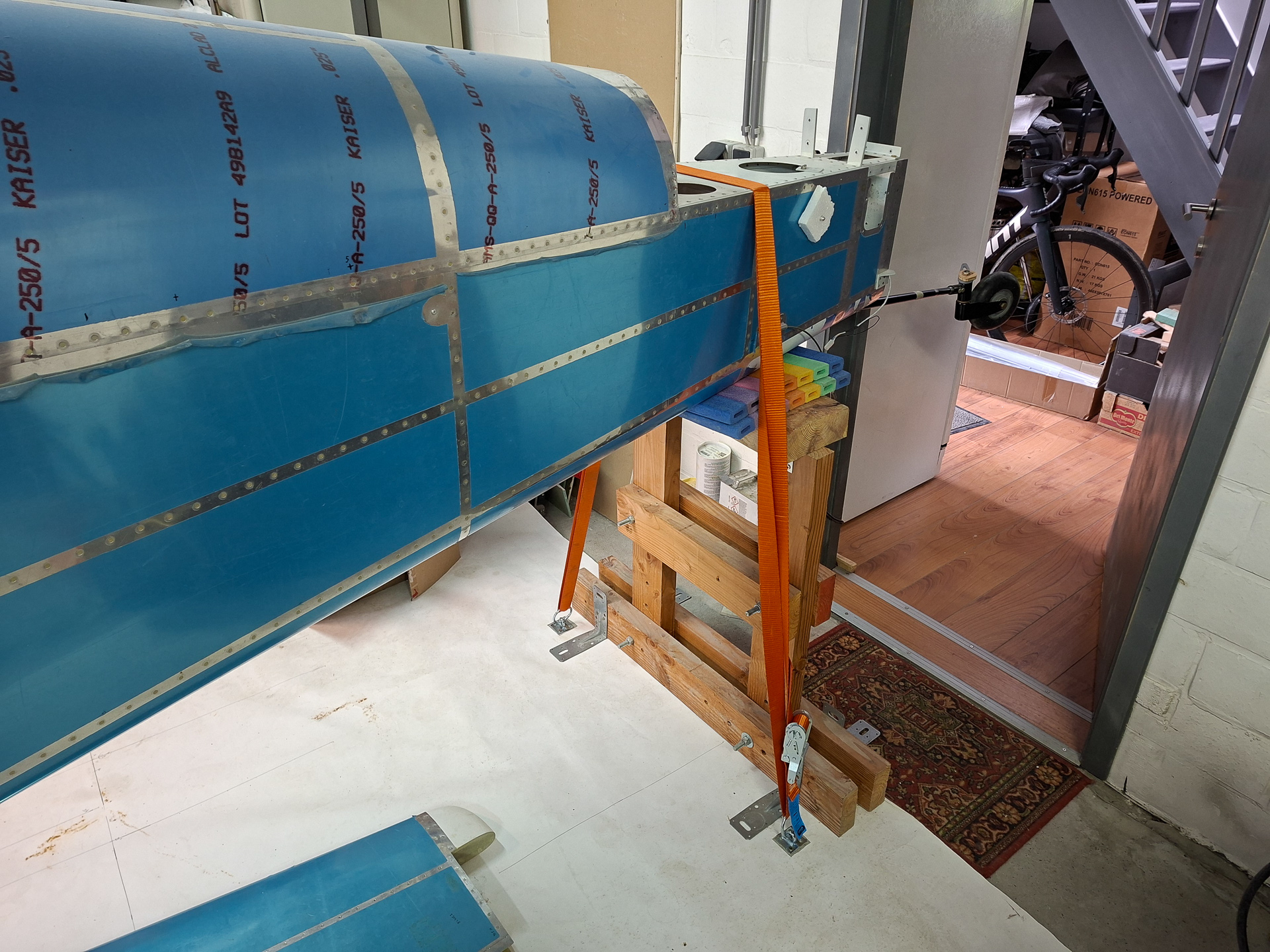
I am planning to hang then engine soon so I took some time to install hooks in the garage ground so that I can safely hold the back of the airplane down when the heavy weight is added to the nose.
Next I started wiring couple of wires on the regulator. Installed the 2 GND wires (one on pin 7 and one from the regulator case stud).
Then ran a wire from the ALT field pin on the VPX to the pin 6 "Bus Field Supply input" on the voltager regulator. On the VPX, this is a dedicated pin J12-11 with 5 Amp breaker. It is switched on when the "ALT field" switch is switched "on" on the panel.
The other wire is the Voltage Sense input wire at pin 3. This measures voltage on the main bus at the VPX input pin (in my case J12-8 protected by a 2 Amp breaker) .