2. Wing
The wing kit is the second major step in the build project. I started wing work 1st of September 2011 and finalised it end of December 2012.
Clicking the wing sub sections on the left side menu will only display articles related to that section.
Below is a list of all articles in the wing building process listed chronologically per subsection as I wrote them.
Arrival - 26/08/2011 - 7h
The wing kit and fuselage kit have arrived !
Today was like Christmas, received some presents from Santa. Only this Santa was wearing a high vis vest and large gloves to carry those heavy boxes out of the truck.
In total, there was 319kg delivered in three boxes. The heaviest on (containing the fuselage kit) is 140kg.
All boxes were in very good shape and hardly showed any form of bumps. The longest box containing the main spars and fuselage looked like it was packed in the factory just yesterday.
We opened the boxes and the picture below is how it looks like. The packing is really nice and stored in an efficient yet safe way. There are PILES of wrapping paper. Ask my neighbour Jacques how much fun it is to wrap them up again for disposal :)
The bottom crate is the fuselage kit, the back one is the main components for the wings and the long ones contain the long pieces like the adnodised wing spars and longerons.
Then the real work starts: making the inventory and unpacking all. Fortunately my buddy builder Fred came over to help me tick off items from the packing lists. The picture below show how you can do that in an efficient way :)
I have to admit that the amount of pieces you unwrap is a bit depressing on the moral, knowing you will be edge prepping every single one of them. On the other hand, can't wait to start building the wings now !!! go go go...
Main spar tank nutplates - 03/09/2011
I'm very excited that finally, I can move on to the next major subassembly of the plane: the wings !
Only very few things have to be done to the empenage (some rivets in hard to reach places) and I will do that when I have some better technique or better tools to do so.
The work on the wings start with preparation of the main wing spars. These are the most important parts of the entire plane and will take the most of stress and load so you better handle them with extreme care.
You will curse ! each time you drop something accidentaly on the spar (cleco, bolt,...) and create a small scratch. It will mean polishing it out later.
First you need to install the nutplates where the tank skin attaches to the main spar. The fuel tanks can actually be removed so all attach points of the tank are with screw. 8R8 screws (#19) are used to hold the tank skin to the spar.
This means you have to countersink the screw holes so that skin and screw sit flush when installed. Moreover, the nutplates that will hold the screw also need to be rivetted and countersunk to the spar. In other words: lot's of countersinking ahead!
There are about 30 nutplates per flange, 2 flanges per spar, 2 spars on the plane.
When starting the countersinking process, I discovered a serious problem on the main spar of the left wing. I still don't understand how I could have missed this during inspection when doing the inventory.The flange of the left wing on the inboard side is seriously bent in. I guess it must have been pushed by another part during shipping. However, the flange is thick and hard to move so it might also have been something that happened in the plant at Vans.
Because the main spar is so cricital and it creeps everybody out when a defect shows up, I decided to send a problem report to Vans asking for advice.
Their response was - as usual - a typical Vans support answer. But I'm happy I asked and to get confirmation that what I was about to do was the allowed and correct way.
----------------mail to Vans----------------
Ihe flange on the bottom inboard side of the left wing is bent down a bit. It looks like something layed against it during transport or at the factory and has forced the flange in.
I concentrated during inspection on scratches but somehow completely overlooked this. I only notice when I put it straight on my workbench to start countersinking for the tank attach plates.
I added some pictures that illustrate the problem. Can you tell me what I can do to fix this ? I have an idea, but since it is the main spar, I rather follow your advice on this one as it's
too critical to mess up.
---------------response from Vans---------
Jurgen, Just slot a piece of hardwood or even a 2x4 with a saw. Slide the slot over the flange and use the board as a lever to bend the flange back out. We use this technique frequently and it works well. scott/van's
Looks pretty nasty isn't it ?
I followed the advice and clamped some 2 x 4's on both sides of the flange up to about 2 inches further then the start of the bend.
I worked out fine. I added a long clamp grip to the blocks and started pushing. You need quite a bit of force to get some movement in the 0.063 material.
Then measured in different locations the distance between the two flanges and also eyeballed the straightness of the flange using some aluminum angle layed against the flange.
After all this commotion, I can finally start the countersinking. To prepare for this process and protect the spar for chips disappearing in the joints, I taped the joints with some painters tape.
Countersinking for the AD3 rivets is straightforward. First drill the holes to full size using the #40 drill. I always use my drill guide these days so I am sure that the drill is perpendicular to the surface. Then deburr the bottom side of the drilled hole on the inside of the flange.
Next countersink the spar so that the rivet sits absolutly flush against the spar flange. Easy enough as you had already plenty of practice on the empenage doing the same thing.
The come the center holes for the 8R8 screws. This is a bit more complicated. The first step is easy: drill all of them #19.
RVator article states that you need to make an outside diameter hole here for .365 to .375" diameter. Lot's of log websites also show the picture with the measurement. I tested this on one hole but found the hole to be too large. I made a test piece of tank skin and dimpled it #19. I I lay the skin in the .370 countersunk hole, I can move the skin (it wobbles).A bit of experimenting showed that the ideal diameter is about .350". When I later looked up the countersunk military specs, it also shows a .351" reference for the 8R8 #19 holes. So I decided not to follow the .370 from Vans and go with the narrower hole. The more material is left behind, the stronger. The thighter the fit, the stronger. I can still take out some extra material if the skins don't fit perfectly later. If I remove it now, there is no way to put it back. I'll report back later on how well this was when I attach and finish the fuel tank assembly.
Another deviation from the Van's procedure is how to countersink. I'm not a hero in countersinking (as I learned the hard way on the trim tab spar in the elevator) so I want my setup to be as stable as possible.
As you countersink to .370, or as in my case to .350, the #19 hole you initially had will seriously enlarge. That means that your pilot in your countersink will not get any more grip and will certainly chatter. Van's tells you to attach the nutplate, and then use the nutplate as a pilot holder to countersink with a #30 pilot. Oh boy, oh boy ! Only the idea of have a very rapid rotating device spinning in the tap of the nut plate screws gives me goosebumps ! Secondly, the edge of the enlarged hole creates a knife edge that must be removed to avoid the side of the hole in the long run to cut your screw in two by vibration or stress. It is very difficult to do this when the nutplate is already installed and impossible to reach the back of the hole.
Therefore, I used a technique that is slower but is also used by a lot of other builders. I drilled a #20 hole in a thick aluminum bar (I don't have a #19 countersink pilot so 20 does fine).
I deburred the hole and clamped it under the center hole. This part is crucial. insert the pilot in the hole as you clamp so that you maintain perfect alignment.
For the countersinking, do NOT use the air drill. It spins too fast and the control of the speed is difficult.
Use an electric battery driven drill with an RPM of more or less 1000 to 1400 RMP.
When countersinking this size holes: start slow with low pressure and let the pilot settle in the pilot hole. Then the countersink starts settling in, increase rpm and pressure.I tend to remove the drill at about 3/4 through, clean the hole and cutter and then with high pressure go to final size. I had no crazy looking chattered wholes, no ovals.
There are a huge amount of countersinks to make. Remain patient and stay concentrated !
It is not difficult but the repetition of the job might make you sloppy.
Don't forget to deburr those sharp knife edges ! I used the edge deburring tool (the one you also use for cleaning lightning holes) inside and out and then used some 400grit sandpaper to clean up using a small piece of paper wrapped around a lond 4/32" rivet.
It will look like this when you are finished:
Then spot prime all holes using zinc chromate after cleaning the holes with silikon entferner. (note: you should actually wait with this until you also countersunk the 2 K1000-04 platenuts on the inboard web to avoid having to do the priming twice).
Countersinking ready !
My girlfriend helped out in attaching the platenuts to the spar. I'm not sure if this was a necessary step but I just wanted to see how they would like like.
Time to rivet the nutplates in place. This is best done with a pneumatic squeezer. First I slide two AN426AD3-4 rivet in the countersunk holes, slide the nutplate over and then clamp it with a crocodile clamp to keep it flush against the inside of the flange.
Using the squeezer, the rivets are set to final size. Pay attention to maintain good pressure on the manufactured head as you want the rivet completely flush with the spar flange.
And this is how it looks like when they are all finished. It's a hell of a job but very rewarding in the end when well done.
Close up of the nutplates and the inspection plate cover nutplates.
Tie down rings - 10/09/2011
All nutplates have been rivetted on the main spar. I am still fighting the doubt about the diameter of the screw holes that was required. In the previous pages I made a test piece with a correct size dimple and fit it to match correctly. However... in the meanwhile I have discovered that the tank skin is actually 0.032 instead of 0.025. testing with a new test piece looks like the countersunk screws will not be large enough.
No panic, it's always possible to remove extra material. Once you removed too much the damage is really done. I will take a final decision on these sizes when I match the tank skins to the spar.
I also matchdrilled, deburred, countersunk and rivetted the two nutplates that go on the inboard side the main wing spar. My eye keeps falling on this green sticker that Vans has put on the spar.
Do NOT bore or ream these holes ! No... just take a hammer and jam those suckers in there. I heared many stories in the meanwhile about mating the wings.
This is how it looks on the aft side. One of them may be a bit deeper but the rivet sits nicely in it's countersink.
The next phase of main spar work involves the tie down ring assembly.
This assembly is quite smart. The tie down assembly also holds the attach horns of the aileron hinge assembly.
The tie down assembly does exactly as it sound, it ties down the plane to the ground using 2 rings that will be screwed in the wing.
In case you might doubt if tie down rings are really required: See this link on youtube.
The place where this ring is screwed in is the aluminum tie down plate.
For the tie down assembly, you need to make some support spacer plates that will fit between the spar web and the tiedown plate.
You have to cut 4 equal pieces out of a stock aluminum bar and then drill a 1" hole in this. I realised that my flycutter was to large and that the minimum diameter of it is over 1".
Therefor, I visited my friend Geert who has a lot of large machinery and equipment. First,we cleaned the edges of the aluminum bar so they are 90°. Then cut them of on a saw roughly to bit larger then required dimension.
Then passed the part again in the opposite direction in the machine and scraped of the remaining excess material to again a nice 90° cut.
Once cut, this is how they looked like. Then draw a center point on the piece and mark the point with a center drill.
We did not have a small enough fly cutter or a hole cutter so Geert brought out the heavy equipment... yes you see that correctly, that is a 2.5cm drill. (that's close to 1 inch)
Gently stepping up in drill size, this gave the required result. I will enlarge a little bit using 1" 3M deburr wheel in my die grinder for the final finishing.
Now that the spaces are ready, align them with the end of the inforcement bars on the main spar, that's the location of the tie down rings.
I used painters masking tape to keep the spacers in place while drilling.
Also add the tie down plate over this and clamp all together to prepare for drilling. Protect that spar ! Use blocks under the clamps !
In RVAtor, in the wings section there is a nice story about main spars and how they resemble to those movies where a cliff climber falls and hangs on his survivial rope and then you see the rope breaking string by string and then bang... down he goes.
Every scratch, every dent, every oval or enlarged hole, every hole that was not necessary is one of those strings breaking out. So pay attention and be carefull with those main spars.
First mark and centerpoint one of the holes in the tie down plate. Then align the tie down plate and run a AN3 bolt through. You will notice that there is a bit of an overhang eventhough you measured well.
This seems to be common and I found that remark on many other websites. I did measure very acurately and I also have the outboard side overhanging the spacers and reinforcement part of the spar by a mm.
Turn the spar around like in the picture above and start drilling using the predrilled holes in the main spar as drill guide. Keep that drill perpendicular and don't use too much force. Let the drill do the job. Use Boelube !
I temporarily put some AN3 bolts in there to see how it looks. The middle 2 will hold the aileron attach hinges.
From the back side, you can notice the small overhang on the upper right side of the tie down plate.
Mark the spacers with the sharpie pen so you can put them in the same position again later.Deburr all holes.
The holes you just drilled through the spacers will accept the AN3 bolt to run through. This AN3 bolt will fit in a nut place that is attached to the tie down plate.
So what is needed now is 2 rivet holes #40 that will run through the tie down plate and the spacer.The flush rivets will sit on the back side of the spacers and not pass through the spar.
I first inserted the bolt in the nutplates through the spacers and tie down plate to align the spacers. Then drill through the eyes of the nutplates to make the holes.
This is how it looks like affter drilling, edge prepping and countersinking the nutplate ear attach rivet holes.
I was not very happy about 2 of the holes that were not perfectly perpendicular. I might remake one of them. In the end, this is what attaches the aileron brackets and if there is one thing I do not want to malfunction in flight , it's the aillerons.
Rear Spar work - 24/09/2011 - 12h
The second major construction step in the sequence of wing bulding is prepariation of the rear spar.
The rear spar is a Z channel aluminum bar the connects the end flanges of the ribs. It is the part where the aillerons and flaps are attached to the wing.
The rear spar has some reinforcement parts that need to be constructed, trimmed and drilled to the rear spar.
At the inboard end, a reinforcement fork and additional reinforcement plate are attached to the end of the rear spar This is the place where the back of the wing will be attached to the fuselage so it will carry a high stress loads. The reinforcement plates are also nicknamed the 'waffleplate' because there are so many rivets for the attachements. These plates come oversized in the kit. They are meant for an RV8 and have to be trimmed down. I made a true size copy of the plan for this and overlayed the cutout on the part. Then marked the part to be cut away. I removed the first rough parts with the bandsaw. Then used the large 3M Scotchbrite wheel to polish it down to the true dimensions. Here is the before and after :
The second reinforcement plate goes in the middle of the rear spar. The size is ok here but you need to cut an odd shaped hole out of it where the aileron pushrod passes through.
I started by overlaying with another 1/1 copy on the part and marked the contour with a sharpie pen.
Then located the center points of the circles as starting point for drilling with the unibit step drill. This doesn't have to be all that accurate. You will have to file and sand away to correct shape anyway.
After doing the first one, I realized I was a bit stupid going over all that hassle with the paper mockup for the hole. I only took my rear spars out at this time and realized that the hole in this piece is already drilled out at the factory.
The better way is illustrated below. Clamp the flanges together and measure the 50 inch and 3/4 from the outboard side of the rear spar. The cleco clamps work really nice for this. Make sure there is a nice and clean contact between both flanges.
Then, flip it over and mark the contour with the sharpie pen. It's really that easy... and I felt a little stupid about first going through all that trouble with the paper.
The cutting process was again by using the unitbit to take away most of the material. Then I used a dremel tool with sanding drum to make it precisely according to the contours.
After clamping it back to the rear spar, the holes fit nearly perfectly. A little touch left and right and we are done with this part.
Buddy builder Fred came by to do some work and relax in attendence of his helicopter training course in Florida. In this picture he is match drilling the aileron reinforcement plate to the rear spar.
Ok FAA, I admit. I will not have built the plane by myself for the full 52%, it's only 51.9%. But I was Pilot in Command... so the hours count, don't they ?
All holes drilled and clecoed. Lot's of rivetting waiting !
The same match drilling is done for the outboard aileron reinforcement plate.
After many hours of deburring, edge prepping, matchdrilling and deburring again, this is the result of all reinforcement parts for both wings. These are almost ready for priming.
One little detail is still missing which is marked in the plans as: "Once the reinforcement fork is rivetted on the rear spar, it is not possible to dimple the holes in the top flange of the rear spar. So dimple them now."
This sounded very easy and looked like a 10 minute job for both wings.
As usual in airplane construction, things are always a little more complicated then they seem at first sight.
Ask yourself this: How can I drill the holes correctly so they will match the skin after I drilled and dimpled the spar flange.
Well, the answer is simple. Cleco the main skin on the rear spar and matchdrill the skin to the rear spar first.
Ok, I got that ...
To make sure, you verify first the plans.
Then you realize that there is not only the skin, but also a doubler plate that has to be inserted between the spar flange and the main skin...
So you try to find in all your stuff and between all the other skins that doubler plate, until you find the small print text that says: make doubler plate out of AS0....
So instead of drilling some holes and dimpling, we first have to make the wing walk doubler plates. Here we go again for a couple of hours of measuring and cutting fun.
I found the mother material in the box between the skins. The plate is way too large to start with so first measure the dimensions as per the plans.
I used the aluminum snips and cut away leaving a generous amount of material. I have had bad experiences with the snips in the past so I'm always carefull when using them. Then used the scotchbrite wheel to bring it to true size. 1 wing walk doubler done, another one to go...
Once both were cut, I measured carefully (multiple times) for the position of the wing walk doubler under the skin. Then clamped it together and attached it to the main spar to verify the position. The wing walk doubler ends just in front of the main spar, so it does not overlap with the front row of holes in the top wing skin. I adjusted slightly and marked the position and the rivet positions through the holes of the wing skin.
Removing then the wing walk doubler allowed me to measure for minimum edge distance on the holes. There is plenty of room. The wing walk doubler streches out quite a bit behind the rear spar (inch or so) and also on the sides the distance is more then enough.
Then, I clamped all of it together again, gave it a last check on the main spar and drilled the holes in the wing walk doubler through the holes of the main skin. As usually, don't push the drill, let it go and find it's way and hold it perpendicular to the work going in and out.
Now that you have the wing walk drilled over the length with the skin, you can align the rear spar under the skin and cleco it to both skins.
Then for each hole, remove the cleco, matchdrill the spar and replace the cleco until you reach the length of the reinforcement fork on the rear spar.
Same thing for the other wing
You now have yourself 2 wing walk doublers matchdrilled with spar and skin on 1 edge. I will put those aside now until after the skeleton building until I match the skins to the skeleton.
Then deburred all drilled holes and dimpled the holes on the inboard sides of the rear spar.
Wasn't that hard, but took a lot of time for just a bit of dimpling.
This completed the preparation work of all parts of the rear spar.
I will wait with priming just as with the main spar components until I finished the main skeleton ribs. In that way, I have to prime only once in one big batch. The cleanup after priming takes a lot of time so the best way to do this is in big batches.
Main Spar work - 30/05/2012 - 9h30
Started countersinking the main spar. For some reason, everytime I have to take material away from the main wing spar, it gives me the creeps.
The countersinking is required because the spar flanges are 0.063 thick and this is too thick to dimple.
Everywhere the skin touches the spar, the holes need to be machine countersunk.
First I determined how deep the countersink needed to be. This is always difficult. I made the following 2 shots to give you an idea how it should look like.
On most pages they say, countersink until the rivets fits perfectly flush and then go 2 clicks under. But this is according to me not always enough.
I always make a small test plate the same gauge as the skin and then make a 3/32 dimpled hole. I used the c-frame to dimple it as to have the same shape as the skins.
I then rivetted the small plate on the spar and you see that the plate lays perfectly flat.
You have to do this test rivetting because the dimple will still reshape a bit when you rivet it in. Even when a dimple doesn't perfectly make the plate lay square to the spar, sometimes after rivetting it will pull in.
I drilled the rivet out and used the test plate rivetted side of to test measure my new countersinks.
Verify the depth often. As the countersink cage sets after some holes and the tool warms up, the depth will vary and you will start to go deeper and deeper. You will have to return 1 or 2 clicks after doing some 30 countersinks. That's normal.
As usual, verify that the holes are nice and round and concentric. No bumps in the countersink, you want nice and smooth surface.
Some shots :
To change ideas, I also dimpled the wing walk doublers and the remaining wing skins of the left wing
They are all finished now.
Smooth ! Right wing is done, left wing is half done. One more side to go in the next work session.
In the meanwhile, my replacement parts for the fuel tank baffle have arrived so I may switch back to fuel tank work this weekend.
Wing Ribs Left Wing - 08/10/2011 - Tot 19h30
For the last few weeks, I have been immersed in the seemingly endless task of preparing the main ribs for the wings. There are a lot of ribs in the wings, over 50 of them actually, and each one needs some work and attention to some details before it can be riveted in place as part of the internal skeleton for the wing. They are formed at the factory in a big press and all the rivet holes are pre-punched in most of them, but the process leaves them warped and twisted to some extent, with rough edges all around. It has been a very boring, repetitious task that involves a number of tools.I do them in batches of a few at a time, to help keep my sanity and give me the feeling that I'm making progress. I probably spent more time on these ribs than some of the other guys do, but I don't see how I could have done it any easier.
I start for each rib by using the vixen file to remove the rough edges and bumps. very lightly making sure the file is square on the edge. This is thin material so don't push it !
Then I use the V-deburr tool. Go over 3 times with the V flat and very light pushing. Then tilt the Vtool 45° left, go over it, 45° right , go over it and then twice flat again. This creates a nice unsharp rib.
Next step is to use the lightning hole deburr tool. I use the curved knife deburr tool for this. Take away the sharp edge on both sides.
Next use the scotchbrite 1inch wheels with a small gap graved in to go over the edges 2 to 3 times without pushing too hard. Same for the lightning holes.
Next go over the edges with 400 grit sandpaper.
Last, use small key files with some sandpaper over to clean the edges of those small openings between the edges and on corners. This is actually the most boring part.
When they're all done, I will match-drill them to the spars
The last step is to bend the flanges slightly as needed to make sure they are at a right 90° angle to the web of the rib. The flanges all need this fix. I haven't found one yet that doesn't.
Finally, I use my fluting pliers to put flutes, or small creases in the rib's flange in between the rivet holes. This has the effect of "shrinking" the length of the metal flange, and it causes the rib to straighten out.
It's really quite amazing to see. I work with each one until it will lay flat and has no warp or twist remaining, and the line of rivet holes is straight.
If you over-flute and go too far, you can use the hand seamers to undo the flutes a bit, partially flattening about 3 of them at a time. It doesn't take much of a squeeze! Working this way, you can eventually get them flat and straight.
It is not difficult but you have to remain patient. The best way to test is to lay a ruler (or then final skin) over the flange and check that all the holes align on a straight line.
Once fluted I recheck the 90° position of the flanges a the fluting may shift them a little in or out.
Since there isn't much to see in this process, I haven't bothered taking many pictures at this point.Here is a batch of unprocessed ribs :
Here we are at the end of prepping all ribs for the left wing and I installed them in the correct sequence and with flanges facing the right way.
There are differences so pay attention !
Nice ! It really start looking like a wing :)
The wing has to be supported in the middle because it will sag. I haven't measured it until now. I will do that before starting the matchdrilling to ensure the wing is straight, level and has no sag or twist.
I couldn't resist taking the next picture which is considered ' a classic ' picture with homebuilders.
Stay tuned.
Wings Ribs Right Wing - 31/10/2011 - 19h
It's been quiet on the weblog but very busy in the workshop.
Another 19 hours on the counter doing nothing else then prepping the ribs of the right wing.
Truly boring and never ending but an unevitable evil if you want to fly a safe airplane.
I hope finishing the right wing main ribs tomorrow. Will post some pictures when it's completly done.
Right wing ribs complete - 01/11/2011 - 5h
The wing ribs of the right wing are finally completed. Both wing ribs prepping took in total 40h.
I spent another 4 hours in levelling the spar in the wing jig.
Here is the picture with both lower wing skeletons in the jig and ready for matchdrilling the ribs.
I started the levelling of the wings and it will need some more work tomorrow. To measure the twist in the wing, you hang a plumb bob on the spar to a cleco using a fishing line.
The line is not visible in the picture but you can see the plumb bob. One hangs on the inboard, one on the outboard. Measure the distance of the line to the rib. If both values are the same, there is no twist in the wing.
Another trick to make sure the spar is level is to use a fish line along the predrilled holes in the spar. Due to the weight of the structure, the spar will sag. I used a jack to support the wing in the middle and pushed it up until the fishing line from inboard to outboard showed the same distance over the entire length. Here is a picture of the middle of the wing.
To ensure there is no false reading, slide a washer underneith the cleco so the fish wire is a fraction in front of the spar.
Measuring is a time consuming process but no need to underline the importance of having all square and level before starting to matchdrill the holes.
Tomorrow, co-builder Hugo will pass by to verify some of my work and help measuring. He already constructed his wings so he has some experience.
I'm sure I'm being too precise and exagerating on the levelling, wondering about millimeters but I guess it's safer this way then being sloppy.
Matchdrill Skeleton Wings - 05/11/2011 - 11h
In front of matchdrilling the wing ribs to the skeleton, I had to do another attempt to get my spars completely level.
I'm convinced this is not required at this stage but it was a nice exercise for when they have to be perfect when matchdrilling the skins.
To ensure getting a stiff spar, I clecoed the top lower skins on the spar. Then measured on inboard and outboard to have the spar level.
Although all was level on top side, when measuing the bottom distances from the plumb bobs, I was still about 3/32" off. I fixed that by pulling the location inboard where it was to short 'in' and clamping it with a C-clamp to an aluminum angle supporting the rear spar.
Surprisingly, that was all it took and the top side remained level.
Here is in short the summary of my measurements. Recalibrated the level before starting measurements.
Left Wing:
All measurements show 0.0" degrees
Sequence of the pictures:
1. Inboard cross spar for twist
2. Outboardcross spar for twist
3. Outboard top spar inclination
4. Mid top spar inclination
3. Inboard top spar inclination
Then measured the distances from the plumb bob perpendicular fish line to the rear spar. The measurements are done with the backside of the caliper from the spar to the wire in thousands of an inch.
Inboard side shows 2"531, Outboard side 2.555. That almost equal.
Right wing measuring:
All showing 0.0 degree slope. Same sequence of images.
And the measurements on the plumb bob for twist. 2"554 and 2"558
While working on that I took a shot of the clecoed wing skins. Looks sooooo nice.
Clecoeing the skins on the skeleton went very easy. That means my preparation of the ribs, fluting and putting the edges on 90° went very well.
The little bit of extra time you spend on prepping the ribs to perfection will gain a lot of time later not having to 'fight the structure'.
Then I matchdrilled all the holes in the main spar and rear spar. In the rear spar, you will need to drill some new holes on the wing walk ribs. The drilling of the main spar is quite fatigueing as you need reach under.
Overview picture after matchdrilling. Too bad I have to take it appart again now for deburring.
WingDoubler & wiring holes - 5/11/2011 - 7h30
Continued preparation work on the wings.
The wing walk doubler is a sheet of aluminum 0.025" thick that slikdes under the top skin between the skin and the wing walk side ribs. As the word says, the purpose is to provide a regular weighted person to step on to the wing without doing any dammage. So you can see it as a kind of reinforcement of the top skin. The wing walk doublers have to be cut to size out of a stock sheet of aluminum and then measured against the distance from the front side and butting against the inboard side of the top skin. I already did this work when dimpling the rear spar.
This time, I matchdrilled the previously dimensioned wing walk doubler plates with the top skin. The top skin is pre-punched, the aluminum plate I drilled for the doubler is a blank sheet with already some holes in it. This is how the wing walk looks like for the left wing when all holes are drilled. I marked the matchdrilled also on the skin with a sharpie pen for future reference
On the second wing I followed the same process, cleco the top line I drilled before to the skin. Clamp the skin to a wooden table and then drill row by row down to the front side, each time reinforcing the matchup with new cleco's as you go.
This clecoing is important to assure a snug fit of the two plates.
And also the right one finished:
Next job up was to finish the rib preparation in front of priming. This raises a lot of questions and it took a while before I took the decisions where to drill holes. Vans allows you to enlarge the tooling holes (on inboard side and partly predrilled in different sizes) to a maximum size of 0.625. They also allow an extra hole for wiring through nylon conduit in the lower section on the right side of the first lightning hole.
I need at leest two holes of 3/8", for a 3/8" bushing that will hold the pitot line and the AOA line (dynon). Those will go in the left wing and use the top and bottom inboard holes up to the 9th rib. I use snapbushings in there and the safeai1 static tubing kit. This makes it much easier then using aluminum tubing.
Enlarging the inboard tooling holes is very easy. Use a unibet and put some tape on the step where you want to stop so 3/8" is the last visible one. Then drill through one by one using a bench drill.
All 9 in the left wing are done like this. The middle hole is untouched for now. I will probably use that one to route my stall warner electricity link in there. In that case I will slip in a snap busing
On the right wing, the center hole will be used to run the Dynon autopilot servo wiring.
Then I needed to take the biggest decision. Conduit in the wing or not. Some say no, other say yes.
I finally decided to cut the holes and use the ID 5/8" conduit for easy of later maintenance and less risk of loosening up wires that can interfere with my flight controls. The price you pay is a little extra weight and sore fingers from trying to put the conduit in place
I located the ideal position of the conduit hole (3/4")according to Vans wirigng advise and made a hardboard mockup of the rib.The small dot in the card is where the center point of the hole should come. It's nothing more the the pinpoint of a sharpy pen pushed through.The image shown is for a right)oriented rib. For the left ribs, just flip the card over and use the same distance. This process assures perfect alignment of the holes for later conduit pulling.
Put the sharpy through again gently and voila... a center point marking on the rib.
I then pilot drilled #30 all these positios on all ribs with a center drill. Later enlarged them using a unibit to 3/4"
Below are the 3 varyities shown, left rib for inner ribs in front of piot and bellcrank on the left wing, middle for same on right wing and right ribs for out ribs left and right.
As you see, the conduit hole is present in all ribs and will run wire from inboard to the wing tip.
Now it's priming prep time.
Scuffing parts - 21/11/2011 - 10h
I'm just back from 2 weeks in the US for work. The project has been on hold for two weeks.
Since I'm back saturday, did nothing else then scuffing parts in preparation of priming. Pretty boring work.
I have to clean the parts first with sillikon entferner from spiess hecker and then scuff them lightly with SCOTCH-BRITE hand pads.
The ribs have many corners and flanges and this is slowing down the process. Over 10 hours work done and nothing really visible except for some scratched aluminum parts.
All ribs are now scuffed. 14 per wing. As you can see, I labeled them and attached the label with fishwire to remember which rib goes where. Rear spars in the bottom of the picture.
To give you an idea on the scuffing process. Scuffing creates micro-scratches in the top layer of the alclad material. Don't scuff too hard or the alclad will be removed and you unwillingly loose corrosion protection.
The idea here is to create these micro scratches that will facilitate bonding for the zinc chromate to attach to the material.
Here is a close up view of how scuffed up W-707D looks like:
Now I'm ready for priming. This will take one day and then I can rivet the skeleton permanently together this weekend.
Finally something exciting to look forward too.
Stay tuned...
DAMN DAMN DAMN ! - 23-11/2011 - 2h
In preparation of priming ribs and rear spar parts, I finished scuffing up the last parts.
I also realised I still had to countersink the W707-F reinforcement plate that comes on the outboard side of the spar. These hold flush rivets because the aileron support will sit on top of these.
I started with a lot of courage to countersink all the 8 holes for a #30 hole. The one near the bent flange needs to be done by hand as the countersink cage will not fit.
No problem... did that before. Just be slow and patient.
On the last hole with the cage, for some reason, the bit went too deep .... grrrrrrrr....
This causes an enlarged hole of course.
Pretty annoying. In the second picture, I'm holding the AD4 rivet in and you clearly see the enlargement.
This was bad feeling... but it got worse. I decided to do some searching on the forums in the evening and stumbled upon this entry on the forums.
In short... many people are not machine countersinking this plate but are dimpling the rib, the rear spar and the reinforcement plate.
In the wing kit manual in the section of the rear spar work, it clearly states that you should machine countersink it...
But if you take the vans manual section 5. There is a sentence in the countersinking section that says: no countersinking for 1/8 if less then .050.
The reinforcement plate is .040.
This is a contradiction. Who's right ?
If I would have to start now, I would dimple, but it is clearly too late now
I sent a question to Vans support to find out about this and to see if it is better to replace them and dimple.
To be continued...
Priming Ribs - 25/11/2011 - 6h
Have I ever told you how much I hate priming ?
well, here it is... "I haaaaaaaaate priming !!!"
First of all, I'm not good at it. Secondly, the zinc chromate is dangerous and thus gives me a constant unsecure feeling when doing it.
On top of that, it was a misty day with a lot of moisture forming all over the place and as you can guess, those are not the ideal conditions for spray painting.
But, managed to get all done. Not perfect, layer again little too thick to my idea of ideal priming.
I reused the fuselage kit box to make a spray box. The rear spars don't fit in my spray booth so i had to do this outside. This box is also usefull to take the parts out of the spray booth and let the parts dry for a moment without the constant mist of the paint around.
I attached first a layer of plastic. The idea is to spray water on this plastic before you start in order to keep the dust down.
All ribs and rear spar components are ready now and we can go on with rivetting. The great reward that compensates this misery
This weekend is rivetting time ! Joeeehoeee !
Rivetting the right wing skeleton - 26/11/2011 - 9h
Today was a very productive day.
It's finally rivetting time again. I'm always very excited about this as it means you will be assembling pieces together one final time after which they will be permanently in place, hopefully forever.
My buddy builder and neighbour Jacques came by to help me out with the rivetting job.
The main wing ribs have to be rivetted to the main spar using the rivet gun, the flanges of the main spar are just too thick to be able to reach in with a squeezer.
Don't even think about doing this by yourself. There are enough flash warning lights to warn you not to :
- you will be using the double offset rivet set (I find this harder to handle than the straight one)
- the rivets are AD4 (1/8"), requiering more pressure and thus more risk on jumping of
- in many places (next to the main spar reinforcements top and bottom of the flange, you will be bucking very closely to the spar. Don't even think about what will happen if the bucking bar smashes into your nice main spar).
So if you can't find anyone now, be patient. Do something else until you can find a reliable and experienced rivetting partner
While I was waiting for Jacques to arrive, I started squeezing the rivets that attach the reinforcement doubler plates on the rear spar. At random, I started with the left wing spar.
Most of the holes can not be rivetted yet because other structures will attach to them. Instead of taping the holes - as the manual says - I decided to put clecoes in so everything stays nicely in place while squeezing the rivets.
Here is the W707-E reinforcement place that holds the aileron supports and where the pushrod from the aileron bellcrank passes through.
What I did notice is that, due too the thickness of the layer of primer, the holes in the doublers don't perfectly align anymore and in some rivets I had to go gently through with the drill bit.
As you can see, not many holes to rivet here as most of them also serve another function. Then did the same thing on the reinforcement fork and it's doubler: W707-G and W707-D.
Then, I started setting up the scene for rivetting the ribs to the spar. I had a lot of reflection about this. I was going to mount the spar in the jig first and rivet from there (even putting on one side skin for straightness etc..)
Started thinking about it and realised the spar will be vibrating heavily while rivetting with risk on damaging the spar. Imobilising the spar on a table has as a countereffect that you may loose precision in the wing straightness. But we are working with pre- and matchdrilled holes, so how could we get misaligned ? I finally have chosen for the table option and put the spar vertically on a table top, with a protective sheet underneath and clamed the outboard side to one of my wing jig supports.
As the manual dictates, set the rivets on the spar side, the manufactured head should go on the rib side to prevent distortion of the rib flanges.
The rivetting process is not at random. Start with rib nr 3 (counting from inboard). The space between the wing walk ribs is soo thight that you won't be able to get the rivet gun in if you don't follow this sequence.
I did 3, 2, 1 and then moved to 4 and continued outboard.
The picture below was taken after the first 5 rivets had been set. Protect the spar and secure you bucking bar
In the picture above, you can see that I used painters tape to protect the reinforcement bar on the spar flange from bucking bar damage. I also used gorilla tape on the sides of the bucking bar.
5 Ribs set. The shop heads are nicely set. I have to admit that the rivetting went slowely and we had to drill out many rivets. The double offset set makes it difficult not to create smilies in the rivet heads and on the other side, I first used only my tungsten bucking bar which is actually a bit small to handle that kind of force. Luckily, I'm quite good at drilling out rivets and did not enlarge or touch any hole on the spar side. Only 2 rivet holes on the rib flange were slightly oval but really nothing to worry about.
I started using a larger bucking bar surface and things started going smoother then. I also used a PSI of 68 instead of the 60 before and this required much less 'shooting' giving less risk on deformed heads.
Below you see the wing walk doubler ribs. The flanges of the ribs fit thightly against the spar. The manufactured heads look intact after all that brutal pounding action.
We had again the same problem that some rivets would just not fit in without passing through with the #30 drill. I hope this does not create problems later with small deformations.
Late in the afternoon, we finalised the rivetting process to the spar.
Some words of advise:
- the last ribs on the far outboard end can be reached with a pneumatic squeezer throught the lightning holes in the main spar. Be carefull not to scratch the spar. Squeezing is much much easier and forms nicer and uniform shop heads.
- as the manual says: don't rivet the most outboard rib to the main spar !
We continued then working on the rear spar and finalised rivetting the doublers on the rear spar of the left wing.
You may notice that in some of the pictures, the primer has some smears of bare aluminum in them. This must have happend while handling the wet pieces during priming. I will touch those up once the skeleton is completely rivetted on.
Reinforcement fork done.
And W707-E done
I promised one of the kids he could help me out clecoeing the rear spar to the skeleton and then realised I did the left wing rear spar and the right wing spar... DDDDeeeeuuuhhheeeu....
So continued working on the right wing rear spar afterward. But it 's getting late and won't be able to complete that today. More fun tomorrow.
Match drilling right wing skins - 4/12/2011 - 9h
The right wing skeleton has been completely rivetted and is back in the jig. We are also working on the left wing skeleton rivetting but since we do this is short batches of couple of ribs at a time, I decided to continue also on the next step which is matchdrilling the main skins to the skeleton of the right wing.
Time again to level the spar in the jig. This was still the case for the upper spar measurements since I didn't move anything from last time. I hang the plump bobs back to the front, middle and rear of the spar and measured for twist.
First some pictures on the spar (boring but I may want to look back them later).
Then came the real misery, the picture below is to give you an idea how nice if is to measure twist... Hands in the hair...
When measuring in and outboard I measured a difference of 1/32" . Being perfectionist as I am, I tried do get rid of this last 1/32" (0.79mm).
When pulling the end of the rear spar in, to shorten the gap, I noticed that actually the gap had also increased on the other side.The structure with the skins on is so stiff that you just move the entire thing and just tilt.
At some point, I got rid of the 1/32" difference, but when measuring the top of the spar then I had 0.4° tilt already and there was a huge amount of tention to keep things in place. When releasing the clamps later, things would fold back and I would get more difficulties and possible alignment problems when rivetting.
I put everything back in it's original 0.0° and measured again. Back to 1/32". After two days of messing with this (note for later: "loosing time on the project for irrelevant details"), I decided to keep the 1/32" gap.
I started reading in the forums also and found the following (for some reason I did not find this in the manual).
- "Right now I've got it just barely to Vans' published tolerance (3/32 inch difference between inboard and outboard plumb-bob string to rear spar flange distance)."
- "When I was building my wings, I talked with Van's about that issue. On my RV-9A with 28-foot wing span, the twist was considered to be OK if under 1/8". "
So tolerance is 3/32" for an RV7 and 1/8" for an RV9, so I'm well within tolerance for now. I hope their will be no change in this while rivetting but I doubt it.
Here are the measurements of the plumb bob in the end.
Things really look cool with those bottom skins clecoed on.
Another great shot through the lightning holes outboard 2 ribs. Notice the nice alignment of ribs and skins, they nicely butt against eachother. Good fluting job.
Then it was time to matchdrill. Nothing difficult but time consuming. Their are over 1000 holes to drill on both sides.
I used my drill alignment tool that keeps the drill always at 90°. This surely speeds up things as you don't have to constantly bother if you are aiming perpendicular or not.
I used a sharpie pen to make markings on the vinyal as I proceeded. First the top of the middle 3 rows for 6 holes down. Then moving in and outboard for the same amount. Then moving down from the middle. Finally the top row at the spar and bottom row at the rear
spar. Finally move all clecoes down one row and drill those holes. The marking is necessary because you will sometimes doubt if you drilled a hole or not. A little trick that may help you can be seen in the picture below.
If you doubt if a hole was already drilled or not. Compare the color with the surrounding holes.In the picture, the hole right of the vertical sharpie marking has been drilled, the others not. Look at the difference in color. The drilled hole looks black, the punched (undrilled) holes look silver. The effect is even more pronounced with the led light shining on it.
After 4 hours matchdrilling spread over 2 days, the main skins of the right wing are finished... Another milestone achieved and an overall good feeling about it.
When I was finished, and looked back in to my workshop I was astonished to see the following view. The simple garage it ones was is now turned into a real airplane assembly plant.
As I had some time left, I started prepping the leading edge ribs, but that's a story for next time. Stay tuned.
Left wing skeleton work - 10/12/2011 - 7h
Oh boy, today was a very productive day. Thanks to the help of my neighbour Jacques. An extra set of hands really speeds things up.
I was getting behind on work for the left wing so we concentrated today on bringing the left wing in the same state as the right wing.
We started the day by rivetting the 2 remaining unrivetted ribs to the main left spar. Setting 1/8" rivets can sometimes be a pain in the butt. This time, it went smooth. We drilled out some but no disasters.
On a final inspection round over all the rivets, I decided to drill out 3 more because of some damage on the manufactured head. It probably wasn't needed but you start knowing me by now. I'm a precision freak.
Next task of the day was to cleco and rivet the left rear spar to the skeleton.
I had to use 2 -9 rivets in stead of -8 on the inboard rib connection for the doubler plate. One of them was probably not necessary, but on the top one, I enlarged the hole while drilling out a badly set rivet. The -9 rivets set nice and straight without bending.
Then we proceeded with hanging the left wing in the jig. This is where the fun part starts again because this is where you have to make the whole structure level and twist free. (did you notice the cynism in that sentence ?)
Unlike last time, leveling the wing went really fast. Some minor adjustments first for leveling "et voila"...
Level lateral inboard, middle and outboard and level logitudinal across that spar at all position.
First the twist read 2 inch 16/32". Since on the other wing, the distance from wing to plumb bob was 2 19/32" I decided to move the structure a bit.
After some fine tuning, came to the readings below
outboard: 2" 19.2/32"
middle : 2" 19.2/32"
inboard = 2" 18.5/32"
That's consistent with the same deviation I had on the right wing. Here it's even less then 1/32".
I'm pleased with that as it is within the 3/32" tolerance.
All is now ready for matchrdrilling the skin of the left wing.
Matchdrill left wing - 18/11/2011 - 4h
Half a day work on sunday on the left wing.
Not much to report and no pictures but I got the left wing match drilled completely.
On top of that, continued on preparing the leading edge ribs.
Also realised I forgot to mark the intersection lines on the bottom skins of the right wing so they will have to go on again once I have finally mounted the tie down bars.
Also brought my new W707F reinforcements and new W731 tie down bar from the US so I will be working on those as well in the following days.
Leading edge right wing - 23/12/2011 - 6h
Work continues on the edge prepping of the leading edge ribs. 3 more to go for sanding so it was all done in an hour.
I took the time to make some pictures about the fluting process.
In the next image, you can see why you need to flute the ribs. The left rib in the picture is shown as you receive it from "the mothership".
The right rib shows how it should look like after fluting.
The ribs are cut at Vans' plant on a CNC machine into a flat aluminum sheet or plate. They are then formed over a template. During this forming, the web of the ribs will bend due to the stress that the bends of the flanges make on the aluminum.
This is completely normal but it will give you some extra work to prepare the parts before they can be installed on the airplane.
The whole purpose of this fluting is to make sure that the rib is straight and that the prepunched holes line up with the prepunched holes in the leading edge skin.
Without fluting, it is simply impossible to cleco the rib on the skin.
Fluting is done using a fluting plier. The pliers regular flat jaws are replaced with some jaws that allow makig a notch in the rib flanges.
Fluting is not an exact science. It requires some "feeling" and practice to do it well.
The straight flanges will need little notches, the front of the rib in the heavy bend will need deeper notches. You adjust the depth by turning the vise grip screw and applying more or less force. Don't use too much force the first times. You'll get better and will develop a feeling on how much of a notch is needed for bringing the web straight. It is better to have a sequence of small notches then having one deep notch in the middle of the part.
How can you ensure you did it the right way ?
Make sure you make the flutes in the middle between two prepunched holes. This will ensure full mating contact between the prepunched holes of skin and rib.
To find out how much is enough, lay the rib with the flanges on a flat workbench (web up) and look at the bend of the flanges. They should lay flat over the entire surface of the bench. There should be no wobbling when touching the web. There should be no gap between the workbench and a part of the flange as you could see in the left rib on the first picture. You will soon find out that the front side of the ribs is quite challenging.
If you notched to deep, don't worry. Just use the hands seamer to squeeze the flutes back gently. Avoid doing this multiple times.
When the fluting is finished and the piece is straigh, you will also need to adjust the flanges to make them stand perpendicular to the web.
If you don't do this, the flange surface will not mate properly with the skin and there will be a gap between flange and skin. This is an absolute no-no.
The way I make the flanges perpendicular is using an Aristo triangle. I lay the rib (this time web down) on the workbench and test the triangle over the entire length of the flange (only where the prepunched holes are).
I determine the direction the flange needs to move and then use a plastic mallet, hands or hand seamer to adjust.
Once the flanges are perpendicular, misery o misery... recheck your fluting flatness of the flanges. By working on the flanges, the notches will almost certainly have changed and flattened needing little adjustments again with the fluting pliers.
Be patient in this process, doing a better job now will save a lot of time and frustration when you will need to install the ribs. When the ribs are truly straight, you will not have to apply force when installing cleco's.
So far for the fluting process.
One more rib was left to do. This is the inboad most rib of the leading edge. This rib has no prepunched holes.
Once the leading edge is installed on the spar, you will need to insert this rib and squeeze a joint plate between the rib and the skin. Since all this is installed by measuring from the assembly, there are no prepunched holes.
How to flute the rib then ?
Well easily, just lay the rib over another rib and copy the location of the prepunched holes. Even safer is to insert the rib temporarily in the leading edge skin at the exact location and use a sharpie pen to mark the location of the holes through the prepunched holes in the skin.I used the first method as my leading edge assembly was not yet installed at this point and I really wanted to finish all prep work first.
Some weeks ago, I found out that I messed up the tie down bracket (installed it upside down leaving larger offset on the bottom side and the actual correct one on the top side).
I re-ordered the piece from Vans and started reinstallation.
Couple of problems here.
- the spacers are already drilled and have exact locations
- the spar is not rivetted with the main ribs into a skeleton so accessibility is poorer then before.
- special care to be taken not to enlarge any holes by re-drilling
All this means I will have to clamp the already finished components really carefully.
I started as described with marking the top right corner of the tie down brackets per the dimensions on the plan.Then pilot drilled and final drilled it #12 for the AN3 bolts
Then positioned the already completed spacers using bolts on the spar and taped them in place. Then removed the bolts.
Then used the already drilled holes via the spar and through the spacers to matchdrill the tie down bracket.
As I continued making new holes, I ran some sacrifice AN3 bolt in there and installed them temporarily with lots of washers and a 1032 nut. The washers make sure that the nylon in the nut does not engage so I'm not ruining the nuts with this temporarily installation.
This worked very well and I will do this again in the future.
When all holes were drilled, removed the tie down from the spar and reattached the spacers on the tie down bracket with AN3 bolts.
I started of in with the spacers upside down and fortunatly found out while drilling the first 2 nutplate rivet holes. I reinversed them and had to enlarge 1 hole. Not badly and the rivet will squeeze here on the nutplate (exact size) and the spacer (also exact size).
The tie down holes serve only as pass-through so I expect the rivet to expand here a little and fill the holes. I may go for the next number length when installing.
The nutplate will be locked in place by the AN3 bolt that fits in it. The rivets in the nutplate ears only serve as holders and to prevent the nutplate from spinning as the bolt is installed. There are no actual strong forces being applied on these rivets in the nutplate ears.
And then finally, the long awaited assembly of the leading edge skin and ribs.
The cradle is really usefull for this. Some people have lots of problems getting the ribs in place. Mine were easy.
First install the top side front to rear. These go in easily if you did the fluting well.
The other side is more difficult and goes much easier with an extra pair of hands pushing and holding the ribs down as you insert the cleco'. Also start from the front to the rear. Once you get one in, the rest is easy.
Classic shot of the leading edge assembly with the ribs installed.
Enlarge the next picture to see how well the rib flanges mate with the skin surface. This is where the fluting and straigthening process really pays of.
Final event of the day, install the leading edge assebly on the spar of the right wing.
This is truly impressive once installed. The wing is really tall. I don't have enough cleco's so I had to remove many from the left wing skins. I'll have to order some extra ones from avery tools next time I go to the US.
Final act of the day, draw a centerline on the inboard leading edge rib. I use this technique often. The steelruler bends well and with some croco cleco's you can hold it easily in place to connect the measured dots.
Just to see how it looks, I inserted the rib in place.
I'll do the drilling next session. I need to study the plans first.
Drill and install joint place W423 - 25/12/2011 - 3h
It's Christmas !
We had a family party yesterday evening and had a bit to much of strong beer so only got out of bed around 10am.
In the afternoon, got back to work and put in another 3 hours on the leading edge of the right wing.
A difficult part of the wing assembly was on the agenda: the installation of the leading edge inboard rib (W-408-1) and installation of the tank joint plate (W-423).
The joint plate will ensure a nice joint between the leading edge skin and the fuel tank skin.
It's not that difficult but it is easy to mess up and drill holes in places you don't want them.
Carefull measuring is required here. Once drilled, there is no way back. So I'll say it again... measure measure measure and measure again, then drill one and inspect the result.
I taped the leading edge rib in place. As long as the joint plate is not installed, the rib slides in easily. The plans show that the web must be aligned with the outboard edge of the W701 skin.
Some remarks here: on the top side, the flange is slightly wider then on the bottom side. Also, if installed this way, the holes are more towards the web then to the edge of the flanges and slightly out of center. I decided to go the plan's way and my holes are more located near the web as I wanted the web to fully support the pressures developed by the skin.
When all was positioned in place, I drilled the bottom spar to rib rivet holes 1/8" with the 12inch #30 drill. The location is too thight to use a regular drill size or angle drill.
Then removed the rib and deburred the holes on both rib and spar.
On the bottom side of the spar, the location is soo thight that you can't even get the deburring head to swivel in there. It is easier to use turn a larger drill bit like #12 by hand to clean the hole.
This is going to be fun when rivetting in these places upon final assembly.
Then slide the joint plate W423 between the W-408-1 rib and W-701 skin.This spot is real thight. I had prebend the joint plate using the skin to form it without the rib installed.
You also need to draw a line at 1/2" from the side of the joint plate. This will serve as guidance for aligning the prepunched skin holes on the joint plate.
Once pre-bend, the insert is easiers. Put the joint plate in first at +- the good location (seeing the red line at 1/2" on the plate visible through the prepunched holes in the skin.
Then insert the rib from the spar side. You will need to tap the top of the rib to get it in place. I used my hand and a soft rubber mallet for this.
When all is in place, it's time for fine tuning the location. I first measured 22/32" of visible end of the joint plate from the skin and secured it with gorilla tape.
Then worked the rib from the inside to get the same distance to the web of the rib. This ensures that both web and edge of skin are aligned and that the location of the holes in the spar flanges will be ok.
It's hard to measure this inside distance. I used the 12" steel ruler from avery and held the horizontal size along the skin.Then inserted it until the end of the ruler hits the first part of the web.(see picture below).
When inserting the ruler with the flat face on the skin, you will make a measuring mistake as the web bends heavily at the flange. So think twice and measure and remeasure before drilling the first hole.
Then I drilled the first two holes, from top of the rib towards the spar and inserted cleco's as I went.
Continue drilling and measuring on both sides before you drill.
Finally the end result looks like the picture below.
It is very hard to inspect and see what you drilled since the lightning holes in the rib are quite small.
I used an inspection mirror to verify the correct location of the drilled hole on the flange.
Enlarge the picture by clicking on it and you will see in the mirror the location.
Measure from the top against the edge of the leading edge skin: 22/32". On the spot.
Measure from the inside, ruler flat to the skin until touching the web : 22/32". On the spot. Perfect job !
Next is matchdrilling the leading edge on the spar. But tomorrow is another day.
Leading Edge Left Wing - 28/12/2011 - 4h50
I took this picture when I started working today. Nice view of 'needlehead' .
I'm out of cleco's and it's a real mission to find enough cleco's to install the other leading edge today on the left wing.
Before being able to assemble the left leading edge, had to finish prepping one more rib. This rib prepping with all those small notchesstarts to be a real burden.
I'm clamping the ribs to the workshop table and use small key-files (flat rectangular and round sharp tipped) with sandpaper wrapped around to clean those little notches.
![]()
The picture below shows the waste in sandpaper for just cleaning 6 ribs... what a mess.
Once the ribs were finished, I installed the leading edge cradle on the workshop again and clecoed the ribs in the leading edge skin.
Freed about 60 clecoes and installed the left leading edge on the left wing. The process is the same as for the right wing.
Next step is installing W-408-1 and the joint plate. I have some experience in this now so work went faster this time. It's also a bit easier to inspect the results because there is a square cut-out in the left leading edge skin for the inspection cover plate for the stall warner.
In the picture below, I used gorilla tape again to position the rib and then backdrilled using the 12" #30 drill through the bottom flange of the rib.
Cute shot, it shows the inner rib, the tie down reinforcement plate that also holds the brackets for the aileron bellcrank and you can clearly see the opening in the skin on the right side for the stall warner access plate.
To joint plate is a 38" long flat piece of aluminum sheet. It is straight and needs to be bent before it can be installed between the skin and the rib.
The easiest way to do this is by pre-bending the joint plate before installing. I used the curvature in the skin to help bend the plate. This works fine.
The piciture below shows how I did that. The positive side of doing it this way is that you automatically get the bends in the right location and the ends left and right can be positioned to leave the same gap between joint plate and spar.
After marking the joint plate with a line at 1/2" outboard, installed it so the line is visible through the prepunched holes and inserted the rib.
After matchdrilling, the leading edge inboard rib is complete. The holes came out bit closer to the web then with the right wing but acceptable. It's just going to be more difficult to buck when rivetting.
Also backdrilled the other ribs through the spar.
I will matchdrill the rest of the skin to the ribs and spar by end of the week.
And finally, an overview shot of the workshop as per end of 2011.
I will take a couple of days rest now and restart with full courage in 2012.
Matchdrill complete - 31/12/2011 - 2h
Finalised the matchdrilling of the skin to ribs and spar for the left wing.
Also extended the lines that were marked earlier on the bottom skin to locate the exact location of the tie down hole. I find this method questionable.
What I did is enlarge the predrilled hole to #30. Then check where the drill was location in the tie down hole (I haven't tapped yet).
Then used the unibit to enlarge the holes. Used a keyfile in the end to change the location just slightly with what I saw through the hole. (Putting a light in the leading edge makes all more visible).
I didn't drill yet to final size as I first want to do the tapping now of the tie down ring aex plate.
This is the end of 2011 work. I'm more or less where I wanted to be at this point in time. I hope 2012 will be as productive as this one.
Devynil-deburr - 3/1/2012 - 2h
The year is starting slowly.
Working on the devynilling of the bottom skins and also deburring of the edges of the Z-Brackets that hold the fuel tank.
Also deburred holes on the rear spar outboard reinforcement plates and worked them with sandpaper.
Preparation Leading edges - 18/5/2012 - 9h30
The problem on the fuel tank baffle is preventing me from continuing work on the closure of the fuel tanks.
So, I decided to continue working on the preparation of the leading edges of both wings. These are in a matchdrilled state and need more preparation work before I'm able to prime them.
I have to admit that the change in work is welcome. I have to say that - after a long time - I had fun again in working in the shop.
First,I had to devynil the plastic protection layer from the leading edge skins.
Then, I continued with deburring the matchdrilled holes on the skin and ribs.
There are a ton of holes to do and the procedure is always the same. Make 2 tours with the edge deburring swivel tool using very light pressure.
This could be easier with a battery operated swivel tool but I think it's less accurate to control the amount of turns you make and it is easy to remove too much material.
Then continued dimpling all ribs with the squeezer and rechecked the alignment of the flanges.
Here, all the left wing leading edge ribs are done.
And all the right ones
Finally used the pneumatic squeezer to dimple the skins where the longeron yoke could reach.
I have to admit that this is not the best thing to do, the dimples are nicer when they are don't with the C-frame and hitting with the plastic mallet. I might redo the row where the skin touches he spar.
Left Main skin dimpling - 19/05/2012 - 7h40
Now that the leading edges are completed, it's time to tackle the main wing skins.
The first task is to devynil them. Using the soldering iron you basically burn through the plastic and make straight lines that unveal the drilled holes. The other plastic stays on as long as possible to protect the aluminum against scratches.
Then deburred every hole front side and back side on all 4 skins. Yesterday I said, there are a ton of holes on the leading edge. Here I can say, there are a zillion holes on the main skins.
Additionally, you need to deburr the main ribs in the wing skeleton front and rear side.
Then used the C-Frame to hit the dimples in the skins. Very loud operation and killing your elbows with the hundreds of hits with the plastic mallet.
This job is best done with 2 persons, it speeds things up not x2 but x 3.
Finally, after hours, all skins are dimpled.
Then started squeezing the dimples using the pneumatic squeezer in the main skeleton ribs and rear spar. The rear spar is a bit tricky as the top flange is slightly angled.
One point of attention here: in the picture you can see the inboard side of the left wing, top side to the front. Notice the blue tape I used to cover some holes. These holes need no dimples and do not need to be rivetted on the main skin. They will be used later to attach the wing to fuselage polyester fairing with nutplates and screws. So again, no dimples here !
The left wing is now fully deburred and dimpled. Next task here is to clean the edges of the skins and scuffing for priming.
OO-156 flying
Saturday 26th of May, I went to EBZR Zoersel airport to witness the maiden flight of the OO-156 of Jef Vervoort.
Late in the evening at 20:30, this beauty spread it's wings for the first time for a 20 minute circling flight around the airport.
The RV-9A of Jef Vervoort is the first in it's kind flying in Belgium.
Proficiat Jef !
Instead of 'Keep building', we will now say 'Keep flying !'
First take off.
And off course the inevitable "RV-Grin" picture.
Stall warner matchdrilling - 12/06/2012 - 9h
Various tasks completed.
Spend a lot of time scuffing the ribs for the leading edge and some smaller parts that need to be primed.
I'm counting down towards the next priming session. After the priming, I will be able to rivet the skins on the wing. Finally again some work ahead that will lead to permanent structures.
Before I can prime the skins, there are some minor tasks left to do. One of them is to install the stall warner hardware in the leading edge of the left wing.
The stall warner is a small device that triggers a sound when the airflow over the airfoil goes wacko (turbulent). In this case, a small vane in the leading edge of the wing is drawn up and triggers a microswitch that generates a audible warning beep in the cockpit.
I also have the angle of attack warning on the dynon system and using the dynon pitot mount so I don't really need this stall warner.
But, the leading edge skin already has the cutout for the stall warner access door and some drilled holes in the leading edge skin.
If I have to go through the trouble of closing those up, I may as well install the device in there. The weight is negligable and a backup stall device is not extraordinary luxury... safety first !
The stall warner kit comes with a doubler plate for the leading edge skin that will get some nutplates rivetted on that will be used to close the access door with #6 screws
Since the kit comes pre-punched and the hole is cut, you can skip half of the instructions provided in the kit. (the kit is also used on already completed aircraft where the access door and positioning still has to be done by the builder).
Clecoed the access doubler plate and matchdrilled all holes #40. I used a #40 reamer this time. I will always do that from now on prepunched holes as the reamer create beautifull holes.
Then clecoed the access door to the access doubler plate and matchdrilled for #6 screws.
Then reinstalled it on the leading edge to see how it looks.
Then dimpled the plates for the #6 screws and dimpled #40. Carefull with the force on that squeezer when you make the #6 dimples in the access doubler plate. The plate distorts a bit on the inside as the dimple pulls in the alumnum while forming the dimple.
Once the doubler plate was ready, had to matchdrill the small rib that goes in the bend of the leading edge and that will hold the microswitch and vane.
To do this, I had to make sure the leading edge curvature was in the correct form so I installed the two inboard ribs including the joint plate that hold tank to leading edge. I didn't test this yet with the dimples made but the fit looked really good.
Then inserted the small stall warner rib and matchdrilled #40.
The next step is the most scary one when you read the plans. In reality, it's really a non event and doesn't take more then 15 minutes to do.
The 2 holes in the skin are already prepunched. The whole idea here is to enlarge the holes to #10 and then cut away the material between the holes.
Don't take you #10 drill ! Start by enlarging gradually. I first drilled 1/8 to #30. Then took the needle unibit step drill and enlarged to 3/16". This is just below the size of a #10. Then took the #10 and easily did the final drilling.
The picture below is a NONO ! Don't use the 3" cutting disc in the die grinder to cut the material between the 2 holes. Guess how I know ...
When you cut the material with this disc, the disc diameter is to wide and I hit one of the sides of the drilled hole making a little mark.
I stopped immediatly and used my dremel tool with smaller cutting disc and then finished it of with a small file. Then sand the corners smooth.
I was lucky and managed to sand away the little mark by enlarging slightly into the hole.
You don't see the difference and the result is now a very good looking opening
That was it for the work on the stall warner. All the rest will be done when rivetting the leading edge. The leading edge skin can now be primed.
Final job before priming is making the scarf joint where the skins overlap on the spar side of the wing. The outboard skin overlaps the inboard skin for little more then an inch.
That means that you now have 2 times 0.032" material and this creates kind of a 'bump' in the middle of the skin which isn't that nice.
The idea here is to file away half of the size of the skin in an area about 2.5" wide in both directions. There is then a transition that goes gradually down in size toward 0.016".
2 times 0.016" is again 0.032"... get the point?
First thing to say about this : it is not easy. so take your time. This procedure is purely for cosmetic reasons.
I used the 3M ROLOC disc on the die grinder to polish away the material.
Then realised I made a mistake by dimpling te material already so I pushed back the dimples with the flat dies in the pneumatic squeezer.
Measure often with the caliper and go easy with the machine tools. Once material is gone... it's GONE... and FedEx loves shipping these big plates.
Here is the result. You can still see the overlap a bit... but it is much better then what it was before. The next picture shows the top view at the main spar.
And the same setup in the other direction
The material looks like this when it's finished.
and a view of the edge
All done, next job will be cutting the hole in the left skin for the piot mast. I had to resend my pitot mast to the supplier because it had some cracks in the aluminum weld. I'm expecting the new generation version of these masts (the blue ones) in the next days.
Pitot mast drill hole - 17/6/2012 - 6h30
Yesterday, we had the opening or with a nice word 'vernissage' of the exibition of the photo club where I am member. Long story short, this morning I had a terrible hangover after having way too many Leffe.
Fred stayed over and insisted on doing something usefull today on the project. We decided to cut the hole in the left wing bottom skin for the Safe-air1 pitot mast.
I just received my replacement for the pitot mast. I had a crack in the weld of the previous (gold colored one). Safeair has made a new generation mast with different weldings. This time I see no cracks and the mast itself seems more solid.
The pitot mast is a odd (aerodynamically) shaped cylinder in aluminum that will hold the Pitot tube. For the non pilot-readers. The pitot tube is a small probe tube that has an opening in the front directly and perpendicular on the wind. The ram air in the pitot tube provides the flight instruments with dynamic air pressure. Reducing the static air pressure from the dynamic air pressure allow speed instruments to determine the indicated air speed.
The pitot mast is installed in the first bay (next to the rib) passed the most outboard inspection hole. This is also where the aileron bellcrank is placed.
Cutout the paper template and position the template on the bottom skin. Make sure the paper sits straight as this hole that we are about to cut will also determine the angle of the pitot.
Also take care of the edge distance of the 3 rivets on the flange of the main spar.
I taped the skin with painters tape for protection of the skin.
Then made 3 pilot holes #30 and used the step drill to enlare to a size close to the template size. We were very carefull not to end up too close to the actual perimeter.
This is what we ended up with. From here on, we used some key files to gradually increase the size of the hole, continuously checking with the pitot mast how far is left to go.
Once the material is gone... it's gone ! so go slow and check often.
It took us more then 3 hours to get to the point below. But the results is verynice. Have a look at the fit left and right of the mast. Nearly perfect fit.
From the back side, it looks like this. As you can see, the pitot mast is not 100% straight. There is a little angle in the mast. When the pitot is in, the angle can hardly be noticed so I assume it is not a big deal.
I managed to straighten the mast slightly. For this, I had to redril the holes in the mast through the flange of the main spar.
To compensate for the slightly enlarged holes, I decided to drill 6 rivets in the mast plate instead of just 2 at then end.
Many people add a small aluminum angle on the rib and support the mast on the side. I think this is overkill and is not necessary at all.
The next day, I had another priming session. Managed to do the leading edges and the ribs and some small pieces.
In the end, I was not so happy with the result. The prime coating feels sandy. I read on some sites that it is probably because my psi pressure on the air intake was too high. With higher outside temperatures, you need to adjust the PSI setting on the air intake to around 40.
I will have to use some fine sandpaper and scuff them lightly. I hate this, because it means scuffing zinc chromate. You can only do this with mask on because of the heavy metals. Chromate 6 is one of the most cancer invoking products around in paint industry.
The problem is the dust after using sandpaper. I clean it off with a soft wet cloth but you are never sure about the places where it falls. I have to take a decision soon what to do about the priming process.
Install Stall Warner access plate - 21/06/2012 - 3h
Decided to do some fun stuff today. After all the priming, it was time to start putting things together permanently.
First small job, rivet the nutplates that will receive the 8R8 screws from the tank in the W-423 joint plate.
Broke out the pneumatic squeezer and fired away.
I really love my pneumatic squeezer. If you don't have one yet, buy it !
there is no way you can set rivets as consistently as with the pneumatic squeezer.
ok, you can do it by hand. I agree, but you are facing the risk of getting a tennis elbow in the next weeks. (ask me how I got mine!)
Next small job was to rivet the stall warner access plate doubler on the leading edge skin for the left wing.
First, rivetting nutplates for 6R6 screws on the doubler plate itself
Nice and flush.
Then cleco the doubler plate on the leading edge skin.
Inside view with the doubler in place.
Then rivet all doubler to skin holes with the squeezer. Drilled out one... Because I was not happy with the shape (as usual).
Then temporarily attached the access door with 2 screws. Just to see how it looks.
The door is a little small for the hole. But this is 'by design' . You receive it like this from Vans.
This was fun !
Catch up work - 24/06/2012 - 7h
It's been a frustrating weekend so far.
I decided to stop using the spiess hecker 4130 wash primer. The zinc chromate just freaks me out. I see primer dust everywhere I look and this is about the most dangerous part of it.
The risk of using this for my health is just too big and not worth the extra protection it gives.
What good is it to protect the plane for 50 years if you get a nasty disease by using the products.
Zinc chromate contains chrome 6. A very nasty cancer invoking element.
Still not conviced ? Read the section 'health hazard' on the website of Occupational safety and health administration.
I will only use the zinc chromate from now on with a brush. No more spraying. It's less of a problem when you are just brushing it on a piece of metal.
Instead of the washprimer, I will be using the same primer that also Hugo is using. It's a mechanical primer and much safer to use. No chrome in and easier to spray as well.
I also disassembled my paint booth to get rid of all the remainders of the overspray. Hell of a job and actually a step backwards instead of forwards.
I found some good second hand rotodyne engines on the internet and will be deciding on one soon. Then I have to build a large filter and reorganise the paint booth.
To change my mindset to something else, I decided to catch up on some work that was remaining to be done.
First, the rivetting of the tie down bracket for the left wing. I remade this one months ago after an orientation mistake and was finally able to prime it last week.
The spacers rivetted on the back side of the tie down bracket. You can see the tapped tread in the bottom of the tie down. This is where the tie down ring will be screwed in. The tie down ring is used to strap the plane to the ground when parked overnight.
Other side view with the nutplates for the AN3 bolts installed. These AN3 bolts hold the brackets that will support the bellcrank (pivot element for the control elements that move the ailerons).
Then bolted both tie down brackets to the wing using 25 inch/lbs torque.
This is quite tough on the nutplates as they are -by nature- already providing a lot of resistance for the bolt to go in.
What I did is run the bolt in by hand until the end so that the nutplate forms to the bolt. Then given it half a turn back, and then use the torque wrench to put on the 25 inch/lbs.
Over torqueing a bolt can increase stress due to the forces being applied on the bolt and can cause it to break.
Bottom view with bellcrank brackets and lacquer applied on the torqued bolts.
Then applied zinc chromate primer on the countersunk holes in the spar. There are a ton of holes to be done. First silicon remover on, then dry them and then apply the primer. Each hole visited 3 times.
Finally, enlarged a hole in the spar where the stall warner electric wire will pass through the main spar. This is of the largest one of the predrilled holes between the tankand the tie down bracket. Used the step drill to enlarge to 3/8inch.
Then deburred and sanded the hole carefully and installed a -3 bushing.
Also clecoed the ribs in the leading edge skin of the left outboard leading edge.
Next session, it's rivetting time.
Rivetting Leading Edges - 01/07/2012 - 6h00
It's rivetting time again... Finally.
Rivetting is for me always the end of a construction phase. It's the time when things go permanently together after assembling and disassembling them for a ton of times.
It's very satisfactory work and it gets you a step closer to actually flying the damned thing.
Step one in putting the wing finally together is to rivet the ribs in the outboard leading edge. As you remember from previous posts, the inner leading edges are formed by the fuel tanks and these were completed well over a month ago.
All of the ribs holes except for the two aft ones have to be bucked and shot. The Two aft ones can be squeezed.
You start by squeezing the aft rivets and then shoot your way to the nose. Most of them are really easy to set, except for the ones in the curve of the top leading edge where -for some reason- the forming is a bit more difficult.
You'll have to turn the tungsten bucking bar to it's side surfaces from time to time as the extrusions in the ribs inner lightning holes prevent you from holding it length wise.
The ideal pressure on my 3X gun is definitly set to 34PSI. It gives the best results and allows for single or double thick adjustments for the final forming.
A little refresher course on rivetting: the final size should have 1.5 times the diameter in width and at least 0.5 times the diameter left in height. The little grey gauge that helps you measuring this is used as follows: when measuring, measure the diameter in width. The hole in the gauge should just not make it over the rivet. If you wiggle it over the head it should like 'dance' over the head. If the head doesn't wobble, you squeezed way too hard. The rivet should not be able to pass under the other side of the gauge which measure height. Height takes preference over width. So of the width is not big enough but you are a minimal gauge already, leave it at that. You should of course consider taking the next size longer rivet in this case.
Another good tip to measure width in non-visible places is to push you finger with hard pressure on the shop head and then look at the imprint in your finger and compare it to the size of the gauge.
The next picture shows bucking in the nose of the leading edge. As your can see, the lightning holes allow you in most places to hold the bucking bar firm with two hands.
Another nice shot. Bucking in the bottom and Jacques shooting in the top.
As the weather was great, we decided to do the rivetting outisde on the terrace.
In case they didn't yet, all my neighbours know now that I'm building a plane. :)
Let's say 'they didn't see it, they heared it...'
Near the end, we went really fast at a tempo of one full rib every half hour and no drill outs.
All inner ribs rivetted, next is the right wing leading edge.
Some hours later also the right wing was completed.
I planned to do the outer ribs by myself on sunday using the squeezer but soon came to the conclusion that it wouldn't be possible as the flanges of the outer ribs are pointing inwards into the leading edge on this assembly. (deuuheeuuuuu...)µ
As I was out of work, I decided to catch up again on some remaining work.
In the beginning of the wing work when preparing the rear spar, I made a bit of a mess with the W-707-F reinforcement plates on the outboard side of the rear spar. I countersunk those and enlarged a hole and decided to redo them by dimpling instead of countersinking. All the drilling was already done but because of the need of priming the parts, I decided to keep them until I had a bigger batch to prime. In last priming session, they finally made it to the final construction stage.
First some matching of the part. This time I dimpled the 4 holes that you see in the picture in the top. Also still had to dimple squeeze the hole in the bent top flange.
Most important, no spacing between reinforcement plate and flange, and flange and rib.
Then sqeezed the 6 rivets that can be attached. The other rivets will be longer and will hold other assemblies such as the ailleron brackets.
Bottom view of the squeezed rivets on W-707F
I still had some time left and started deburring and sanding all components for the aileron brackets. File, deburr with the scotchbrite wheel and 500 grit sandpaper.
As I was curious to see how they would look like, I assembled them temporarily. In the next priming session, they will receive a coat of primer.
Stall warner assembly - 3/7/2012 -1h
Short session in the shop before heading on a business trip.
One hour is just enough time to assemble the stall warner microswitch.
First countersunk all holes for the respective screws.
Also radiused the stall warner vane ends using the scotchbrite wheel.
Screwed up one hole during countersinking (too deep, top left in the picture above) so enlarged the hole for a AN426AD4 (1/8) rivet. To do so, I also had to make sure I was well centered on the nutplate ear. It turned out nice in the end.
Nutplates rivetted on. These will attach the stall warner assembly to the VA-195F stall warner support plate in the nose of the leading edge rib.
Next, assembled the system. It's nothing more then just a microswitch that is squeezed with some washer between two plates. Beneath the microswitch,another screw serves as a busing to hold the stall warner vane. When the vane moves up, it activates the switch.
The switch is in the 'normally open' position when not stalling.
The picture below shows the assembly from the rear.
In the vane support screw, I put one washer left as with the additional washer, there was too much friction on the stall warner and movement of the vane was too difficult. With one washer less, it move freely with very little drag.
Now it's time to cut the ground wire and attach the terminal to connect the 'normally open' position to ground (side of the plate).
Rivetting leading edge to spar - 11/7/2012 - 8h45
Another big day of rivetting. The wing starts taking it's final shape.
Hugo came by to assist with rivetting of the leading edges to the main spar. It's not the easiest task at hand but with the right tools and some support, it's really not that bad.
First let's go back some days to the finalisation of the rivetting of the leading edge ribs in the leading edge skin.
The inboard leading edge rib takes the lap joint plate with the nutplates to attach the tank.
Nice rivet heads on the outboard side.
And on the inboard side. This iswhere the fuel tank will be attached to the leading edge for good alignment of the skins.
I installed both fuel tank and leading edge temporarily with some 8R8 screws to check on the final alignment.
The mating isn't all that bad. I found out that I need to readjust the sag on the spar as adjusting the support under the rear spar makes the joint better or worse.
Bottom side
Then, Hugo made a final inspection on the inside of the leading edges. This is a point of no return. Things start going together permanently now and you better make sure all is in the way it's supposed to be.
I was pretty scared about the procedure of rivetting the leading edges to the spar.
There are 2 difficulties to overcome when doing this:
First, I read on various sites that people have been using cherry rivets because they were unable to shoot the AN470 rivets soo close to the other ribs. The rivet holes of the leading edge ribs are very very close to the ribs of the main structure. This is one of those places where you wonder if it really would have made such a difference if they would have just moved the leading edge ribs 1/8 of an inch. I guess Van had a bad hair day when he drew this part of the plans.
Secondly, the bucking of these rivets is mainly blind. I mean that literally. You can not see what you are doing as you are manoeuvering your arm through the small lightning holes in the main spar.
For both problems, there is a cure.
For the first one, you need to grind down an offset rivet set. Not just a bit, score it really well until you are almost at same height as the rivet head cup. We used this process and combined with heavy forward force on the gun while shooting, we managed to get no smilies in the right spar (which is the main objective) and only a small one in the left spar. (by my own fault of letting the bucking bar dance on the rivet)
For the second problem, there is a neat trick. Use a webcam and a fullscreen webcam viewing application. I grabbed an old laptop and a usb webcam I had from some years ago and installed it next to the leading edge on a small ladder. The webcam goes in the leading edge. You will need a usb extention cable and some additional light inside the leading edge. I had a long tube like led-light available and this worked great because I could lay it across the upper lightning holes of the leading edge ribs while the camera was taped and positioned on the spar towards the rivets. The next picture shows the setup and the image on the webcam.
The refresh rate of the camera should be quite good so that you see immediate reaction to your blind movement inside the spar. If you zoom in close enough, you can position the tungsten bucking bar really well on the rivet.
Look how cool it is...
This is a picture I shot inside the tank while Hugo was blindly checking the quality of a set rivet. You can see here how I taped the camera down with some -easy to remove- painters tape. the bucking bar is protected with some duct tape to avoid scratches on the primer while bucking. (just in case of...)
The next shot is a fantastic picture.On the left side I'm holding the bucking bar straight and level on the unset rivet. You can see how well it is positioned on the monitor.
It still took us about 7 hours to get all of them set but it was really a non-event.
I was afraid having to drill out many rivets for bad quality because of the non visibility. In the end, we drilled out one. Just because I did not like it as it was already too flat. But I could as well have left it in place.
Next session will be squeezing the aft row of rivets on the leading edge to the spar.
Rivetting aft line leading edge to spar - 12/07/2012 - 5h30
After succesfully rivetting the ribs of the leading edge to the spar, it is now time to rivet the rest of the leading edge skin to the main spar.
To start, there are a lot of cleco's to attach the skin to the spar. Fortunatly I got some help from the boys.
Yep, that's me...
Robin in true ninja style
Once they were all clecoed, started rivetting the 3/32 rivets using the pneumatic squeezer. Tried different ways and positions to do this but the best was to hold the squeezer in opposite direction and squeeze them standing in front.
The result was very satisfying. All rivets very consistent and nicely flat.
View of the workshop from outside.
The master at work. Look how I'm holding the squeezer. Upside down and the right fingers inside the yoke. This allows you to control the height and distance by leaning with the hand against the spar.
Only one beauty mistake. Since that last rivet inboard was so close to the rib, I needed to use the no-nose yoke. By doing so, I didn't pay attention and squeezed one of the rivets of the nutplate for the tank.
I was thinking at first of removing the rivet of the nutplate, but then realised that the rivet sits half way under the skin of the leading edge. So there is no more room to remove it.
If I want to remove it, I would have to drill out three or four excellent rivets to replace this nutplate rivet.
The function of the rivet in the nutplate ear is to keep the nutplate in position while screwing in the 8R8 screws from the tank. There is no real tension on these rivets so decided to leave them as is and follow the typical advice from the Vans engineers 'Build on !'
Both leading edges done !
Another milestone reached.
Then installed the tank on the spar to check the join again between tank and leading edge.
I noticed that this was not as easy as expected. There was a small misalignment on the z-bracket on the inboard side of the tank. I guess this is cause because of too much pressure on the tank while strapping it down to the spar when matchdrilling the z-brackets.
I'll have to re-drill from the back through the spar and 'elongate the holes' in the zbracket as also described in the manual.
It was very hard in the beginning to get the tank z-bracket bolt screwed in. I noticed that this was caused because I did the screws on the skin first. It's actually better to first put in the bolts through the z-brackets and only install the skin to spar screws later. The alignment is better.
Then installed the screws in the tank to leading edge W-423 joint plate. I had to re-level the spar and got good alignment between both skins.
One beauty problem, the skin bulges or 'curtains' up a little on the front side of the wing. It's only a small bit but has to be solved for cosmetic reasons. I think I will follow the approach of putting a little shim under the leading edge rib. (described also in this vans airforce article)
Priming the skins - 20/7/2012 - 6h30
The new paint booth is finally ready for action. I made a new filterbox that is attached to an old 800W french fries shop engine to extract the fumes and overspray from the spray shop. The filterbox has a labyrinth filter.
The function of this filter is to slow down the particles of paint of the overspray and make them fall down in the box.
The labyrinth filter works very well, looking at the exhaust of the engine, there are no visible marks of paint in the surrounds. The only problem of a good working air extraction is that the solvents are now blown out very well and I have to find a way to lead them further away or wait until the wind blows in the right direction.
I am now using a new primer. The Zinc Chromate scared the..... out of me at the end. Decided to go with an epoxy primer.
The components are:
EPOXY PRIMER CF 37112
CURING SOLUTION EP CF 37112 (hardner)
THINNER C 25/90 S (to control the viscosity of the paint)
This is also the primer that Airbus is using for corossion protection. It's quite expensive but very good material with strong mechanical characteristics.
Since this was the first time I used this new primer, Hugo came by to give some assistance.
And then it was pssshhhhhhhht, pssshhhhhhht....
This primer sprays very well and it's much easier to apply then the zinc chromate
After a heavy prime session, the workshop was full of skin plates.
Ready for rivetting them on the main wing now.
Final measurements - 22/07/2012 - 4h
The tank is mounted on the left wing spar. I had to touch up the dimples in the rear spar and put some primer on them. Then closed the open rivets on the top line in the flange of the spar where no skin is attached underneath the tank skin. (rib to spar flange).
I clecoed on the top skins and remeasured for twist as I wanted to be absolutly sure that all was still level before starting to rivet.
The measurement between skin rear spar position and the plumb bob read 2 inch 20/32nds on the outboard position
The measurement between skin rear spar position and the plumb bob read 2 inch 20/32nds on the middle position
The measurement between skin rear spar position and the plumb bob read 2 inch 19/32nds on the inboard position.
I was again puzzled by this 1/32" difference. Although it's well within acceptable limits, I kept wondering how this can be.
In the end, the explanation is very simple. The aft side of the wing walk doubler plate is squeezed between the rear spar and the top skin. That means that the layer there is thicker then it is in the middle and outboard position. It accounts for more or less 1/32".
In other words, there is NO twist at all on my left wing ! Jihaaaa !
Before rivetting, make sure that all holes get a cleco for maximum skin thightness. What you don't want is 'wobble' sounds when you push between the ribs.
I also took a picture of the 3 inboard z-bracket attach points. I still had to set these nutplates.
They are a real pain in the ass. You can reach in with the bucking bar but the nutplate ears are very close to the doublers on the spar and it is easy to mar or damage them when bucking. I taped them of with duct tape and was very carefull on the bucking.
Used the backrivet set on the other side for the rivets near the border because you can't reach them with the mushroom head. Not sure if this is such a good idea as now I have some small smiley markings on my spar web by using that.
Then measured on top of the wing... level on all 3 position.
And level on the root of the wing in the cross direction.
All systems are 'Go' for rivetting.
Rivet Left wing top skin - 23/07/2012 - 06h15
Not much pictures, but a lot of work done. We have been rivetting the top skins of the left wing on the spar.
It's a very rewarding job as you see the cleco's dissapear.
Make sure you work from the center towards the edges in a star form. This ensures good skin thightness.
Part of the rear spar rivet and the inboard rib rivets were squeezed.
For the inboard rivets, I used 4.5 length instead of 4 as indicated on the plans as I found that they did not have enough diameter and remaining gauge when squeezed. The 4.5 look much better.
The remaining inboard rear spar clecoes in the picture can not be squeezed, the reinforcement fork in the back makes the area too thight to put the yoke in, so they will have to be shot and bucked.
Overall, I'm happy with the result of the shop heads. 34 PSI does it for me with 3/32" rivets.
More skin work coming up
Finish Left Top skins and Right Top Skins - 30/07/2012
The last days have been continuously racing against the clock.
I had set a deadline to end of July to finish the main structure of the wings. (In Belgium, that means top skins on, bottom skins open which is mandatory for the DGLV inspection).
After completing a ton of small tasks on the right wing, it was finally time to screw the right fuel tank on the spar using a screw in every other hole as per the plans.
The scarf joint on the W423 joint plate that mates right outboard leading edge with the fuel tank turned out much nicer on the right tank. The joint is nearly perfect on both sides.
I do not intend to make any more adjustments to this for now.
On saturday and sunday, we held a rivetting marathon.
On Saturday, Jacques stopped by to help completing the outboard top skin on the left wing.
After 4 hours, the skin was on and I completed squeezing the rear spar rivets on Sunday morning.
Some of the rivets on the rear spar can not be squeezed and must be shot because the rivets of the reinforcement plates or the wing ribs are in the way. No risk here, I'll shoot them later on.
Also discovered that I messed up the shop head of the rivets on the middle reinforcement plate. I drilled them out carefully and will replace them when the wing can be layed flat. There is too much vibration while the wing is in the wing stand.
This is the left wing with the top skins completed.
On Sunday, Geert stopped by to help rivetting the top skins on the right wing.
Geert used to work for Sabena Technics which was the maintenance company for the national Belgian airline (before they got bankrupt).
Geert now works as a technician in a hospital maintenance department. We met eachother by accident some years ago and joined hands to work on a B737NG simulator.
He has a lot of machinery in his workplace and I'm really gratefull that i can use them from time to time when Vans asks me again in the plans to make another 'impossible' piece.
After some practice on scrap plates, we decided to give it a go on the real thing. Surprisingly, things went really well from the start.
Shooting and bucking on the right wing. It's really important to follow a procedure while rivetting blind. As you can see in the picture below. It is impossible to see eachother when doing the rivetting.
Make a simple procedure to indicate the shooter how much more needs to be shot when the first blast wasn't sufficient. We used a numbering system where 1 means, just a little single tick blast to straighten the shop head incase there was a little slope.
2 when the diameter just didn't fit the gauge yet (just a small pull on the trigger with a couple of bursts). 3 means 'insufficient, add another second', 4 means 'the rivet didn't set, do it again'
I still use 34 PSI on my pressure gauge with the 3X gun with success. Adding more (35 and up) seems to be too agressive and has the tendency to make the rivet shaft fall over to one side. Less then 32 takes too much time to set the rivet.
Bucking on the top skins in the wing stand is physically heavy. I spent more time sitting on my knees in the last weekend as I did in my complete school carreer.
The lightning holes in the wing ribs are a nice support for the walk-led-light.
In the picture below, I'm bucking the rivet row in the middle section of the wing where the skins overlap.
Shooting is easier as you can sit down... Geert was making fun of me all of the time with all the sighing from behind the wing while he was enjoying his can of beer.
More bucking gymnastics between the ribs.
We had to use 4.5 length rivets on the wing walk doubler section instead of the 4's as per the plans. 4's where just too short. I suspect the primer coating on both parts is responsible for this. I used the 4.5s and they look perfect. Did the same on the inboard rib.
The only disadvantage is that there aren't that many 4.5 rivets in the kit so I'll have to remember to order extra rivets of size 4 and 4.5 as I suspect this won't be the last time I'll have to substitute to next length.
I didn't expect to finish the right wing when we started but Geert kept on pushing to get the job done, and after 6 hours, we finished both top skins.
On monday, I finalised squeezing the right wing rear spar rivets.
Picture or the right wing top skin. The joint along the tank, leading edge and top skins is perfect. It is so nice to see the skins without clecoes.
Left wing
I'm very satisfied to have met my schedule. Now it's time for a well deserved break.
We'll be back soon with more building news but for now : Hasta la vista !
Aileron fairings - 13/09/2012
I started work on the aileron gap fairings and the flap braces. These are 2 long ribs of aluminum that are rivetted to the rear spar of the main wing structure.
The aileron gap fairing connects to the top skin. It actually makes sure the top skin overhang stays stiff so that it does not create interference with the aileron.
The flap brace is the brace that enforces the aft side of the bottom skin so that it can cary the loads by the flaps via the flap hinge.
I started deburring all 4 parts and discovered a problem in one of the pieces. It's actually a production problem in my kit.
The holes on the bent flange are not well aligned and are too close to the edge. On the other hand it's nicely in the middle so it means the part was slightly shifted while punching.
Look at the holes on the left on the picture below, the hole is very close to the edge. Way less then is acceptable for edge distance. Moreover, as this is part of the aileron system, I really don't want to take any risk here.
We should have at least 0.17 here and the measured 0.11 is far off. I documented and sent the pictures to Vans Support and they promissed to send me a replacement piece free of cost.
On the flap fairing, you have to cut away a part of the aluminum. If not, you can't install it as the flange interferes with the rear spar reinforcement fork.
When the three others were deburred, I clecoed and installed the parts to the rear spar.
The flap brace W-721:
The aileron gap fairing W-724 :
Length wise view of both : you clearly see the opposite directions of the parts.
Now next step here is matchdrilling
Inspection access doors - 15/09/2012 - 9h
With the wings comfortably installed in the wing cradle, it's time to do some small catch-up work.
One of the remaining tasks on the mainwing is the installation of the access doors. These were matchdrilled to the main wing spar before and primed, but I still had to matchdrill them to the bottom skins.
There are 6 access doors, 3 in each wing on the bottom side.
To matchdrill, I installed the access plates to the main spar using #6 screws and #30 cleco's.
Pay attention here ! The holes in the skin are for #8 screws (8R8) so you need to enlarge the hole with a #19 drill. Going from #30 to #19 with one drill is not a good idea in this thin skins.
I stepped up to #19 using #30, #28 and #21. This ensures that the hole is nice and round since the last step is very small.
In the next image, the bronze cleco's are now black clecos and all holes are ready for 8R8 screws.
After matchdrilling, removed the skin from the wing (for the 100th time) and using the nutplate drill jig tool for #8 to drill the nutplate ear holes. Actually, I drilled all the left ones by hand and then inserted the tool for the right one to ensure alignment.
Then used the squeezer to dimple both #8 and #40 holes to accept the screws. The 8R8 are countersunk screws so they set flush with the skin.
A close up view on the dimples. You'll need to dimple the center one first, and then use a more narrow female dimple die to do the outside ones.
Then needed to dimple the nutplate ears. I like to make my life easy and the picture below shows my favorite way to dimple small items like nutplates and stiffeners. Just put the yoke in a vise and make sure you can move the trigger. It saves you from carrying a lot of weight and load on the elbow.
There are a lot of nutplates on these access doors.
Next job is to rivet the nutplates on the skin. I used the pneumatic squeezer. Some are more difficult to set (especially towards the edge of the skin) since the skin is very floppy and tends to move as you squeeze.
And here is the finished product.
Aileron and flap braces - 05/11/2012 - 3h30
Time for some work on the aileron braces and fairings.
As I had explained earlier, I had a problem with the straight alignment of the outboard aileron brackets.
I sent a mail to Vans support for this and got approval for 2 possible solutions.
1. Put a small shim between the angle leaning against the main wing spar and the main aileron bracket. Not a bad idea but enlarging the distance between the two brackets slightly.
2. Better idea is to use a new stock angle piece that is not pre-drilled (eventually wider on the spar side) and clamp the bracket in place and matchdrill the angle with the holes on the main spar.
In the end, I did none of them. After some clamping and hand-forming, I could put the aileron bracket in place so that it stood up as good as straight. I clamped the rib against it and then drilled the #30 holes in for the AD4 rivets in the web of the outboard rib.
After drilling, it looks like this. Almost perpendicular. It makes no sense looking at a millimeter precision because anyway, the aileron will be installed enclosing this bracket and you will adjust by using washers between the aileron brackets (aileron side) so there is a nice and thight fit.
We started by shooting the outboard aileron bracket in place. We used the rivet gun but I found out that you can actually squeeze these so if you need to do this on your own project, use the squeezer here. I have a yoke with the nose slightly grinded down to the size of the die's head. It fits perfectly then.
On the flat AN426AD4, we used a flat die mounted on the c-frame extention bar and shot on this using the backrivet set. A bit of overkill as it can also be squeezed. But in the end, it worked and it's a new technique to remember if I ever have to rivet in thighter places.
The black in the picture on the rivet is not really something bad. It's just the aluminum making the white primer dirty. The bracket alignment after rivetting was still fine.
After that, we rivetted the outboard side of the aileron bracket using the rivet gun. Here again... you can actually use the squeezer on all of them by reaching through the lightning holes in the rib.
I can still not understand what went through our mind wanting to buck these.
The next lines will make clear why you should use the squeezer.
We fucked up, well... we didn't just fuck up. we fucked up big time !
While setting one of the rivets, my rivet gun shooting partner made a smilie on the side of the rivet that reached almost until the center of the manufactured head. There was no compromise on this, it had to come out again.
Additionaly, on the two bottom rivets, the web did not fit nicely against the bracket. Could put a nail between. Not good...
Up to this point, it was just a bad rivet that had to be drilled out... no big deal.
After this, a number of mistakes were done and wrong decisions were taken.
Read them, so you can avoid them on your own project.
Mistake 1 : never use a rivet removal tool for AN470 rivets when the manufactured head has been damaged. Why not ? The answer is quite simple: the whole idea of using this tool is making sure the drill will be centered on the tivet head, and as such will drill straight through the hole. If the head is deformed, the center is no longer the center and you will enlarge or 'oval' the hole.
Check !, we did it... So now we have an oval and enlarged hole.
Mistake 2 : once the rivet head is broken of, you normally put in a pin punch and give the shaft of the rivet a light tap with a hammer. If the rivet doesn't move with a light tap, drill a bit deeper and try again.
Our rivet didn't move at all... afterwards, the analysis is easy, since the rivet isn't drilled out straight, part of the rivet is still intact and it won't move, whatever you do.
We put in the pin punch and gave it a good blow with the hammer.
Big big big time NONO !
The web of the rib on the inside was seriously deformed by the rivet being forced out of the hole. The sides of the hole were forced out. But even worse, there were 2 cracks in the holes.
This gave me cold sweat for a couple of minutes and we had - as usual - to re-find our calm and brain in order to take the right decisions.
Solution : after the ridiculous ideas like : 'oh no, I'll have to drill out the whole outboard rib and replace it', 'I'm doomed', 'Why me ?', ... , the calm returns and we decided to drill out for an AN5 rivet.
I first squeezed the deformed hole with the pneumatic squeezer and two flat dies so the web of the rib would be more or less flat again with the aileron bracket. This worked quite fine.
Then drilled out the hole for the AN5. This was not solving the problem yet. The crack was too deep and still visible and believe me, cracked aluminum on the outside rib is not a good idea.
Only option is to enlarged again to the next step to #12 for a AN6 rivet or a AN3 bolt.
The #12 hole makes that the minimum edge distance on the aileron bracket is not respected. Not much, but it's slightly below nominal value.
I do prefer being below on nominal edge distance over a crack in the web so we decided to drill to this size. On the web size, the edge distance is ok because it's in the middle of the rib web. This is also where the material is the thinnest. On the aileron bracket, the brace it very thick and I think the chances of rivet breaking out of the bracket is minimal at this gauge aluminum.
Fortunatly, this #12 size removed the crack from the hole in the web and made - after deburring - a nice smooth hole again.
The problem is now that I need to be able to squeeze or shoot an AN6 rivet. Squeezing, forget it, the power required is too high for the kind of pneumatic squeezer we use.
Shooting ? I never did that before so will need to test on some scrap pieces first. I also don't have such a rivet set.
After replacing also the bottom rivet and drilling it out more carefully, I managed to remove the gap between web and bracket.
You see the AN6 rivet on the picture below as the second rivet on the bottom-left.This is the hole after being enlarged to #12. No more cracks, but it has turned out as a monster-size hole.
Other side on the aileron bracket side.
How to overcome what we went through:
Tip 1: Always put the manufactured head on the side with the thinnest material. In this case, the manufactured head would have been better on the inside against the outboard rib web.It's better for the shape of the thin material after forming the rivet head.
Tip 2: I know you cowboys like your guns, but put it aside and squeezer those aileron bracket rivets. To make sure you got it, I'll say it again..., Use the rivet squeezer !
Tip 3: If a rivet won't come out with a light tap, or if the material on the shop formed side is very thin, drill through the rivet and use small pliers to remove it from the manufactured head side. This gives the least risk on deforming the material.
Tip 4: if you make a mistake like this. STOP working ! Emotion is overwhelming. Let it rest for a bit and get back to it when you had the time to calm down and think rationally again.
After all this emotion, we stopped work for this session. We actually should have stopped right away.
In the next work session, Installed the flap brace (first picture) and the aileron fairing (second picture).
When the right wing braces were completely on, I drilled the steel aileron brackets on the aileron to #12 and temporarily installed the aileronon the wing using an AN3-10 and AN3-14 bolt with a temporary castle nut.
The aileron on the wing looks really cool. It's a nice reward after going through the misery of the last days.
Aileron tilted down in the lifting, left turn position.
Aileron up, in the right turn position.
Nothing touches the main wing. The aileron moves freely in the brackets. Later on, I will have to install the aileron stop on the outboard aileron bracket. But this can only be done on final installation.
On the left wing, I started with a fresh mood and with the knowledge of what I learned from the right wing.
Squeezed the outboard aileron bracket.
Could have squeezed also the middle wing aileron bracket but we shot them with the gun. The right side has some smilies in the surrounding metal. Esthetically not so nice but acceptable
Rivet heads on the outboard side by using the squeezer
And rivet heads on the middle bracket
Installed the aileron fairing with the squeezer. This time installed the manufactured heads on the fairing (thin) side. The result looks much nicer.
Finalizing the aileron fairing and flap braces next session.
Pitot Mast work - 21/12/2012 - 2h
Some general wing work done in the process of finalizing the wing work.
Next on the list was attaching the Dynon pitot tube to the SafeAir1 pitot mast.
The pitot mast opening in the skin was cut out at an earlier stage and now it's time to make sure the mast sits thight in the mast.
The pitot is used to measure airspeed and angle of attack. The airspeed is measured by subtracting the ram air (the air that hits the tube in line of flight, also called dynamic pressure) from the static air. This static air is the barometric air pressure measured outside of the air stream (just like the little weather station on your living room wall does). Subtract the two and the systems that attach to it, can deduce indicated air speed from it ( in my case the Dynon Skyview system).
The angle of attack is a kind of stall warning device. When the airflow inverses, a warning is displayed in the cockpit. So I will actually have 2 stall warning devices. The one integrated in the Efis of Dynon using the AOA measurement from the pitot, and the stall warner horn in the front of the wing.
To make this installation, all you have to do is make 4 screw connections using 6R6 screws. Sounds easy, but it's actually a bit tricky.
The difficult work in this is: you need to tap the drilled hole for the screw to attach, you have to drill carefully because of the tubes inside and you have to countersink on a non flat surface.
I started first by marking extention lines on the mast that indicate the center of the taps where screws have to be on the piot tube.
The drilled the holes in the mast with a pilot drill.
Next, taping the tube in the mast in it's final position. Just to make sure it doesn't move during drilling.
Next, drilled through the tube. Be carefull here. The two aluminum tubes that transport the air (the main component in this mast) run really close to the end of the taps you are about to drill.
A small hole in those tubes, and you can re-order a new one.
Next step is countersinking the holes in the mast. This is a real pain.
The countersink cage can just be used to start the process but you will have to finalise it by hand using the swivel deburr tool.
Countersinking on curved surfaces is a real pain in the ass. The whole can impossibly stay concentric, so it's difficult to judge direction.
In the end, it turned out well.
Here is a final shot with the screws installed flush with the curvature of the mast.
As a last step before final mounting (when bottom skins are rivetted on), I countersunk the skin to mast holes.
This one can go aside now. Another small task done.
18/07/2020 - deburr/dimple/nutplates for wing fairings - 4h
Summer vacation is over, time to go back to work in the workshop.
Worked on the inner ribs of the wing to install the nutplates that will hold the wing root fairings.
Easy work and a welcome relief after all the exciting work on mating the wings earlier.
Started by deburring and dimpling the holes.
Then installed the nutplates using the pneumatic squeezer.
Bottom side aft end finished.
Also deburred and dimpled the fairing itself.
20/07/2020 - More inner rib wingfairing work - 4h
Some more inner wing rib work. This time worked on the top side of the wing.
Since the wing walk doubler is laying underneath the top skin, these holes can not be dimpled and must be machine countersunk.
Then deburred, dimpled and installed the nutplates on the leading edge of the wing. This is not as easy as it looks as you have to be real carefull not to mess up the fuel tank sealant.
I had to carefully cut away a part of the sealant to be able to install the nutplate. Also during squeezing the rivet, pay special attention not to destroy the sealant or you will end up with a leaky tank.
Finally I installed the nutplate on the fuel tank bracket. Used a screw to keep it in position.
Easy. Also remark the cap on the exit point of the tank. Always close up your fuel lines or tank connections. You don't want any dust or debris to pile up in there.
Finally installed the nutplates on the top side of the rear rib.
25/07/2020 - Various tasks - 5h
Today was one of those days that you want to do something on the plane but don't actually have a plan what to do next. Most of the time I have tons of things preplanned but now and then it happens.
I took out my newly drilled elevator horns (after welding and redrilling) and deburred them.
The hole looks really nice and clean after deburring. Just what you want on a control surface part.
As part of the work today, I scuffed, degreased and put some new white paint over the exposed part using a rattle can.
Worked also on the other wing inner ribs, installing nutplates.
Finally got the two triangular parts out of the stock which will reinforce the back of the wingtip and deburred and cleaned the edges?
30/08/2023 - wing tip ribs - 4h
Wing tip ribs are used as reinforcements of the trailing edges of the epoxy wing tips
The triangle is fitted in place to be in line with the ailerons. After fitting, I drilled the tips to the epoxy wing tip.
A close up image of the wing tip trailing edge.
The fibreglass wing tip has aluminum reinforcement strips on the inside to strengthen the bonding point. This is done by #6 screws and nutplates. You can see the alignment of the wing tip rib with this reinforcement strip in the image below.
The wing tip needs to be trimmed to fit the bottom side of the wing.
Still had to install the one ear nutplate near the end of the reinforcement strip.
Cleco clamps are keeping the rib in place during match drilling.
Finally, rivetted the wing tip in place with AN426AD3 rivets.
Cutting stiffeners - 11/09/2012 - 2h
As the wings are near completion, and I'm waiting on a replacement part of Van's, I decided to take a first look at the ailerons.
The stiffeners on the ailerons have to be constructed in the same way as the stiffeners on the elevators.
The cutting process here is much simpler. All the stiffeners have the same size so basically, you just have to cut the bundle at the right spots and start drawing the places where the slope has to be made.
Notice the round notches on the long bars, that's where you cut. 4 out of each bar
4 times 8 bars makes 32 stiffeners... oh boy, this is gone be another half day gone just cutting the edges and deburring them smooth.
Aileron prep work - 22/09/2012 - 10h
The aileron work starts by making the stiffeners. There's many of them so it will take a bit of time to make them. I had cut up the stock before and started sawing and grinding them down and in this session I made sure they all were completed to a nice silky finish.
Here, Fred is at work with the vixen file to flatten out the raw band saw marks before taking her to the bench grinder.
I also finished a small remaining task on the aileron fairing which was dimpling the fairing and the skin.
Then assembled all the aileron parts toghether.
Made the reinforcement plates for the ends of the aileron spars .
You get these more or less pre-cut by Vans so no need for sawing or cutting.
The plates are 2.75 by 2.5 inch. After the grinding down of the sides and corners, the size matches perfectly.
I had to use the sanding disc on the plates because there were some bad punch marks in them from the factory. Found out after I removed the vynil and a bit of sanding made it much better but they are still visible.
I go with the general rule that if you move your nail over, it shouldn't get stuck and slide nicely over which it does in this case.
After all the stiffeners were deburred and sanded, I matchdrilled them to the skin.
Best way to do is as in the picture below. Cleco all, and leave one row open, matchdrill the whole row and then move all cleco's one position up.
Inside view with stiffener orientation.
There are a zillion of stiffeners, layed them out all here
Deburred skin and stiffener holes and dimpled all the stiffeners
Then used the C-frame to dimple the skin. For the most inner hols to the bend, I used the 3/32" pop dimpler because you have to stretch the skin to much using the c-frame.
Skin dimpled, everybody happy after a productive day.
Aileron bending and matchdrilling - 07/10/2012 - 8h
The skins were primed, the stiffeners rivetted. It's time to start the bending and matchdrilling process of the ailerons. I decided to work on both at the same time.
First I broke out the good old empennage bending brake and installed it on the workbench.
The aileron skins have to be bend so that when the spar is installed, the skins nearly touch the spar without force. The aileron bend radius at the trailing edge needs to be between 3/32 and 1/8 inch.
This is quite important as the radius of bend will influence the flight characteristics of the plane.
A tight trailing edge gives you better flutter margin but does increase the stick forces slightly. A smaller radius trailing edge will result in a stiffer control feel, a larger radius in a lighter feel. That is true for rudders and elevators too.
An RV with a heavy stick forces is still lighter than the majority of aircraft out there.
I used a dowel of 5mm inserted in the aileron trailing edge to ensure this radius. However, the bending was only possible in the beginning with this dowel. I had to remove it to make the final bend because otherwise, you just can't oversqueeze the skin at the end.
I didn't manage to make the skin touch the spar, it's just not possible to push the skin with stiffeners on deep enough to close them that much. If you would do, you would probably deform the trailing edge and worse, close down the radius too much.
I have to measure, but I think I ended up somewhere around 3/32. The side rib inserts nicely so I'm quite happy with the result. No bulges or bumps.
The next step is the matchdrilling of the reinforcement plates on the aileron spar.
I stared for a long time on the plans on how to drill these and how the orientation needs to be.
It's actually quite simple once you know. The holes on the spars are pre-punched. The inboard side of the aileron is always where the nutplate will be installed (see picture below for hole layout)
The comes the question of orientation which determines then which one of the spars is the left one, and which one is the right one. And what is top and bottom.
You can measure with an angle finder. Put the spar on the flange on a table and measure the angle. The Bottom side is bent 95°, the top side is bent to 98°. So the top flange goes down sharper then the bottom one.
I then found out that there is an easier way to identify it. The bottom right drawing on DWG13A on the plans show a little note saying "Closely spaced holes identify bottom flange". And indeed, you find 3 holes in the middle of the bottom flange which are close to eachother. Another example of wanting to go to fast without studying the plans in detail upfront.
Started on the outboard side
Then clamp the reinforcement plates on the front side of the aileron spar. The 2 3/4 inch long side lays flush against the inboard/outboard edge of the spar. So longest side standing up.
Drilled the #30 holes. Some will just hold rivets that attach the plate, the inner ones will also connect the nose rib. The outer ones are #40 in the middle and 2 large#12 holesthat will holdAN3 bolts that fix the aileron attach brackets
Aileron attach brackets clecoed on. Notice that the #40 holes are only in rib, spar and reinforcement plate, not through to the bracket.
On the inboard side, you do the same, the bracket here is wider and hold 3 AN3 bolt. this is where the aileron is actually pushed via the aileron bellcrank from the stick in the cockpit.
The middle AN3 bold is tightened without a nut. It is installed using a nuplate that sits on the other side of the spar. The hole idea here is that you have no more access to that nut once the side ribs are on. The nutplate sits inside the aileron behind that side rib.
Then clamped and clecoed the side rib on and matchdrilled the inner #40 holes with a long 14" drill.
Then inverted the spar and used the #12 holes from the back to matchdrill the hole in the top rib flange.
I first center pointed the rib flange with the #12 drill very lightly. Then used a #40 and #30 drill to enlarge the hole. And finally drilled through the flange with #12.
In the end, this procedure of up drilling gave me nice round drill holes. I never drill #12 right away in thin skin material.
Clecoed on the nose ribs and matchdrilled them also to the spar.
Then, you install the trailing edge skin and nose skin and insert the counterbalance pipe. This is a kind of long water pipe in galvanised steel that serves as counterweight for the aileron.
Side shot of the inboard side on the right aileron.The countersink pipe is nice and flush with the nose skin.
The counterbalance pipe needs to be match drilled with the skin. Since this involves manual drilling in steel, I used the updrilling technique again to ensure nice round holes.
The pipe is installed with CS4-4 pop rivets so you need #30 drill.
I made an initial drilling with #40 to have the first holes small.
Then updrilled to #30. The updrilling goes very easy and smooth once that pilot hole is already there and again ensures nice round holes in skin and pipe.
Matchdrilled all skin to side and nose rib and spar flange.
The nose rib needs some minor fluting to match the nose skin and then you clamp the nose rib flanges on the skin and drill the undrilled two additional holes
The final matchdrilling is on the bottom side of the aileron spar.
The bottom skins and spar are also attached with CS4-4 pop rivets. Same procedure here as with the pipe.
First drilled with a #32 to enlarge the hole. Then used a second drill with a #30 reamer installed to enlarge the hole to #30. It gives perfect holes all the time.
Fully matchdrilled, ready for deburring and dimpling
But that will be for the next day. Now it's my kids birthday party.
aileron assembly - 14/10/2012
Only little matchdrilling work was remaining from the last session.
As a matter of fact only two holes.
For these, you need to disassemble the aleron and remove the aft skin and recleco the nose skin to the nose ribs and the counterbalance pipe.
The hole exercise serves to make two holes through the nose rib in the counterbalanace pipe.
At first, the explanation in the manual seems little complicated but it is really simple.
What you do is remove one of the copper clecoes that hold the nose rib to the spar (the missing one in the picture).
Then use a 6" drill or longer to insert from the rear side through the spar and drill the little nose tab that touches the counterbalance pipe. Only one hole is needed. The other tab has no rivet in it.
Next, I dimpled the holes in the skin. As usual, there are some difficult ones just like the ones near the trailing edge bend. You can do this easily with the pop rivet dimples.
Then I edge rolled the skin of the nose rib up and down side to obtain a perfect match with the trailing edge skin. The nose rib overlaps the trailing edge skin.
You need to edge roll before making the dimples. Once the dimples are made, the rolls on the plier jaws can't slide over the metal as they are too wide. I tend to forget that often so I made a big note for it.
It was the first time that I used my new cleaveland plier-roler tool. This one is much better then the rolling tool with the little white rolls from avery.
It takes some exercise on how much pressure is needed on the jaws but you can get real nice result with this. The pressure should be set really low.
A very light bend is more then enough. Just make sure you hold the pliers thight so that they don't slip off (ask me how I know this ???) Got a little bend bobble on one of the nose skins but it came out pretty ok in the end after rivetting.
this is all you need as bend. at the trailing side of the nose skin.
Another difficulty was to dimple the trailing end of the outer ribs
I remembered from the elevators that I made this female dimple side in a fat steel bar. This fitted ok and whacked the rib with the extention from the c-frame and the male die on it. It doesn't make a perfect dimple, but it's more then ok to make the rivet sit flush with the skin.
Then, I had to countersink the counterbalance pipe for #30 CS4-4 pop rivets.
I installed the countersink cage in the bench drill and installed my alumnum jig on the bench drill table to support the pipe. This also worked really well.
Also the skin that where the countersing will touch needs to be dimpled. This is a bit tricky for various reasons. First, you can not do it using the c-frame, you can also not do it with the pop dimpler because the female die on the inside will deform the skin.
The best method to do this is to cleco the countersunk counterbalance pipe on the skin and support the pipe by a block of wood. Then remove a cleco and use the countersink in the pipe as female die and whack the male die with a mallet, in the skin.
Here is the result from the top side.
The pop rivet fits nicely in. The skin will deform slightly upon setting the rivet in the countersink so that the pop rivet will sit perfectly flush. At least, that's what they say. I haven't tried it yet.
Here is a look on the skin from the inside. As you see, the dimples don't look as perfect as with the c-fame, but it will work.
On the next saturday, I managed to prime the remaining parts, so I was ready to start rivetting it all together.
First you rivet the reinforcement plate on the spar and also the nutplate on the inboard side.
bottom view
Then pop rivet the nose rib to the countersink pipe. You need to bend the tab a little to enable you to set the pop rivet. Various techniques are possible such as slightly bending the rivet stem and using the grinded off nose of the manual pop rivet puller.
Then rivet the nose rib to the aileron spar web.This can be done with the pneumatic squeezer again.
Then comes the best part (cynical) . Or should I say, the most difficult part of rivetting the ailleron.
You need to rivet the top sides of both the skin together along the top side of the spar. Fortunatly, co-builder Hugo had some time to help me out with this.
We found that the best technique would be to clamp the top (flat) side to the workbench, just overhanging where the top rivets will be shot and clamping the hole assembly to the workbench. (as illustrated in the picture below)
Shooting from the bottom and bucking from the top. Use some transparent tape to hold the rivet in place when you reach for the gun.
The bucking of the rivet is the fun part. Notice the very thight area between the two skins in the picture. You need to somehow get your hand in there and buck the rivets. Prepare for some red lines and metal marks on your arm. I found that inserting the hole lower arm section or my right arm made it easier. Try not to stretch the material too far open again, the repeated movement hardens and weakens the aluminum.
It really looks harder as it is. Only the rivets where the stiffeners meet the spar are a bit more difficult.
This is how it looks from the inside. The third rivet had still to be set in this picture. The fifth one was a bad one that we drilled back out and replaced.
Don't rivet the last one on either side, This is where the ribs will be inserted.
After the hole row was done (in about 2 hours), Hugo took a close and critical inspection at the work of the bucker (being me :) )
And here is how it looks like when turned around. I'm pleased with the outcome of the skin joint.
It will all be downhill from here for this elevator...
But... oh no, there is another one, we'll do that arm hurting exercise once more on the left elevator in the next session.
Finishing ailerons - 30/10/2012 - 7h
Work on the ailerons continued with rivetting the top skin of the other aileron. Used the same technique as for before. Just overhang the aileron top over the workbench and shoot from the underneath.
here is a look inside after all were finished. I'm more pleased with the shop heads on the other aileron but they are all acceptable. Some have a bit of a slight angle. The photo makes it looks worse than it looks in real life.
Then, you can start rivetting the side ribs in place, but only on the top side. The pneumatic squeezer with no nose yoke takes care of this easily. I know I'm falling in repetition, look at those shop heads. Even in the hard to reach places. The squeezer produces nice and consistent results.As long as you keep the squeezer perpendicular and straight on the rivet, all you need to do is pull the trigger gently.
You also rivet the top side of the nose ribs in place. As I discovered with the wing skins, also here, I had to use a longer size rivet to make a nice size shop head (-4) instead of -3.5. The responsible for this is the thickness created by the new primer.
No big deal after all, the shop head is nice and perfect in size and the plates fit thightly.
After that, the top side is completely rivetted. At this point, the aileron can lay flay top skin down on the workbench.
To ensure straightness and avoid deforming, you have to weight the aileron down. I used some beams near the end of the aileron as weights. Then cleco everything in place.
On the bottom side, you first rivet the nose skin to the counterbalance pipe. I read discussions about setting the pop rivets 'wet'. I assume that they mean to dip the pop rivet in primer before setting it.
The reason for this is that the pop rivet is aluminum and the countersink pipe is steel. I don't question that this is a good idea but I think it's a bit overkill. In the end, the aileron will be painted, so the rivets will be covered first with primer, then with paint and finally with a lacquer. I doubt if humidity would penetrate that. Yes indeed, air get's in from the sides... well, I guess I'll replace the pipe in that case. But I'm pretty sure I won't live that long to see that happen.
I set the pop rivets in the counterbalance pipe using my pneumatic pop rivetter. I bought it at Harbor Freight for 29$ but boy what a tool. I set all of the pop rivets without a problem. My fellow builder's Michael first pop rivetter looked similar and when we tried it the first time, we had a lot of issues with nails keeping stuck in the nose. I was a bit afraid that would happen on mine as well. Nothing like that, truly a wondertool. Pop rivetting using the pneumatic rivetter is one of my favorite jobs on the plane.
Here is a side view of a pulled CS4-4 rivet.
From the top side, it looks like this
Even if you push the nose hard against the bend, the rivet will still not sit completely flush on either side. I could have dimpled and contersunk deeper, but then the rivet would have sat too deep. What I did was use my pin punch and give the side of the rivet a very gentle tap. The aluminum deforms easily so don't hit too hard. As the skin is supported by the steelpipe, it nicely bends along with it. By doing this, the rivet nicely adapts to the skin and sits perfectly flush.I remember I also had this problem on the forward side of the elevators so I will use this technique also on the elevators.
After the poprivetting of the counterbalance, you can squeezer the bottom side of the main rib and nose rib.
Some visit and help in the shop by Robin.
Last step is to pop rivet the bottom row of rivets along the aileron spar. I turned the aileron and weighted it down again to ensure maximum flatness.
Pop rivetting this row was maximum fun.
And here's the left aileron, completely rivetted.
Same procedure on the right aileron, weighting the aileron down on the bench.
pop rivetting the counterbalance pipe.
The master at work with his favorite tool.
Important when poprivetting is to ensure the nose is perpendicular on the material and the head of the tool sits flat on the surface. Use some pressure to ensure the pop rivet sit flush with the material, but also to ensure the layers are pressed against eachother so no gaps remain between the layers once the rivet is set.
And also the right elevator is finished. Both are straight, can't discover any bending.
As a last step, I bolted the aileron brackets to the aileron.
The bolts are AN3-4A so used 25 inch pound on the torque wrench.
Torqueing these nuts was not easy. I had to use an extention on these to torque.
The left bolt sits in the nutplate as it is located behind the rib. The thin washer goes on the bolt side for this one. Use inspection lacquer to indicate it has been torqued so I don't have to revisit this later.
Torqued the other two and applied lacquer. I may have overtorqued them a little. With a little, I mean max quarter turn. I wanted to make sure I saw two threads out of the nut.
The other side is even worse to torque. First of all, on the bracket side, the bold fitst thightly within and there is no way you can put a socket over them. I used a wrench to hold the bold in place while torqueing from the other side.
But... Torqueing isn't easy here. The bottom nut also can't hold a socket because the rivet below is in the way. So the only way you can attach this is by using a normal wrench key with 1/8 rotation per turn.
You can see but the nut that it isn't easy. The nut has some markings by the key. The top one is easier.
This completed the work of the aileron work. I need to attach the aileron brackets now to the main wing in order to install the ailerons to the wing. But first... the flaps.
As a final task of the day, I searched for all of the flap components and tool this picture.
aileron pushrods - 18/12/2012 - 5h
Before drilling the right flap to the wing - which needs two pair of hands - I decided to start working on the aileron pushrods.
They were primed from the inside during my last priming session so now it's time to install the ends of the rods that receive the M3614M threaded rod end bearings.
To make drilling the aluminum tube easier, I measured the circumference of the tube and devided it by 6 to find the optimal interval for the pop rivets.
I drew those lines on some painters tape and also measured the mid distance for the VA-111 threaded rod ends.
Then align the tap with the end of the tube.
I used this V-shape drill guide which is reallly a must for this kind of work. Drilled first with #45, gradually going up #40, #30
Measured the center of the VA-111 flange so I could visually inspect the center of the line in the pre-drilled holes.
insert the rod end and check alignment.
Now up-drill to final size for the MSP-42 pop rivets. Using some cleco's helps keeping things in place.
Some boelube always does miracles when drilling. I like the liquid one.
Here is the result
And the result after doing all 4 ends. As your can see, Nice holes, perfectly placed.
Now follows the final installation in the pipe. I prepared some extra zinc chromate primer and put some extra primer in and on the rod end when inserting them.
Also set the pop rivets 'wet' (which means dipping them in primer before setting them).
Rod end inserted. Mu pen marks had gone away while cleaning the parts with sillicon entferner so had a though time finding the right alignment again.
I don't have the final picture of the rod end rivetted but it's basically very simple and just using the pop rivetter to set the MSP-42 rivets.
Next drilled the smaller steel pushrods.
Bascially the same procedure as above. I forgot to mention that it's important that you make a punch mark where you will start drilling on these circular forms.
Certainly with this steel pipe, the drill will wander around without a punch mark to locate your location.
First pushrod and belcrancks drilled to size.
more to follow later.
Various remaining jobs - 24/12/2012 - 3:30
The final steps of the wing work have started.
I still had to rivet the small aileron pushrods. Set them with -11 rivets (the -12 in the manual are too long and will tilt over.
Hugo helped me with this task as many people mess this up. He already did it on his plane. We used the c-frame and a backrivet set to set these rivets at 60PSI.
The first one went fine in the beginning but then slipped out of my hand and flattened the rivet head on the side. Bad bad bad. We continued on the other rivets and those all turned out fine.
It took us a lot of time to remove and drill out the AD4-11 rivet. Part of the rivet was left in the tube but we somehow managed to drill it out without ruining the bars.
The rivet is slightly too small after resetting. I suspect the rivet to have expanded partly in the tube. Nevertheless, it has an acceptable size and it will serve it's duty.
Installed the female rod end bearing on the pushrods.
Then installed them on the wing. The picture below shows how the rod end is attached to the aileron.
Installed the aileron bellcrank. I didn't torque these bolts yet and used castle nuts or nylon nuts with additional washer to save the nut for re-use later. Nylon nuts should only be used once.
This assembly will pobably still have to come off for transportation so decided to install this only temporarily.
Adjusted the push rods to the correct length using the aileron bellcrank jig and the aileron in it's neutral position. This also will be done once the final assembly takes place so I don't worry too much about it for now. It's just kind of cool to be able to move your aileron from the inboard side of the wing.
overview picture showing the aileron pushrods.
My lazyness has no limits. I discovered that I can actually use an electric drill at screwdriver speed to turn a bushing in the pipe cutter. I had to make a lot of small bushings and turning the pipe in the cutter got boring.
Once the bushing is cut, I had to make it a tiny bit shorter. I put the bushing in the bench drill and put a small key-file under the drill head. Slightly push the drill press down and you start to take away some material from the bushing (perfectly perpendicular)
You can finish it of in the same way some later using some sandpaper stappled to a block of wood.
Allright... next task... Oh yes, That big AD6 rivet still had to be set.
This is a left over from a screw-up some weeks ago. We managed to have a nice hole again without cracks but had to enlarge the hole to #12, which is the size of an AN3 bolt or an AD6 rivet.
Some people gave some advice to use a bolt. The stubborn donkey in me decided to give it a try with the AD6 rivet.
The picture below shows the size of the AD6 rivet. It's a monster :)
We gave it a try with a test rivet in a test plate and managed to make it look wel from the first attempt using 60PSI and a long burst of about 4sec.
So we moved to the real part and tried to set the rivet. The result in the picture below.
Bad bad bad... The shop head looked fine but the manufactured head was all beaten up. We had to shoot, and shoot again and again and again. In the end, you ruin the head.
Being afraid of messing up the hole again, I left it in.
The next day, Hugo came over and also had his doubts on the acceptability of this so we (fortunatly) succesfully removed it without enlarging or damaging the hole.
We gave it another test try and a new go at the real piece and managed to set an almost perfect AD6 rivet. A little smiley on the bottom but nothing to worry about and certainly not to drill out again. This certainly looks uch better then the first attempt.
That completed the work on the wings. I did some cleanup of the shop and took this picture. The last picture with the wings in the main spot.
Flaps Matchdrilling - 12/11/2012 - 12h
After many hours of deburring, it's finally matchdrilling time again for both flaps.
You start by attaching the ribs to the flap spar and attaching the bottom skin plate to the ribs.
One of the ribs is slightly bend for about 6 degrees so it rib to spar flange will need to be slightly bend as well.
Pay attention to the orientation when attaching the ribs but it's hard to make mistakes because the prepunched holes won't line up if you invert them.
Then matchdrill first the ribs to the spar to #30.
I made some spacers out of 0.025 stock material to insert between the end of the inner ribs and the rear spar (if you can call it that way) and the bottom skin.
The spacers were required in my case because the rear flange tab of the rib was too far from the rear spar. Then matchdrill through the skin spar through the spacer in the rib.
Then installed the top skin over the bottom skin. Matchdrill all the inner rib holes for the bottom skin and the side ribs. on the bottom skin only.
2 spacers need to be made for each flap that go between the outer ribs and the top skin on the bottom side of the flap. This keeps the skin at the same distance at the end of the flap and compensates for the overlap of the two skins.
The dimensions are not critical to thousands of an inch. You'll see that if you fabricate it to the dimensions given as per the plans, the spacer is shorter than the open length under the skin. But the edge distance is fine and I guess every bit of weight saving counts.
I drew a line on the space and pre-drilled the first hole, you can see the line through the hole in the picture below.Just matchdrill when the line is centered and you have a guaranteed perfect alignment
spacer before installing.
Then I matchdrilled the rest of the flap. Top side, first the inner ribs, then the outer ribs, then the top line along the spar. Then turned the flap and drilled the rest at the side ribs and the joining line along the af then end where the two skins meet.
Missing part was the bottom line along the spar. This is the place where the piano hinge has to be installed.
I cut the required length + 0.5 inch of the stock hinge to be on the safe side.
Marked the 3/16 min edge distance line at various points and used the other hinge and clamped to be able to draw a straight line.
The manual and plan state that you need to vary the distance of the piano hinge according to the height of the aileron. In other words. By installing the hinge pin, you need to make sure that the flap and aileron aft edge align when installed on the wing...
But .... How to know that ???
Only one way to find out: install the flap temporarily to the wing and try it out.
To align, you need to put the aileron in the neutral position. How do you know what the neutral positions is ? well... you need to make a new tool for this...
And that's why sometimes, trying something turns out to be a full afternoon work.
To put the aileron in the neutral position, you need a straight and stiff piece of material. I used an aluminum angle that extends far enough to reach passed the aileron aft edge.
First mark the center of a flange, and drill a #12 hole. bolt the angle to the side rib of the main wing and then (after marking the center again), matchdrill through the tooling hole at the end of the outboard rib.
Now that you have both holes, use a marker to draw a line that connect the both extremes of the holes. You can also use a laser to make the alignment and draw the line. That will be even more precise.
I will do that for the final mating, but for this test, this is sufficient.
You will have to use some washers as spacers to clear the angle from the aileron bracket. Some small spacers help passing.
From the cut-offs of the long piano hinge, I cut two short sections for tryout.
Draw the 3/16 minimal edge distance lines on the hinges. The minimal edge distance is real critical here. The flaps take high loads during takeoff and landing.
what I wanted to do is try an aligned drilling of the hinge on the flap side and then see how much I'm short on the top side later so that I can adjust if needed when I do the real drilling.
Move the aileron in the neutral position and keep it in place with some duct tape (what else... ?)
Pay attention to the two lines on the angle in the image. The trailing edge of the aileron shouldbe between these lines.
Next picture isn't really in sequence but I also drilled the attach reinforcement brackets as per the plans
Back to the flap alignment, after the drilling of the second hinge to the rear spar of the wing, looking at min edge distance, I got to the result in the picture below.
I could see that I still needed another millimeter to be able to align to the flap so it means that I should extend the position of the hinge on the flap also by a mm (or at least as far as I can).
actually, the flap and aileron in place make a cool image.
The plans call for bending the side reinforcement angle at 6.7°. How much ???? yes, 6.7°
I don't know how other people do this, but bending to .7° close is not really my cup of tea.
I made a cardboard mock up with 6.7° and tried to match the bend as close as possible to this.
I first tried my Harbor Freight mini bending brake but soon found out that this fat piece of aluminum is too stiff for light material like that.
Instead, I drew a line at the distance where the bend should come, clamped it in a vise and backed it up by my backrivetting plate.
You need a lot of force to make the bend. Be carefull not to overbend. In the end, 6.7° looks like in the picture below.
It's really eyeballing because I had to give it a little tap back when I installed it to mate both parts together. So the 6.7° is a calculation from the Autocad from Vans but in reality it's making sure the parts fit together well.
So don't overbend in the start, just match them first and then bend some more if needed.
another shot at the wing
Then it was time to transfer my findings of the hinge to the real drilling work.
To check, I first attached the test hinge to the hinge pin of the final hinge and clecoed it in place.
Then checked the alignment looking at the min edge distance line through the holes.
I found out that I can win some more space but definitly not a full millimeter.
I decided to go some extra spacing but to keep on the safe side to ensure min edge distance was guaranteed.
When measure with the end of the caliper, I ended up with 0.776 from flap skin edge to other side of the hinge (see arrows on hinge in picture)
I measured to make sure that the distance is the same over the entire length and checked every inch again if the distance was still ok while drilling.
Make sure the second part of the hinge stays installed during drilling because it ensures the hinge stays straight.
Hinge tempo installed
Hinge drilling one by one.
check out the min edge distance line through the prepunched holes
When finished, edge distance was more then sufficient and hinge is perfectly straight. Hinge also moves freely without friction.
Then it was time to drill the reinforcement of the inboard corner.
First matchdrillthe F706-A angle aligning the edge with the edge of the spar.
Then position the F-706B against the rib. If your bend was perfect, the ends will mate perfectly. Mine were close but I needed to give it some adjustment to get to the picture below.
There needs to be a thight match between the angle and the part that lays flat on the rib.
Matchdrill the side
Matchdrilling is now done. Next step was deburring the holes and countersinking the bottom side of the flap spar.
You countersink with the hinge in place to allow the pilot of the countersink to grip.
The skin will be dimpled. The skin fits in the countersinks in the spar and the hinge will just have the holes drilled in them.
Another job is to enlarge the hole where the flap actuator fits through. These are AN4 bolts and need to be drilled to 1/4 inch. Do this step wise with different size drills.
Then drill the nutplate on. I used a AN4 bolt and some AN4 washers to keep the nutplate in place.
One side just drills through rib, the other leg through rib and F706-B. You need to countersink the F-706B on the outside (of the inboard rib).
More work on the left flap next session.
Flap Rivetting - 01/12/2012 - 16h
It's been a while since my last webblog status update. That does not mean activities are low. On the contrary ! The plane factory is operating at full speed to reach the end of the year wing finishing deadline. Some important customers are awaiting the first flight (3 years from now) so we better make sure to execute that flight reservation.
In the last weeks, the focus has been on priming and rivetting the flaps. Overall, this is more of the regular work but I have to admit I've been having some ups and downs in the process. After the priming was finished. I started to rivet the left elevator. In the first steps, you rivet the small inner ribs to the bottom skin plate and the back tabs to the rear spar (if you can call it that way) of the bottom skin. What I noticed is that by the gauge of the primer on rib tab and skin, it was not necessary anymore to insert the small shimies I made. When you rivet the rib tabs, remember the golden rule: shop head goes on the side with the thickest material. If you have a 3" yoke, you can squeeze 3 of the 6 rivets on the flange of the rib to the skin.
the shop heads turned out quite nice. Also the other ones that were shot worked out nice. I have been getting very good result with my setup with the pressure of the 3x gun set to 36PSI. One warning looking at the picture below: the rivet near the flange (right side in the pic) should not be set now. I actually had to drill them out again. This is where the skin overlaps. I was working with my buddy Fred and we had a bit too much of alcohol the evening before so we didn't pay close attention to the plans. Never a good idea to work in those conditions. Then you rivet the nutplate to the inner rib. First you set the rivet with the nutplate ear that only goes through the rib. A little warning again here. Don't rivet the other one now. I did it for the left flap and you will see in a couple of pictures why it is a bad idea. Then rivet the reinforcementplate on the outer rib with AD4 rivets. They can all be squeezed. Then installed the outer ribs and clecoed the whole structure to the top skin. Cleco only to the bottom side.This way, you can still stretch the skin open to put your hand in for bucking the line of rivets where the top and bottom skin connect. (don't forget to remove the excess blue plastic protection wrap) when you overlap the skins. Once rivetted, it's impossible to remove it. After messing around for a bit with a loose hanging flap, I adapted my V-block jigs from the elevator so they match the flap sizes. (flaps are a bit wider than the elevators). Then I rivetted the inner rib to the bottom skin. And that's where the first misery occured. Since the nutplate was already installed (as Vans tells you to do so in the manual), you can hardly reach the rivet that is just underneath the nutplate. No way to squeeze, it has to be shot with the gun. I have a very thin nose bucking bar but -out of experience- I knew that it doesn't work nice and that is has the tendency to slip off and have not enough of mass when bucking. There was no way around it, I had to use that one or drill out the rivets from the nutplate.. The result of the rivet was not very goodlooking. But it sits thight and I don't want to remove it since the chance that I do it any better a second time is close to zero. On the other hand, I would have the risk of enlarging the hole and be in even deeper shit. Read on... there is an easier way to overcome this problem. I wish I would have thought twice and not drunk that much the day before... Once the rear row is finished, rivet the other side of the inner rib flanges to the top skin. You can then proceed to the inner rib and shoot those rivets in. Next, squeeze the second reinforcement angle to the rear spar. I clecoed the hinge and spar in the flap but had to remove it again as I realised I had forgotten to take out an eye of the hinge before installing it. It's an option that many builders use to secure the hinge pin to the wing. The other option makes you drill a hole in the aileron bracket to install the flap hinge. I don't think this is such a good idea. I hate to drill holes in structurally important parts, certainly if there is an alternative way to do and achieve quality wise the same result. once the hinge was prepared, I installed the rear spar in it's final position and clecoed it all together. The next shot shows a better picture of the rivet I mentioned under the nutplate I also had to set an oops rivet just behing this nutplate. When setting the oops rivet I paniced a bit when I saw what looked like a little crack in the dimple. Worried about it, send some mails out and finally removed the spar and clecoes again to realise it was only a bit of the primer that got loose. I was able to peal it of nicely and there is no harm on the dimple. You can also pull the MK319BS pop rivets at the trailing edge of the inner rib. The other side can be squeezed but on the inner side, the flanges point inward and there is no way you can access them. The plans are not really clear on this but you need pop rivets on top AND bottom side. They were easy to set with the pneumatic pop rivetter. Just elarge the holes to #35 because the MK319BS rivets are a bit wider than the AD3 rivets. Next picture shows an inside shot showing the pop rivets from the inside. Next picture shows the hinge with the middle eye removed. To locate the good position where to remove the eye. Mate the flap to the flap brace and see where you have a location near the middle where the hinge can be guide to the flap brace of the wing. Next, pulled the LP4-3 pop rivets which hold the spar to the ribs.The ones near the hinge can be done with the pneumatic pop rivetter. The ones near the top skin are more difficult to set as the skin overhangs the location of the rivets. Have a second pair of hands help you to hold up the skin overhang and pull them with your smallest manual pop rivetter. Bending the stem of the pop rivet may help a bit too. Justs make sure somebody helps. I tried to hold it myself while pulling and the skin bend got a little distorted while setting one of the rivets. Fortunatly I could straighten things back out. Next picture shows some of the pulled outboard pop rivets. Next, squeeze the AD3 rivets that hold skin to spar to hinge. Very easy and fun work to do. I keep wrestling with rivet sizes. The primer I use takes away some available gauge of my called out rivets on the plan. Anyway I had to use the -4 rivets because the next length would have been just too long and have to much risk of overbending while squeezing. They just look fine as is. Then I squeezed the rivets that connect the reinforcement bracket and angle. Here I used the next length rivet. Nicely set without problems. Just one tip, don't set all of them. Keep the ones open where you still need to set the pop rivets. They become impossible to reach ones the rivet is set. I found a good technique that helps in case you didn't pay attention (like I did). I'm missing a good bucking bar to set the line of rivets on the top side and I'm waiting to cut of a small angle of my tungsten so I can overcome the height difference due to the hinge. All my other bucking bars don't work well. So better to be patient until I have the right tools. Decided to start the same work on the right flap. This time, I did some things more intellegently. For example the rivet that sits under the inboard rib nutplate. When you set the nutplate rivet, only set the one that is only attached to the rib. wait to set the one that passes also through the reinforcement plate. This allows you to slide the nutplate up slightly to give you enough access to reach in later with a more normal bucking bar. The next picture shows that idea well Once that rivet is set, bend the nutplate back and squeeze the other ear while you can still reach it. Flap goes in the V-blocks and we can start shooting rivets again. I learned how to rivet these rib to skin rivets by myself. I used to be stuck in building each time I needed to do this and nobody was available. The easy ones, I now shoot and buck myself. It's not simple as the gun tends to walk away (normally you hold the rivet gun head with your second hand). Working with low pressure like me 36PSI and doing small bursts helps to better control the position of the gun head while setting. It's kind of difficult to shoot blindly as you may want to keep looking at what you are doing on the shop head side. Some are just too difficult to set by yourself (like the ones in corners and in thight spots or where you have to reach in deeply). In this case seek help and be patient. it's easier to do it by yourself in a jig than doing it on the loose. squeezed angle on removed hinge and smoothed the edges with sandpaper you can still see the minimum edge distance lines I used to position the hinge when drilling. The holes are well off of the minimum distance line. On the outboard rib, had to use an oops rivet due to an enlarged hole when drilling out a bad rivet. The oops also is not set ideally but there is plenty of metal holding the things together so I'm not worrying about it. clecoed the rear spar in. Ah... the master at work with the squeezer. My favorite job. -ft25- At last, some tip on a new technique you can use when you can't reach some pop rivet because it's too close to an edge, or if you - dumb as I am- already have set the adjacent rivets that block the access to the stem of your pop rivet. In the image below, you see how I managed to pull a close quarter rivet with the normal pop rivetter when the normal head can't reach in because it's too wide. Looking at the picture below, you see that the nose of the pop rivetter will sit over the edge of this angle. You simply extend the grip. It works nicely but I advice you to test it first on some scrap parts. I made a small bushing where the hole just fits the pop rivet stem and slid the bushing over the pop rivet. Then, put the pop rivet head over the stem and pull it in the normal way. The bushing works as an extention of the manufactured rivet head where you normally pull against. It's also a possibility to give a little tap on the rivet to ensure it matches thight by putting an even longer bushing over the stem that is longer. Give it a light tap with a mallet. The final result looks good. Next session will be to rivet the top rivet line holding spar to skin.Left Flap To Wing - 15/12/12 - 5h
Just noticed that today - while writing this - is 21/12/2012. The day the world will ceise to exist. Well... bad luck,I have three more years to build so nature will have to be a bit patient.
Time for a scary job. Not that it is difficult, but this is the time where you will know for sure if you drilled your flap hinge on the hinge at the right position.
The risk exists that you have to move the flap too far backwards to align with the aileron so that you don't have enough edge distance anymore on the flap hinge on the wing side.
To ensure visual confirmation while drilling, I drew a line on the flap hinge at 3/16 minimal edge distance for the AD3 rivets
As per the manual, you lay the wing topside down on a flat surface.
I had installed the aileron before and cut the small spacer that goes between the aileron hinge and the aileron pushro.
This is a job that is best done by 2 persons. It's hard to do it by yourself. My buddy builder Jacques came by to assist in lining up the flap.
First, lined up the aileron to the aileron neutral position using a straight tooling angle. Simple to make this: just matchdrill using the two toolholes in the outer main rib. then extend the center of those hole and drill a small hole where the aileron top will more or less be.
Once the aileron is lined up, I took two long rectangular straight aluminum profiles of about 3meters long (about 9 feet).
Attached those angles on top of the aileron and the.Same with the other on the bottom side and clamped both together. Then carefully move the flap backwards until the two trailing edges where aligned.
I took two 1/4 inch drills to ensure the minimum distance between flap and aileron.
Fortunatly, my hinge lines up well with the rear end of the wing. I have enough edge distance left. The line with the min edge distance is clearly visible on the end of the visible holes from the wing skin and flap brace.
The first hole is the most difficult one as it's difficult to hold the hinge against the wing and flap brace. I have seen people using c-clamps but can't seem to get one in that thight spot myself.
It drilled the first holes on the outboard side of the flap and worked my way to the inboard (one by one).
Keep the drill perpendicular. The difficult part is to make sure flap brace and wing skin line up before starting to drill through. You want to avoid to elongate holes in the flap brace.
drill, cleco in, drill, cleco in... real teamwork.
In this picture, the whole flap is now attached to the hinge and drilled to the wing.
Look at that alignment. It's just perfect. All my worries during the drilling of the hinge to the flap some weeks ago fade away. I have to repeat that I did a good job extending the hinge a bit on the flap side. If you would align it with the flap skin, it would be impossible to get this result because you would lack edge distance on the wing side.
Look at that... nice and straight, 1/4" between aileron and flap.
Couldn't get enough of it... her's another shot.
This is what I meant earlier with the straight tooling angle and aligning the aileron to the hole in the angle. the two lines on the angle are the extention of two lines touching the extreme ends of the drilled hole for the wing tooling holes.
Here are some shots on edge distance once the flap came back off the wing for deburring.
outboard side
And here is a shot of the wing with both flap and aileron installed... impressive.
During that week, I continued to deburr the holes on the hinge and skin, dimpled the skin and countersunk the flap brace.
This can be a good hint for your. I've seen peope countersink the hinge, or countersing through skin and spar brace.
The best way really is to countersink the flap brace only. The material is 0.040" so plenty to countersink. Install the hinge with clecoes and use the microstop countersink with the hinge as pilot. Works very well.
the skin sits in the dimple and the hinge remains untouched. Can't get stronger than that.
Right Flap 2 Wing - 22/12/2012 - 7h30
Last big structural task on the wings was to drill the right flap to the wing.
I got some help again from buddy builder Jacques who helped to align the flap.
We followed basically the same procedure as with the left wing so I won't repeat the full explanation. Here are some images of the workflow.
Attached the rectangular alu profiles to de-mobilize the flap and aileron in neutral position.
Using pin punch to make sure the flap brace remains in position while drilling. Notice also that this time I managed to use a small C-clamp to hold the hinge in place between the aileron and flap.
The gap is real small and it takes some manoeuvering but it's worth the ease of drilling later.
Half way through. Drilling outboard to inboard.
Nice alignment when finished. .250 gap between aileron and flap as per the plans. Using two 1/4" drills during alignment makes this easy.
another alignment shot.
After removing and measuring. Plenty of edge distance left.
After deburring, dimpling skin, cutting the hinge pin and bending it. Installed the hinge pins in the secured position.
As last step, countersunk te flap brace and reinstalled the flap.
Noticed two rivets were still missing in the end outboard rib of both flaps. I am not going to take the risk of ruining it with a small bucking bar so used also a MKS319 pop rivet in this location.
Flaps are now completely done.
Z-Brackets preparation - 05/01/2012 - 1h
Preparation work continues on the Z-brackets.
As the name says, the Z brackets have a Z shape aluminum form.
They are used to support and attach the fuel tanks to the main spar.
First you have to pre-drill them, them install to spar and matchdrill. Later the fuel tanks are fitted on top of them and matchdrilled from the top to ensure a good match between leading edge skin outboard and fuel tank skin.
This is a deviation from the plans. Vans manual follows another procedure but I will follow a method called the 'Dan Checkoway' method. It's known by most and you can find good illustrations on it on multiple websites. I will explain later as I move on to the matchdrilling part.
All brackets are edge cleaned and the center line is drawn on one side, ready to drill the center hole for the AN3 bolt.
Z-Brackets drilling - 7/1/2011 - 3h
Continued workon drilling the Z-Brackets.
I decided to go the Dan Chekoway method for match drilling the Z-Brackets. The Vans manual tells you to drill all holes, mate, and later elongate the holes if the match is not perfect. I didn't like that idea too much so I have followed the positive stories from other builders on using this alternative technique where the match would be perfect from the first time.
The method is documented very well on many websites so I won't go in too much detail about it here. I found the website of Jason Beaver very helpfull. Here is the article.
First, you need to make a centerline on one side of the z-brackets. For one Z-bracket, make a hole 1/16" shifted from the centerline towards the edg. The idea here is to be able to put a wrench on this bolt head when installing.
For the other 6, shift the hold 1/16" towards the web of the Z-bracket. The idea behind this is to put the holes on the other side a little to the outside too so that you will have better access with the pop rivet tool later to attach the z-brackets to the tank baffle plate.
The picture below shows what I ended up with for the center and outboard z-brackets.
The nutplate can still go on on the other side without being interfered by the web.
Make sure that the hole is very nicely centered or you will have problems with the nutplate ears on the outer holes if you are offsetted.
I am really wondering if the offset neets to be 1/16". It seems a lot and I'm scared that the edge distance of the pop rivets that needs to be .250 on the other side won't be met. I think 1/32 should be enough and would have made me feel more comfortable.
----------------------------------------------------------------------------------
Important Update 7 Feb 2012:
Don't drill off center. If you do it, go 1/32" or less. In this case, you will end up with 0.200" edge distance from edge of bracket to edge of hole. Nominal would have to be 0.125 * 1.5 = 0.188"
So with 1/32" you would be fine. But I kind of go with another guys remark on the forum: this is a place where you have to modify the tool, not the airplane. Next time I would drill them all just center and see later how to rivet them).
I ended up redoing 2 of the z-brackets where I had 1/16"off leading to 0.178 edge distance. I know I am nitwitting on this, but better be safe then sorry in a piece where later on, it will be almost impossible to redo.
--------------------------------------------------------------------------------------I'll get back to this when I really mate and everything is snug in place.
I preliminary layed the baffle plate on the z-brackets after installing them to the spar. I was trying to see where the holes would come out.
For the inboard bracket, the positioning of the top pop rivets looks fine. So there the outboard shift is ok.
On the inner z-brackets, I find the hole pretty much to the edge. I measured about .230 from the red marking on the flange to the edge where the minimal edge distance for 1/8" rivets should be .250
I contacted Vans about this and here is what Scott had to say about it
Jurgen, For the 1/8" fasteners/rivets, your edge distance should be Ok. It's a bit under nominal but the loads on those rivets are mainly tension and the shear loads would not be much in the direction of the shy e.d.
On the AN3 bolts he said
try to get the AN3 holes close to centerline on the flange. The flange is narrow enough so that you won't be able to get the nominal 3/8" e.d. recommended for an AN3 bolt even when it's centered.
I'm gonna see what this gives when actually drilling the Z-Brackets to the spar once all is ready and will take a decision then to re-order or replace or not.
Stiffeners left wing - 16/01/2012 - 5h
As I am really avoiding having to start cleaning edges on the ribs, I decided to make the stiffeners for the left fuel tank.
Vans delivers some long pieces of stock angle to be used to create the various length stiffeners.
Both tanks will carry about 160 liters of fuel, 80 kg in each tank so a little extra support for the skin is no luxury.
Fortunatly, Vans has already made some notches on the stock angles that show you where to cut and round corners. This makes this task really a no brainer. Trust the notches and snip away, no need for extra measuring.
They even have foreseen the shortening of the inboard stiffener for allowing water to drain down to the lowest point in the tank near the inboard rib.
First step, just cut the long bars in parts using the aviation snips. Then use the band saw to remove roughly the corners. Last, our dear friend scotchbrite will grind away the last part and polish the corners.
A word of caution: don't prime any of the inside of the tank ! The primer may react on the fuel and start peeling of or contaminate the fuel.
A piece before and after.
Then isntalled the stiffeners on the skin, clecoed and matchdrilled them. Mark the position of the stiffeners on the flange with a sharpie pen.
Finally, deburred the holes of stiffeners and skin and dimpled the stiffeners for 3/32 rivets with the pneumatic squeezer.
As you can see, there are 4 lengths of stiffeners. The shorties and then 3 other lengths that are very close.
I assembled all my courage and started working on cleaning edges of the fuel tank ribs. All are done with vixen file and V-deburr tool. Next step is the scotchbrite in the die grinder. But that will be for next time.
Fuel tank cleco - 22/01/2012 - 6h
Not the most productive weekend soo far. I had to continue cleaning ribs for the left fuel tank using sandpaper. The little notches in the ribs drive me crazy.
After a full saturday and another 2 hours on sunday, finally got them ready and fluted. Flanges at 90 degress, check!.
The fluting and perpendicular flanges is really critical on the tank. The skin of the tank is .032 which is quite thick and rigid. It is already difficult to install the ribs even when they are perfectly fluted because it is a real thight fit.
I'm a bit worried what this will become when I have to - additionally - put the sealant on. I read about this on the forums and it seems to be not a problem. Once matchdrilled everything should become easier to install.
In between cleaning ribs, I removed the vynil from the left tank and freed all the holes and sides keeping as much as vynil on as possible. The inside needs to be completly removed.
As I said, the installation of the ribs in the tank is really tough. The best way to do this is with 2 persons (ask me where does slipped cleco-scratches on the skin come from if you try to do it alone)
In a first step, I installed the bottom side of the tank to all the ribs. This is easy and straightforward and you can do this out of the cradle.
Secondly, keep the tank out of the cradle and lay the tank on a flat and protected surface. Push with both hands on the top flange of two ribs and try to bend the skin around the forward leading edge of the ribs. This will require some strength.
A second person should then aim for the top most hole on a rib on the aft end of the tank. In this way, you can stretch out the cleco totally and aim for the aft mosed hole in the rib. The tension will be very high on the first cleco and it won't even be able to keep the two together. But once you have contact, and add a second one in the middle, things start pulling together.
Once they do pull together, put the tank in the cradle and continue adding cleco's in the other ribs. Same procedure, top cleco first near the aft end of the rib, then some more. The first one is always the most difficult. The rest is easy if you fluted well.
Inside view of the left tank with all ribs in place. On the left side, you see the circular opening bottom side that allow fuel to flow from one compartment into the next.
I ordered the deluxe fuel caps from Andair and the fuel valve. The ones from the standard kit are so poor quality they don't deserve being installed. The fuel cap of andair additionally has an overpressure protection in the cap and can be locked by key.
Now, I should start doing the same on the right tank... OOOoooh noooooooo ! More ribs to clean.......
Right Tank Preparation - 27/01/2012 - 8h
I took a holiday today so that I could make some progress on the fuel tanks. Tomorrow Hugo stops by to help me matchdrilling the fuel tanks to the wing using the Dan Checkoway method.
My 8 hours in the shop today turned out to be very productive.
First job was to finish matchdrilling the z-brackets on the spar side (AN3 bolts). I already drilled the center hole before so now it's time for the remaining two holes on the outside.
I read the manual a couple of times on the z-brackets and tried to merge the ideas there with the description of the checkoway methode. There is a very subtile remark in the manual that is easily missed but which turns out to be a very good method to drill these remaiing 2 holes in each z-bracket. When the z-brackets are in their normal location, you would need to reach into the wing and drill up in a cramped position. You will do this with a nr 12 drill so a hole is easily enlarged if not perfectly square on the hole.
Vans suggest to turn the brackets to the aft side of the spar for this matchdrilling. Wonderfull idea. Make sure you turn them around in the right direction so that when you invert them, the holes are on the same side.
I attached the center hole with a short AN3-5 bolt and 4 thick and one thin washer. This will just engage in the nutplate on the other side without opening the nutplate. I only want to open the nutplate when I do the final installation.
Then you measure with a straight corner on the other side of the flange and thighten the bolt (lightly). I clamped another wood block from the rear side on the z-bracket to immobilize the hole thing.
Looking from the back side of the spar, this is how it looks like. The only place where you can not do this is for the most inboard z-bracket. That one will have to be drilled from the back in between the wing walk doubler ribs.(the reinforcement spar prevents the z-bracket to lay flat against the spar).
Then drill the first hole. Don't push the drill too hard when drilling, let the drill do it's work and use boelube
Once drilled, insert another bolt in the new hole and fasten it if a nutplate on the back. Remove the clamps and now you are ready to drill the 3rd hole. This is a guarantee for good alignment. ( I saw other stories on other websites of people who still had to elongate holes because of small shifting of the bracket during drilling.
Remove and deburr the z-bracket and bring it back to the front side of the spar.
Et voila ! A perfectly drilled #12 hole and non enlarged holes on the spar.
To ensure you it's perfectly perpendicular to the side of the spar... here is the proof.
Another thing to mention: the nutplates are very close to the edge of the z-brackets. This is one of those locations where Van's doesn't care about minimum edge distance.
In the end, they are right, these rivets are just used to immobilize the nutplate but take no strengths.
The reason I'm mentioning this is because you need to make sure that your first center hole is absolutly center ! Going off center will bring the outer nutplate ear rivet even closer to the edge. Some people have had to scratch parts because of this. So be warned.
4 of them on the spar.
Top view with all z-brackets drilled and installed. Ready to receive the tank.
I couldn't resist to slide the tank in place on the brackets.
Lot's of cleco's. On first sight, this is going to fit very nicely.
This is really a very cool view. An actual wing in my workshop.
After the wing was on, I devynilled the right tank. Not the most exciting work but has to be done.
Then finished the remaining ribs preparation for the right tank. All cleaned and treated with sandpaper. Now they just need to be fluted.
As I had some time left, I did a job that I have been postponing for a while as I didn't have the means to drill out the tie down hole in the correct size. I visited my friend Geert this week at work where he has a huge benchdrill.
So now, I was ready to tap the thread in the hole for the tie down rings.
First clamped it all vertically in position.
Then started tapping. The start is the most difficult. Keep the tap perfectly straight and apply light pressure as you engage in the workpiece.
Once you get the tap swivelled 3 to 4 times, there is no more way to adjust straightness. So go slow and precise on the first couple of turns.
Use lots of lubricant for tapping. Aluminum is the most difficult material to tap thread. Go half a turn forward, then turn back quarter turn and 'break the chip' .You will actually hear the chip breaking.
Don't continue turning deeper if the pressure gets too hard. Better to remove the hole tap halfway through and then clean both hole and tap bit. Apply lubricant again and restart the tapping.
Applying too much pressure on both the way in or out will break the tap. Then you will have a real problem. So go slow and controlled.
You can see in the picture what happens if you bring the tap back out after being half way through. Lot's of aluminum slosh on the tap. You an air gun to clean it of and out of the whole.
A nice thread is the result.
When inserting the ring, the engagement is quite loose. I guess this has to do with the quality of the tapping bit. The ring thightens well at the very end when the end of the ring meets the tie down bracket. The threads thighten well then. I'm not really worrying about this too much.
I plan on leaving the tie down rings off the airplane when flying and keeping them in the baggage compartment. If really needed when parked, I will install them and tie the aircraft down.
Belgium is not Alaska and situations where an airplane really needs to be secured to the ground are really minimal or non existing..
Now that this was done, I rivetted the nutplates on the tie down brackets through the spacers. Could only do this on the right wing as the other plate still needs priming.
I installed a temporary working bolt on the nutplate and put 2 rivets through the nutplate ears. This secures the nutplate in place and then squeezed them with the pneumatic squeezer.
End of a productive day. Saturday, buddy builder Hugo stop by to help me applying the Checkoway method on installing the left wing fuel tank.
Checkoway work - 28/01/2012 - 4h
It's saturday afternoon and Hugo showed up to help me out with the now almost world-famous 'checkoway method' for drilling the fuel tanks to the spar.
What's so special about this method is that it completely ignores the manual from the mothership (Vans).
Most of the time, you have to have really a cautious attitude towards builders that deviate from the plans. But in this case, go for it. Thrust me, it works brilliantly.
I mentioned before the section in the plans where Vans calls to 'elongate the holes' if the skins don't fit. The idea alone makes me shiver.
Using this Checkoway method,there is no way you can mess things up and it ensures perfect alignment.
The Checkoway method got it's name from builder Dan Checkoway. His website is unfortunatly taken offline and for some mysterious reason, he does not like his website to be distributed anymore.
I guess some issues with other builder or with Van's but nobody really knows the real reason. I guess this is what makes the whole method even more legendary.
I learned meanwhile that he wasn't the first one to do things this way and that he also found the idea from another builder who is until now unknown.
Standup, thy noble inventor and claim your fame !
Fortunatly, there are many builders that applied this technique and documented the process the same way as Dan did on their website. The one that explains it best and that I followed is on the site of Jason Beaver. You can find it here.
Hugo is building an RV-9 and is a few (cynical remark) steps ahead of me. He's currently building the fuselage. He already went through the process of assembling the fuel tanks so it was a welcome help on mine.
First thing we did was strap the fuel tank to the spar. We created some wood blocks to hold the straps away from the rear spar. The skin goes deeper then the rear spar so you cannot just pull a cord on there. Some wood blocks need to keep the cord away from the rear end of the skin. Also use a wood block support to keep the ratchet away from the skin as you thighten them. Also, make sure that the straps are near a rib to avoid failing skin under the pressure.
At first fit, the fuel tank edge and the outboard leading edge skin fitted perfectly. Also the front side in the bend. No need for pulling there.
On the aft side of the tank (where the fuel tank skin meets the spar), there was a small 1mm gap between top skin and fuel tank skin. On the bottom side of the wing, it was even less.
When Hugo started tightening the straps, the bottom side quickly joined up. The front side got better on the outboard side but kept on showing a small gap on the inboard side where the wing walk resides.
We added another strap on the top side, to increase the pull on the top side. The outboard was completely seamless. A half mm gap remained and could not be closed. I also noticed that the top skin was not fully aligned on the inboard side on the holes between spar and top skin. Hugo told me he had a similar problem and that everything pulled together nicely when final rivetting was finished. It makes sense. I just hope that I didn't have a mismatch during matchdrilling. (I can't see how that could have happened as the top skin was all the time fully clecoed when matchdrilling). Questions that will be answered later.
The picture below shows the straps and the would blocks at the bottom.
Once we were ok with the alignment of the tank, first thing we did was to drill the joint plate attach plate holes.
The plans call for this later, but we were so happy with the alignment that we decided to do this first. Once this is drilled and clecoed, it won't move anymore.
First used the existing holes in the fuel tank skin to drill with a #28 drill. Then enlarged them to #19 for the 8R8 screws.
The black clecoes are the drilled holes. These will actually be nutplates on the back of the joint plate. The joint plate serves as mating piece that holds outboard leading edge skin and fuel tank skin aligned.
After that, we matchdrilled the whole fuel tank skin on both sides except for the horizontal line near the spar where skin meets the rivet row of the fuel tank baffle.
This should be done off the spar as it is too dangerous to accidentaly drill into the spar. On the outboard side, it is not a problem, but on the inboard side, the reinforcement fork of the spar is within a mm behind the baffle. There is no way you can drill that safely so don't even try it.
Then starts the real work of the Checkoway method.
First step, drill the rib to baffle to z-bracket attach holes #30 using prepunched holes in the wing as drill guide.
This will not work with the normal short drill bits as the distance between the hole and the web is quite small.
Many people use a 12" drill bit directly in the air drill and then bend the drill bit during drilling. This creates an elevated risk for oval drilled holes.
Hugo had a brilliant idea.We installed the 12" drill in the angle drill and the angle drill in the air drill.
That allows to keep the 12" drill bit as good as perpendicular and allows to put light pressure on the bit. (see picture below)
Protect the web of the ribs with duct -gorilla- tape to avoid accidental scratching.
Use a drill stop on the long drill bit and later on the shorter ones when drilling perpendicular towards the spar !
First 5 holes drilled inboard side
The next step is to remove the outboard leading edge skin and ribs.
Since the fuel tank is strapped in place, and the inboard side is clecoed, the whole assembly is fixed in position.
By removing the outboard leading edge, you now have access to the outboard side outer fuel tank rib to baffle to z-bracket.
Apply the same procedure with the 12" drill bit on the outboard side.
5 more clecoes are in.Note the piece of duct tape still on the rib to protect the web while drilling.
Now that both sides are matchdrilled and clecoed, the tank baffle is secured in place and can't move anymore.
This means we can safely remove the fuel tank skin and inner ribs without the risk of moving the tank baffle and losing alignment.
Hugo is inspecting the position of the z-brackets through the prepunched holes in the baffle.
Draw some center lines on the z-bracket top flanges before attaching the tank. You will then see the lines through the prepunched holes. (I forget to do this)
Once the inner ribs are removed, drilling the remaining holes is a piece of cake.
The z-brackets are now matchdrilled. All holes nicely round and thight. No elongating. I wonder how much longer it will take until Vans change their plans and adopts also this method.
You can now remove the baffle and ribs from the spar and start deburring.
Time to inspect the z-brackets.
A few articles back, on the article about 'Z-Brackets drilling'. I had some doubts on the instruction on many websites to drill 1/16" away from the web. My ideas got confirmed that the offset leads to holes that are below minimum edge distance for the pop rivets attaching to the baffle. The ones where I went back to 1/32" offset had finally better results with sufficient edge distance. However, I should not exagerate. Only 2 of the 7 brackets have values below nominal and it is minimal (0.180" instead of 0.1875" from edge to side of hole)
Not something to worry about, but if you still have to start, don't do the 1/16" but go for 1/32" of the center line.
The picture below shows my bracket with the least edge distance on the top. Plenty of space and Vans support also confirmed some weeks ago that these holes don't take excessive forces.
All brackets
Thanks to Hugo for the help. Had a great afternoon.
Next up is matchdrilling the baffle to skin. Since the skin is already matchdrilled. I can cleco the ribs on off the spar and fire away. But that's for next time. Time for a beer now to celebrate the success of the day.
Deburr and Dimple - 07/02/2012 - 4h
In the last couple of days, I have been deburring all holes on the skin of the left fuel tank, the ribs, the baffle, z-brackets and spar.
I also received an order of fuel tank sealant and 6 spare Z-brackets. I remade two of the z-brackets where I had some doubts on the edge distance. Redrilling them almost center surely gives plenty of edge distance. (wouldn't have expected anything else).
If I would have to redo it, I would have drilled all AN3 bolts on center and worried about how to rivet the pop rivets on the other side later. This is one of these locations where it is better to modify the tool then to modify the airplane.
(Although the ones with the 1/16" offset are structurally ok).
Then dimpled all the ribs using the special fuel tank dimple dies.
The flutes on the outside ribs are close to eachother. By dimpling you may distort them a little so fluting might need to be revisited after dimpling. (Check them !)
Dimpling and Drain LT - 09/02/2012 - 2h
Broke out the C-Frame dimpler today. Haven't seen my buddy for months since the elevator skins.
Started dimpling the skins of the left fuel tank. It is important here NOT to dimple the long line on the aft side where the baffle will attach. These will be machine countersunk.
I borrowed some special fuel tank dimple dies from Hugo. These can be bought at Cleveland tools and they produce a bit of a deeper dimple then the regular 3/32" dimples do. Guess this is to compensate for the thin proseal layer under the rivet head.
Whack away !
Jacques came by to help with the ones near the bend as it's difficult to keep the skin open by yourself.
Then we installed the fuel drain valve plate. This comes pre-drilled in the kit and pre-countersunk. Yeah ! thanks Vans (for once :) )
I just ran a unibit in there to open the hole a fraction of a mm. Not really necessary I guess as the drain plug won't screw that deep anyway.
Then positioned the drain valve plate on the bottom side skin. Just make sure to check from the back that the per-cut hole in the skin is nicely centered over the plate. Then clamped it.
Drilled one hole and clecoed. And then more drilling and clecoes as you go through all holes.
The final result looks like this with the plate removed and the holes deburred. NO dimpling here... remember, the drain plate is already countersunk.
Another view of the finished dimpling on the fuel tank skin.
In preparation for the next work session, I took the inboard rib and experimented a bit with the access plate components. Drawn a hole on the inside radius of the reinforcement ring.
Guess next step is to drill out the opening using the flycutter.
Final Tank Prep Work - 11/02/2012 - 9h
A very productive and long day in the airplane workshop today. There were still many miscellaneous things to do on final preparation of the left fuel tank before I can even start to think about rivetting.
First of all, I continued the drilling of the nutplate ear connect holes for the nutplates on the bolt side of the z-brackets. The center AN3 holes were already drilled so I used 3 sacrifice nutplates and some short AN3 bolts with plenty of wascher to secure the nutplates in place.
Then put them in a vise under the drill press and supported them with some wood blocks. Drilled one side of the nutplate ears to #40. Then put a cleco in and drill the other holes.
This is your best guarantee to have good fitting nutplates.
When all were done, they looked like this. Remember that the most inboard nutplate does not need the nutplate on the z-bracket. Here the nutplate will be on the spar.
Then started working on the inboard rib, fuel tank cover and fuel tank stiffener ring.
I am installing flop tubes so there are quite some deviations from the standard fuel pickup instructions on the plans. One of the changes include that the standard fuel cover R-708 is replaced by a close plate T-411 (available in van's catalog)
First started deburring the inner and outer sides of the stiffener ring and tank access plate. The whole idea on this cover is to allow for an inspection hole in the tank in the compartment where the fuel pickup resides.
To make this, you need of course to cut a hole in the inboard rib. This is a scary operation as it involves usage of the most feared 'flycutter' drill.
A fly cutter consists of a standard drill in the center, an adjustable offset arm and a sharp cutting knife on the end of the offset arm.
Some basics on using this dangerous tool :
1. Never ever use it in a manual operated drill ! Always use a drill press.
2. The RPM should not be higher then 500RPM. So use your lowest setting. I found out on my drill press that I can adjust the driving belt in different drive ratio configuration)
3. Use low pressure on the knife as it starts cutting in the material. No rushing !
I started by laying out the deburred stiffener ring on the outboard side of the rib (because this is the easiest side to cut (flanges remember).
Then used a ruler to connect the opposite centers of the screw holes and drawn lines. The intersecting lines tell you exactly where the center of the flycutter drill needs to come.
I used a center drill to make a pilot hole for the center drill of the fly cutter.
I noticed that the drill press I have starts shaking heavily by the swinging motion of the'off-center' fly cutter.
Yes I know, it's cheap stuff and not that good at all, but it does the job.
So I called in some assistence. Peggy helped holding the top of the drill press stable while cutting. Muchio gracias for risk of loosing limbs so close to the fly cutter.
Then started slowly cutting the hole. Not a big deal. But scary as hell.
And finally, you end up with a nicely cut center hole in the rib. Be carefull with the cut out part. It's sharp as a knife edge and will easily slice open your finger.
Then mated the fuel tank cover T-411 on the rib. The little straight cut out has to be aligned with the rib extreuded linear section.
Drill two holes and secure with clecoes for #19, the black ones.
Keep drilling the rest and cleco as you go. Really a no brainer.
Then replace the cover by the stiffener ring and put clecoes all over the place and start drilling the nut plate ears using the stiffener ring as drill guide.
Now dimple the rib for the nut plate ears. Be carefull and make sure you got the correct side. The stiffener ring will be on the inside of the tank so the dimples will extrude on the opposite side of the flanges.
Next step, countersink the stiffener ring. I first countersunk the holes flush for #40 rivets. Had to go over 3 more times and you will see you will need to be 3 to 4 clicks over for the ring to sit flush to the rib if you are using tank dimples. It is important that the ring sits flush to the rib. check before you rivet.
Now attach the stiffener ring to the rib and use crock cleco clamps to secure it in place.
Clamped the rib in the a vise and starte rivetting the nut plates. You can do these now as the stiffener to inner side of the rib do not have to be sealed. The cover plate will go over this using a cork ring. Some people use sealant on the cork ring and it's an open debate whether to do this or not.
All done... looks great. Feels nice having done some rivetting after a long time. Rivetting is the finalisation of long process of prepping deburring dimpling scuffing... It feels like something has been finalised and it's like you get one step closer to the end.
Next stop on the busroad, matchdrilling the fuel cap.
The fuel cap has two slight bends in the flange of the cap to fit to the skin curves.
I can't really give you any advice on how to do this, but it's a lot of testing and trying. First put the cap on a flat bench and try to find where the curvature is highest and what is it's center point. That will be the top side closest to the leading edge of the tank (as the curvature is highest there). Clamp in place, try the fuel cap, look at the distance to the edge. I use the andair fuel caps. These get pro-sealed in place in the traditional fuel cap flanges delivered with the kit. Just check if the side distance from cap to skin edge is equal everywhere. Then drill the first hole #40.
Drill all. after having done 2, it's really a walk in the parc.
Fuel cap temporary in plac. Looks like a good fit !.
Next step, mae the fuel tank attach angle. The tank get's attached to the side of the fuselage using a "funky" looking angle.
All that van's gives you are these two drawings and some dimensions and a piece of stock angle.
This is a 'do it yourself' section in the build process. First I cut the angle to a bit more then the required 3 3/4" length.
The height and width are already correct with the stock angle, so don't worry about that. All you really need to measure is the length and make sure you got the longest side for the attach part to the fuselage (not the part where the rib meets).
I used a circle template of 2" to drax the upper curvature of 1" radius after having drawn a centerline.Extend the centerline also to the other side of the angle. You'll need it later.
The enlarged the drawing using a copier on the plans 200% and cut out the form. You can measure it as well, but i'm lazy.
The drawing on you part will look like this:
First use an iron saw to cut out the rough form close to the edges. (the bench grinder with scotchbrite has a tough time getting through this size of material).
Then use the grinder with the scotchbrite to bring it to final size. Make sure all is smooth.
I called it a day after this first side. More to come tommorrow. Now it's time for a beer. Very productive day and one step closer to rivetting the tank.
Misc Tank work - 14/02/2012 - 12h
A big number on the time counter spread over 3 days for a lot small tasks that are time consuming but not really visible.
Long story short, here is the list of small tasks that were done
- Dimpled the W423 joint plate, + make holes for the nutplates
- Deburr edges off tank skin and baffle plate.
- Finish countersinking of the fuel tank skin
- re-drimpled the tank stiffeners with special fuel tank dimple dies.
- scuffed the stiffeners with sandpaper.
- countersunk the Z_brackets nutplate attach holes on the spar side.
I worked also on opening the skin to spar attach holes for the 8R8 screw. These need to be drilled to #19 and then dimpled.
I worried a lot about the precision when using a #19 drill in the prepunched hole. You cannot just put the skin on the spar and start matchdrilling because the spar attach holes have already been countersunk and have nutplates installed.
So you need to do this drilling off the spar.
How to ensure that you don't mess up the holes then.
I tried first with a template in thicker aluminum but soon it seemed to be too much work, too unprecise and the holes vary in distance over the line. So not usable as method.
The better way to do this is first by enlarging the hole using the unibit step drill. This ensures that the center of the hole will not shift, your drill won't 'hack' into the material and create funny looking shape holes and you can bring it very close to the #19 size.
Then use the #19 drill to bring it to final size... this is then a simple in-out operation that is not so critical.
Once all are drilled, the plans say "DEBURR CAREFULLY !"
The reason for this is that with this size hole and this size dimple die, it is very critical that there are no mini cracks in the holes you drilled. If there are, pushing the hole open to #8 size dimple will create a big crack in the dimple. You don't want this so deburr with care !
The dimpled holes look like the picture below. The plans say to wack these with the C-Frame but I decided not to take that risk and to use the pneumatic squeezer as the squeeze is more gently then the hard wack with the hammer.
Then drilled the hole for the Fuel vent line. The fuel vent line uses the 4D elbow. I held the fuel neck on the skin next to the rib to have an idea of the height of the fuel vent at the fuel tank location. Then drew a line on the rib at that height.
From there, I made an approximation to locate the horizontal position more or less like on the drawing. This is less critical as the fuel vent line will be bent accordingly.
Then started messing with fine tuning the attach angle. I found out that my original angle was not sitting deep enough in the rib. Did some modifications and got a better fit.
This will anyway be a little back as the manufactured heads on the rib will intervene with the angle. It will move a little back anyway.
Then started worrying how precise this position must be. there are nowhere real precise dimensions on the rib for the angle. Then wondered how this connection is actually achieved.
Found a good description on Mike Bullock's site. : see the article here
Seems like the plate that connects is bend a little accordingly so it's not critical to the millimeter. I think the fit is quite good now.
Then made some planning on where to put the rivets.The only thing to take care of here is that the nut of the flop tube fitting does still have enough place to turn. Many people make this mistake so take care.
Then made the fuel trap door.
This little valve will be placed on the bottom fuel inlet of the 2nd inboard tank rib. The idea here is to trap the fuel in the forward compartment while doing manoeuvres and to avoid that fuel sloshes back to the outboard area of the tank.
I started by cutting a piece of 1.75" square material.
Then cut a piece of the piano hinge for the flaps. The 6 foot delivered for the flap is way too long for the flaps (you only need 56") so you can safely take a small part from there.
Right tank prep - 18/2/2012 - 8h
Started work on the right fuel tank. The same procedure for preparing the left fuel tank will now have to be applied on the right tanks.
I didn't have the courage yet to break out the fuel tank sealant.
Buddy builder Jacques came by to help working on the right fuel tanks for what turned out to be probably the most productive day so far. After today, I am convinced that you can probably build the same plane in half the amount of time if you would do it a second time.
It is so time consuming to figure out the first time what to do and how to do it. We did today what I did over a period of 2 weeks on the left fuel tanks.
I will not repeat the hole procedure again in detail as it is basically the same work as on the left fuel tanks. You can read more about the details in earlier articles.
Started the day by drilling 3 new z-brackets. As with the left tank brackets, some of the drilled brackets were drilled too much off center which would again lead to 'less then nominal' edge distance for the opposite side pop rivets in the tank.
I'll repeat here what I said on the left tanks as it is very important. Many builder sites on the checkoway method say to offset the initial AN3 bolt holes by 1/16" off center. DON'T DO THIS !
Keep the hole on the center line. This is a place where you modify the tool and not the plane.
Installed them reversed on the back side of the spar and then drilled the other 2 holes on the outside. Deburred and then returned them to the real location on the front side using 2 platenuts. Drawn also a centerline on the top flange so I could see when the baffle was on how far the centerline was shifted according to tank alignment.
Once the brackets were bolted on, we installed the right fuel tank on the spar on top of the brackets.
I used the Dan Checoway method again to achieve perfect alignment of the tank to the spar. Check earlier articles for the full description.
Initially there was a huge gap (> 1mm) between the aft end of the tank and the top and bottom skin.
Used the red straps to pull the hole tank down. With little pulling, the tank aligned nicely in place and the joint to the bottom and top skin were perfect. Also the joint between leading edge skin and tank via the W423 joint plate is nearly perfect. Only on the front side, there is a little gap of less then half a mm.The sids are perfectly aligned. This may be because of the power from the straps. It may become better when finally installed but even if it doesn't, the gap is perfectly acceptable.
Then drilled the first 5 connect holes for te pop rivets z-bracket to baffle. Don't drill the 4 outer holes yet. These are way too close to the spar and would be to dangerous to damage the spar if drilled now. Even with a drill stop.
The joint of the two leading edges and to the top skin. Perfect.
Then drilled the #19 holes for the 8R8 screw in the joint plate W423. Do this now as the alignment should be perfect at this stage.
Then matchdrilled the skin of the fuel tank to the ribs of the tank. Don't do the bottom line at the baffle. The inboard side is too close to the spar again and it is too dangerous to damage the spar when doing this now.
Removed the outboard leading edge to have access to the other rib and matchdrilled those to the z-bracket.
Remove fuel tank skin and the ribs except for the in and outboard one. With all straps removed and skin removed. The baffle is still in the same location. Make sure to mark the ribs position on the baffle and skin. You matchdrilled them so you have to reinstall them in the same location later.
Visual inspection of the red center line through the holes in the baffle. Dead on... Depending on how much you drilled the an3 off center, the line will be more left or right according to that offset.
Then drilled the remaining baffle to z-bracket attach holes. Here again, only drill the 5 holes that attach the bracket. The others will be drilled later.
Final view after completing the checkoway method.
Then deburred the z-brackets and Jacques drilled all the attach nutplate ear holes on the bench drill.
Then he did the same thing on the W-423 joint plate. Meanwhile I deburred all ribs and skin.
Then we positioned and drilled the air drain valve plate. I saw a nice trick on another website to align the plate with the skin. A sharpie pen just fits in the predrilled hole in the skin and keeps the plate nicely aligned.
Drilled all holes
Make sure to mark the plate and skin with 2 lines so that you can install the plate in the same orientation later.
The we clecoed the tank together again and reinstalled the baffle on top. Then we drilled the horizontal line of holes skin to baffle.
Also drill the top holes. You don't need to re-drill the in and outboard 5 center holes as the ribs were already drilled when drilling on the spar. Only the outer holes need to be done.
For the inner rib, all holes have to be drilled as the ribs were not on during drilling of those z-brackets.
Overall a very good progress. Now it's countersinking and dimpling time again, but that's for the next sessions.
Cont right tank prep - 22/02/2012 - 3h
More work on the right fuel tank in preparation of rivetting
Countersunk all holes that connect the fuel tank baffle.
Then dimpled the #19 holes for the 8R8 screw with dimple die #8. Carefully deburred as per the plans to avoid cracking
Then countersunk the nutplate ear #40 holes on the bottom of the z-brackets. I really don't like coutnersinking on such small surfaces
Then matchdrilled the fuel cap reinforcement ring. The fit is really nice again when the fuel cap is temporary inserted.
Countersunk the fuel cap reinforcement ring for the dimples from the skin.
Coming in from the workshop into the kitchen I stumbled upon this scene.
This is what makes a father feel proud, this is what makes me happy.
While I'm working on the fuel tanks, my 8 year old son is practicing his navigation skills to fly from Oostend to Koksijde in a delta plane.
He 's not far away from the Boeings now :)
Then finished of grinding down and deburring the stiffeners and matchdrilled them to the skin.
Deburred all the holes of the stiffeners and dimpled them using the tank dimple dies.
Then started whacking on the skin to form the dimples.
Another day closer to the 'black goeeee', another day closer to using 'Black Death'. I'll try to break out the sealant this saturday.
The proseal game is on - 25/02/2012 - 8:30
It took long to get here, but I can proudly say that :
I am now an official member of the 'Black Death Society' !
For the non builders reading my site: before you think I joined a sect or so. I did not. Black death is the nickname among builders for ProSeal. ProSeal is a fuel tank sealant. It is a paste that hardens within an hour and then seals all openings between two aluminum parts. It is used to assemble the fuel tanks and make sure no fuel leaks out.
Sounds easy, doesn't it ? The paste is terribly sticky and uncomfortable (to say the least) to work with.
Well, it's to difficult to explain, but just check the pictures below and you'll soon catch my drift.
I didn't have a weight scale that was accurate enough so the Mrs went to buy a digital weighscale that is up to 0.1gram precise. It's special for people on a special diet. In the meantime, while waiting, I started drilling a hole in the baffle plate for the Stewart Warner fuel senders. These fuel senders operate using a float cork that is mounted to a bent metal wire. The metal rod is inserted into a small plastic slot that moves in a range of 70 degrees. The metal rod is actually inserted into the gauge from the side and the little arm has some support points that click onto the arm. I didn't catch that at first look and the manual is pretty poor in this area.
Since I'm using flop tubes in both tanks, the fuel floats can not be installed in the same bay as the flop tubes. With fixed pickup, the fuel senders are normally mounted on the cover inspection door.
In my case, the fuel senders have to move to the second bay in the fuel tank (next to the flop tube from inboard). The sender is then mounted in the middle point of the bay on the tank baffle plate. The instructions are pretty bad for this.There are clear instructions on bending the float arm, but nothing on locations for the sender.
I located the center of the bay between the two ribs and the center in height. At that location, I made a hole using the step drill in multiple locations, then enlarging it using the die grinder.
The next pictures are temporarily mounting the sender. At this point, I was still thinking that the sender goes completely inside the tank.
This is not true ! The whole mechanism has to go through the hole but the metal disc stays on the outside of the tank. I will explain the details of this mounting in the next article as I will continue working on this tomorrow.
Why ? well... my wife just arrived with the weight scale... jihaa...
Let's break out the pro-seal.
The introduction ritual to become part of the black death society is to perform a ritual which is called: backrivetting the stiffeners to the fuel tank skin.
Jacques came by to help me with the rivetting. You would probably be able to do this part by yourself but it is so much easier with a second pair of hands around.
In the next picture, I'm holding the proseal paste, Jacques is holding the hardning agent. Pro-seal is mixed in a ratio of 10 to 1. 10 parts of the white paste and 1 part of the black paste.
I found that for the stiffeners, batches of 30 grams were easiest to handle. Proseal starts to get harder after 30 to 35 minutes. It is still workeable then but it starts to harden and the viscosity drops making it harder to make fillets or to cover rivets with it.
I aimed for 45 minutes at each batch and that works fine with 30 grams. 30 grams will allow you to rivet 3 long stiffeners.
Look, at this point we were still smiling...
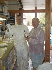
Some people on the forum say: "I don't understand all that fuzz about the proseal, it really isn't that bad..."
Forget it ! It really IS that bad... proof is in the next pictures. The guys who say that are mostly professionals that do this day by day. We -poor first time builders- don't have the skills or habits yet of working with this sticky mess and believe me... you will be happy when your first day is over.
Let's have a word about the procedure.
First you start by scuffing up the skin and touching sides of ribs and stiffeners with the maroon scotchbrite pads (very fine). Score them well ! This is important because the small scratches you make will increase the adhesion of the product to the metal.
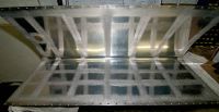
Then clean the metal very well. I used the silicon entferner of spiess hecker (the same agent as used when applying corrosion protection).
The skin and parts must be very very very very clean. You don't want any risk here of doing all the messy work to find out later that the sealant didn't connect because of grease of dirt.
Once cleaned. Use surgical gloves so that no more grease from your skin is transferred to the metal.
The next step is to apply electric tape next to the location of the stiffeners. Allow 0.5 to 1 cm next to the stifferener so you can easily make fillets. Once rivettted, we will remove the tape and a nice line will form.
If you decide not to do this, you will end up with a mess... believe me.
For the next tank, I will also apply butcher paper in between the skin parts that keep clean. The way that I did it now leads to too much cleaning work because of proseal getting smeared all over the place.
It's a mess... really... it is !
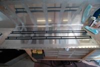
Is everything ready now ? Think now, because time flies once the proseal is mixed and minutes tick away with no mercy once the hardning agent is mixed.
- paper towels cut in 4 inch squares - check !
- aceton (in large quantities available) - check !
- popsickle stick - check !
- small syringes - check !
- squeezer ready with dies on, backrivet set on gun, pressure on air hose - check !
- 3/32" rivet gauge - check !
- clecoes and cleco pliers - check !
- rivets cleaned in aceton and dried on paper towel - check !
Now it's time to mix the sealant. As said before, I used batches of 33 grams. 30 grams of the white paste, 3 grams of the black paste.
Mix carefully. No more white color in the corners. Don't be too fast, mix until you have a nice uniform and dark greyish color.
I also opened up the garage door to cool down the place to about 15°C. This gives you a bit more time to work.
The proseal that Vans sells is of type B2.
The first letter indicates the viscosity class of the sealant. Class B sealant is the paste consistency sealant that is most commonly used in sealing homebuilt aircraft tanks.
The figure 2 means that the paste has a working time of 2 hours. It is tack free (no more sticking) after 64 hours and cured after 112 hours. (see also this link)
The time is based on a temperature of 77°F (25° C) and 50% relative humidity. Variations in emperature and humidity will affect the cure times.
Higher temperatures and higher humidity will decrease these times, while lower temperatures and lower humidity will increase these times.
Time to put on the first stiffeners. Using a popsickle stick, applied a layer of about 2-3mm sealant on the bottom side of the stiffener. Then put it on the dimpled holes and pushed it down.
You'll need some force to push it down as proseal is quite pasty. Proseal squeezes out all over, including through the rivet holes. That's good ! don't clean it off, the paste will be squeezed in and around the rivet both sides.
Did I already say it is a mess ??? oh yeah... It's a mess !
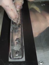
Then put the acteon cleaned 3/32 3.5 rivets in and used backrivetting tape to secure them in place. Make sure they are dry ! The aceton will affect the proseal if it's not.
I gave each of them a little push in the dimple (the paste will already ooze out a bit).
I'm not a big fan of the expensive rivetters tape and usually use paper masking tape which works as well. But in this case, you really need the good (and expensive) plastic stuff.
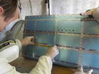
Now backrivet them. More proseal squeezes out as you rivet. (although I expected more to come out).
It is very hard to check the quality of the set rivets. The rivets are all covered with black paste and height and diameter are hardly visible.
My gun pressure was set too hard for the first stiffener making the heads a little over-set. Adjust to 40 PSI which is for me a good setting.
I recommend making a test plate upfront and practicing 10 rivets before starting so you get the right rhythm.
Used the rivet gauge (which is all covered in the black stuff to check diameter). On the picture on the right, you can see some set rivets, see how hard it is to evaluate quality.
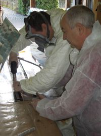
Now, put the gun aside and use popsickle sticks to make nice smooth fillets on the sides of the stiffener. Add some paste where you think it's too thin but usually there is plenty of product that squeezed out.
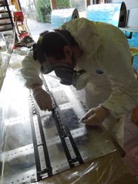
Last step is to cover the heads of the rivets with a dab of sealant.
Jacques took care of this. We tried different approaches. The syringe didn't work too well. A plastic bag with tip cut off didn't work as the paste is too thick and difficult to move in the plastic.
He had the best results with two simple popsickle sticks.
To make nice round heads, you can put some vaseline on your fingers and touch the head to make it smooth. The small amount will not affect the bonding (says the guy who hasn't tested his tanks yet).
The vaseline does not allow the paste to stick on your fingers. Just avoid using it on the sides where the paste really bonds to the metal. Some people do this too but better not take risks on this.
With batches of 33gr, you will repeat this 4 times before all stiffeners are on.
In between batches, clean the skin with aceton. It removes easily when wet. I also removed the masking tape after each batch.
Make sure there is enough room between the stiffeners because there will be a rib there soon.
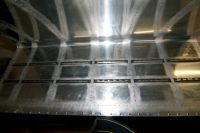
I had enough sealant left on the last batch to rivet the drain valve ring on the skin.
Applied a similar load of proseal on the inside and put cleco's in. Used the pneumatic squeezer here to set them (the only tool that wasn't dirty yet )
Then spent quite a bit of time making sure that on the coverage of the rivet heads, there was no obstruction between the rivets.
This is important to check as the water that found it's way to the lowest point of the tank has to float easily to the mid point of the drain valve. Making a small wall around it may lead to dangereous situations of cummulation of water that can finally be picked up by the flop tubes and choque the engine.
On the outside, made a nice filet around the valve as well.
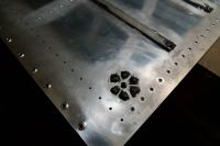
7 hours later, the stiffeners and drain are done.
Oh no... another hour to clean the mess of the tools, clecoes,...
This goes way slower then expected....
More fuel tank rivetting - 3/3/2012 - 15h
Continued work on the fuel tank senders as the evenings are too short to break out the sealant for the tanks.
I found the nice idea on another website of reusing the unnecessary T-708 access plate to make doublers for the fuel senders.
The tank baffle plate is too thin for the fuel senders so an extra reinforcement like the normal installation with fixed arm fuel pickup is desired.
I marked the size of the fuel sender plate on T-708 and then made a star shape out of it. Not because it's needed but because it's easier to cut then making a circular form.
It takes a lot of carefull measuring and trying before you get the fuel sender perpendicular on the tank and at the same time the holes to sit all at the same distance from the hole you have cut. I marked with a sharpie pen in the holes of the fuel sender and then removed soI could measure the edge distance.
When it finally was right, I matchdrilled the holes through the fuel tank sender. Use a drill stop not to damage the sender arm.
I drilled to #12 for AN3 bolts. The manual states to use 8R8 screws and #19 drilling but the predrilled holes in the fuel sender are already #12.
So decided to install K1000-03 nutplates and use AN3 bolts to have a nice and thight fit. I tried with the 8R8 but the screws are just to sloppy in the holes to be ok.
From the back side, it looks like the picture below. This is the acdtual installation location of the fuel sender, not like on the pictures a few articles back.
The sender plate goes on the aft side of the baffle and the arm goes through the hole of the baffle. The entire backplate of the sender and the AN3 bolts will be sealed with proseal on the baffle.
Then used the reinforcement plate as template to drill the nutplate ear holes to #40 in the baffle plate.
Dimpled the baffle and countersunk the reinforcement plate. Had to countersink 2 to 3 stops under to actually get the dimples to sit flush in the plate.
Used for the first time my 4" yoke for dimpling. The only was to reach the middle holes with the pneumatic squeezer.
Could also have used the pop rivet dimpler but I'm out of nails for the moment :)
Then clamped the nutplates on and squeezed them on. The reinforcement plate does not need to be sealed (just like the T-407 reinforcement ring).
It will sit on the inside of the tank and the fuel sender plate will be prosealed over them later.
All nutplates on.
Aft side of the tank.
Temporarily installed the sender with a couple of AN3 bolts.
On friday and saturday, Hugo and Jacques came over to help out with the rivetting of the ribs in the tank.
This is really a job you can't do on your own. Get help if you don't want to get frustrated.
After schuffing and cleaning some ribs, started installing them in the tank.
I learned from Hugo that I'm actually putting too much sealant as a layer on my parts before installing them.
The correct way to apply the proseal on the rib flange is to smear it on with a popsickle stick, and then go over the rib flange scraping off as much sealant so that you start seeing the nothes and holes in the rib.
Just make sure that all the surface is covered with sealant and that you don't see any more aluminum.
Slightly open the skin and slide the rib in place without touching the sides. Then finally aim and press against the skin. Have your helper install two or three clecoes.
You need clecoes in every hole. They will be messy but I think it's really required to have the hole row clamped and secured. Proseal will ooze out and that's good.
Make sure to apply electric tape the hole length at bout 1/8" of the edge of the rib flanges. This will simplify making the fillets later and will make nice and straight lines when you remove them leaving a cleaner look.
Then start from the forward end of the rib and rivet the holes one by one.
It's a mess for the bucker so it is best that the rivet gun operator keeps his hands clean.
The bucking is sticky, but I found it less stressfull then with the stiffeners. Maybe because I use less sealant now.
40PSI seemed to be the best pressure to set out rivets (3X gun for AN426AD3-3.5)
Then with the rest of the sealant, covered the rivet heads with a dab of sealant. It's better to do this first and then make the fillets.
I put a small about on a popsickle stick. Then dab it on the rivet head, make a circular motion on the sealant and scrape it on the fillet side. That was the quickest way and gave the best results.
Don't be afraid to put too much.
How much is enough ?
I kept hearing Georges voice from the video saying : "if you look at the sealant and you think, 'this can not possbily leak', then it probably won't. If you look at it and think, 'this might leak', It certainly will.
As I cleaned my popsickle stick on the fillet side, I had each time a little bit of excess sealant on the fillet.
That makes it easy to swipe the filet in one motion without the need to first add additional sealant on the fillet.
The electrical tape serves as a barrier for not covering the tank skin with the proseal.
Remove the electrical tape immediatly after finishing the fillets.
Waiting too long, or working with already hardening sealant will make it more difficult to remove the tape and will require you to walk over the fillet again as the tape may pull the sealant a little away from the skin (wires). If the sealant is still nice and soft, the remainder after removing the tape is a nice line. (see images below)
another fuel tank bay. Cleaning actually takes at least as much as long as the actuall rivetting and sealing time. Make sure there is no stuff left in the tank or lefts of rivets drllled out sticking in the proseal (or paper tissue rests,...). If you don't remove rests, it's about to get real difficult to remove them if you don't once the proseal sets permanently into a rubbery like paste.
The skin from the outside looks really cool with all these small black rings next to the head. Only a few rivets could have been sitting a little deeper but the tank dimples are deeper and make iit difficult to get the rivets deep in the dimple.
Then I thought, the tank dimples are deeper to allow some proseal to sit in between the head and the dimple so why would I wantin to set them deeper in the aluminum if the special dimples where used to do the opposite.
And here is the final stage of rivetting the interior ribs in the tank.
Fuel Tank Sealing - 25/03/2012 - 10h
I wasn't quite happy with the first fuel trap door I made. So I decided to restart. Because many sites fail (as well as the manual) to give a good explanation of how to make such a trap door, I decided to put some detailed pictures here of the process.
The function of the trap door is to slow down the flow of fuel from the inboard compartiment to the outboard fuel compartiments.When low on fuel, it will avoid that fuel flows outboard with gravity. The fuel trap door is installed on the first inside- inboard ri.
First cut a piece of hinge from the aileron hinges. There is sufficient hinge there, so don't worry. Then bend the hinge pin. Make sure you get a thight bend with a small radius. I failed the first time doing this. The hinge pin will need to be secured by safety wire and there is not much space between the tank baffle and the hinge. The flat (longest) portion of the hinge pin should cover 4 eyes. A little more is also good. You don't want the bend of the hingepin to be too close to the hinge eyes or friction will occur and your trap door won't travel by itself anymore. There should be no friction so the trap door can move freely.
Mark the top line of the hinge pin to the middle of the bottom eyer, leaving 2 eyes in the top portion and half the flat side. This will provide enough room for the hinge pin to go up and be safety wired.
Don't cut away this portion. You should draw a line from the left bottom to the top of the blue line and cut away the triangle at the top. The rest will be bend to create the 'door stop'.
Here is the result after cutting away the triangle and bending the leftover to 90 degrees.
Now mark the right eye of the bottom hinge. We will cut this away as the hinge is now to longe for the 2 inch door. The bigger, the more friction.
Here is the result. The reason why the top hinge is longer is because it will go over the punched area on the rib. You need the distance to be able to set a rivet outside of the punched area in the rib.
Don't forget to make a doubler in the same gauge material as the trap door.
Now drill #40, dimple the tap door and countersink the hinge pin.
little test fit after drilling to the rib. Note that I left a small gap underneatch the door. This is both for the clearence to the fuel tank sealant but also to allow little quantities of fuel still to flow left to right or right to left.
In case the fuel trap door gets blocked for some obscure reason, fuel will still be able to leak through at slow rate.
Then, set the rivets using a squeezer for the fuel trap door. AN426AD3-3.5 shoud do.
Note in this picture that the fuel trap door is not fully horizontal. I actually put a little angle in it to follow the shape of the rib.
Then rivet the top hinge to the rib and installed a .032 safety wire to secure the pin.
Securing the pin at this point is not really necessary as the baffle will lock the pin in place. There is no way it can get out of there once the baffle is in place. The secondary function of the safety wire is to remain distance between the pin and the hinge (to avoid friction locking as mentioned above).
A view from the backside.
I also installed and pop rivetted the anti hangup guide on the inner rib. The purpose of this anti hangup guide is to prevent the flop tube of getting stuck between the rib and the stiffener. I gave it a little twist and the curve makes the head of the flop tube nicely slide down. Two lp4-3 pop rivets hold it in place. No need to get noisy with solid rivets. Make your life easy where you can.
A close up of both installed.
After making a first attempt of making a simple anti hangup door on the inspection door side, I got interested by another design on a couple of builder websites for an alternative way of installing the anti hangup guide without obstructing the inspection door entry when removed. I made and remade the angles and finally came up with the design in the picture below. This would probably work for installation but a long discussion with buddy builder Fred convinced me not to do it and go for the simple anti hangup as vans described (blocking the entry mid way). This is again a place where you don't compromise builders ease for safety. A weak point in the design as in the picture is the top side of the tank (right side in picture) the distance from the last support Z angle to the top of the tank is still quite high which makes that the wear and tear may make this part bent, creating a new possible safety hazard by locking up the flop tube.
I started thinking then about the reason for this anti hangup guide. It looks like there is no real reason for an anti hangup here when using floptubes. The only reason I could come up with is that the antihangup guide creates a distance between the soft flexible flop tube maze and the bolts sticking out of the nutplates. If these would touch, it would always be at the same place and in the long run this could create leaks there that could lead to air suction on low fuel levels possibly leading to fuel starvation. a big no-no. So you want this anti hangup guide. I remade my original one (seen in a few article back) in a thicker gauge as I thought the .025 was too light and flexible and would de-form after time.
So again, before you get the wrong idea, the picture below is a no-go. eventhough it's easier for maintenance. My final piece is visible some pictures below.
Some days later, I went to buddy builder Hugo for cutting the whole that will pass the AN6 fitting of the flop tube through the nose of the inboard rib.
I don't have a drill that is big enough for this hole and Hugo had just the right tool for it. Another one for your shop list at Avery or cleveland tools : the Rota-Broach set
The problem with this assembly is that the combination of the support angle, the reenforcement plate and rib is just too thick to use the unibit. The rota-broach cutters make a nice deep and precise burr free hole through all three at once.
Pay attention when positioning your rivet holes around the big hole. Keep in mind that the nut will come on top of the elbow for the fuel flop tube and that it needs to be able to spin. Keep enough distance from the support angle vertical part and from the rivets so the but can spin.
Remade that anti hangup in .032 sheet, the old classic way with limitted accessibility.
There is a service bulletin of vans that says you have to safety wire the flop tube nut to the elbow. Safety landings have occured with people that complained about fuel starvation with a half empty tank. The nut slided off the elbow leading to a high point fuel pickup.
This was my first safety wire job and I am quite proud of it. It turned out well.
I saw on some websites a good idea to avoid rotation of the flop tube elbow by vibration. Many builder have used the fuel pickup support angle from the fixed fuel pickup to support the flop tube. I did the same. Just cut off some teeth from the support and position it nice and horizontal on the rib. Once rivetted on, the flop tube can no longer have the tendency to pivot on the elbow. The only moving part will be the flexible part of the tube.
Position of the flop tube when installed towards the anti hangup guide.
Another view at the flop tube elbow attachment.
Outside view. Middle is the air vent elbow outlet. Make sure this points slightly downwards as you will still have to install a aluminum tube on that later. Setting it straight would make it difficult to build on to it later.
Then, it was time again to start mixing fuel tank sealant and put the outer rib in place. The outer ribs are much easier then the inner ribs since you can do these using the pneumatic squeezer.
First installed the modified T-715 anti rotation bracket. Then rivetted the anti hangup guide on the inside of the inspection door.
Then installed the rib and made fillets on the edges making sure there is a nice bed of sealant on the side.
Then applied sealant to the rib reinforcement doubler T-410 and to the T-405 attach angle.
Bucked the AN470AD4-7 rivets and then torqued the AN924-6D nut on the AN833-6D elbow using 150inch/lbs. Put some sealant on the elbow before inserting but make sure there is no sealant on the threads.I used masking tape to insert the elbow as the sealant makes a mess upon insertion.
Add a lot of seanant on the leading edge side of the rib as that seems to be the place where most leaks occur.
This is how the tank looks with all ribs, vent line and fuel system installed.
Close up view of the end of the flop tupe.
Position of the flop tube in relation to the anti hangup guide.
Flop tube over stiffener.
Left tank is ready for closure. I will first do the same now on the right tank.
Right tank sealing - 21/04/2012 - 9h45
After completing the inner ribs on the left tank, it's time to tackle the right one. I deliberatly wait with closing the tank until both are ready to do so.
There are a couple of reasons for that. The most important one being that there is literally a ton of clecoes to be cleaned after rivetting on the baffle plate and I don't feel like doing this twice.
When you will be as far in this process as I am now, you will understand why.
I taped of the areas that need to stay clean around the stiffeners, this makes making the fillets easier while working. I used cheap electric tape for this.
Keep a couple of millimeters distance from the stiffener. Make sure to keep enough room where the rib will come. The sealant that connects stiffener seal with rib seal will anyway be produced when you install the rib.
A new thing I tried after doing the stiffeners on the left wing tank is to put brown paper on the rest of the skin surface. It takes a bit extra work before you start but will save you two hours of cleaning skin with aceton after you finished and a lot less mess.
After 5 hours, the stiffeners of the right tank are backrivetted on.
The started working on the inner rib to install the access plate accessories on the rib. As you may remember from the left wing, the rib arrives uncut in the wing and you have to cut the circular opening for the access plate yourself using a fly cutter.
This went very smoothly. Then deburred the edges of accessplate, inner stiffener ring and rib using the die grinder with 3M wheel and sandpaper.
Next step, install the stiffener ring. According to the plan, you should first put the access plate on and use that for match drilling. I found it difficult to perfectly locate the position of the access plate to be dead center and is was easier to start with the stiffener as this one can be perfectly aligned with the cut whole in the rib.
The only thing that you have to check before starting to drill is that the holes line up well with the hole position of the access plate. Remember that the access plate has a straight edge on one side that should align with the extrusion in the rib. That will give you an approximate position of the holes. Use a sharpie pen to mark them. Then position the stiffener on to align with those hole and in perfect alignment with the cut edges. Use clamps to fixate.
Drill for #8 screws with #19 drill and cleco as you go.
Then drill #40 for the nutplate ears. All of this can be done at once while the stiffener ring is clecoed on.
Then add the access plate and matchdrill that one with the #19 drill through the already cut holes.
Next step is dimpling the rib nutplate ears. (carefull on the direction !). Dimples are facing IN, flanges of the rib OUT.
Then, countersink the stiffener ring. You will need to go seriously under flush. The usual 2 teeth extra on the countersink will not do. Important is that after countersinking, when you match the stiffener ring in the dimples, that the stiffener lays flush on the rib. I had to go 5-6 steps under. The test rivet sits fairly deep in the stiffener countersink. The reason I guess is that the rib web is fairly thick. This gauge takes place in the countersink you you'll need to countersink some more to have a nice mating situation.
Then for rivetting, I use crock clecoes to keep nutplate, ring and rib well attached. Setting the cleco a bit to the side still provides enough place to pass with the pneumatic squeezer head. So, some #8 clecoes on the sides for overall mating, then the two rivets in , nutplate on and clamping the nutplate on with a crock cleco. Then squeeze.
The result is really outstanding. Nice rivets from both sides.
But more important, look at that mating of both pieces. Nearly perfect. No opening at all.
Next step will be rivetting in the 5 inner ribs in the right tank.
Right wing tank work - 29/04/2012 - 16h
My buddy Fred made the vent line for the left tank. Now it's time for the right tank so this was my first experience with bending, cutting and flaring aluminum tube.
The vent line is 1/4inch and is still relativly easy to manipulate and bend.
First step, unroll the vent line and try to make it as straight as possible. The tube comes coiled up so you need to unroll gently.
Then you cut it to length. Cutting aluminum tube must be done with a tube cutter tool. A hack saw is too aggressive for this work. The cut needs to be really smooth to make sure that the aluminum does not create cracks when performoing the flaring operation.
Position the tube cutter on the aluminum tube to cut. The wide support in the bottom of the tool goes on the part of the tube you want to keep.
To cut a tube, put first light pressure of the circular cutter wheel to the tube (light pressure) and rotate the tool gently.
When you return to the orignal position, the cutter should be back in the same location where it started (low quality cutters may have difficulty doing that when the wheel is able to swivel a bit).
Once rotated, give the black know a half turn and rotate the tools again once or twice around the tube. You will feel the pressure get less. As it floats freely, give it another half turn.
Repeat this until the cut part falls off.
In preparation of flaring, use sandpaper on a block to sand perpendicular on the tube. Also deburr the edge in circular turns (no scratching along the lenght of the tube but circular around the edge). This will allow clearence for the sleeve later on.
Don't forget to deburr the interior of the tube. You will be surprised about the difference in radius in the tube before and after. (putting pressure while cutting can make the radius smaller by burr building).
Then you need to bend the vent line for the offset from the predrilled hole and the position where you put your vent line elbow in the outerrib. I made a drawing on paper how I wanted it and then bent the tube using fingers and bend-sleeve.
Then installed the line in the tank and clecoed the inner rib in. Surprisingly, this did not need a lot of tuning.
You can easily adjust the bending while the tube is in the tank.
Important here is that there is a close match between the nipple of the AN833-4D elbow and the tube. There should be no tension at all or otherwise said, you should not have to pull the tube to get the tube on the nipple. Tension may lead to stress and cracks. Maybe not as critical with this vent line but life-critical when working on the fuel lines. So you better get it straight from the first time.
You see what I mean in the next two pictures.
Next picture gives a better idea about the offset of the vent line. Also look at the inner diameter of the tube. This one is nicely deburred. If your's is smaller, you forgot to deburr.
Then moved on to create a new vent clip. This little piece of aluminum has to be constructured from .025 scrap aluminum. Make a nice bend in it. Nothing is critical here. Just make sure the tube sits thight in the clip and that the clip is aligned with the line of the vent tube.
Next step, drilling the reinforcement plates that go in the nose of the outer ribs on the rib. I installed the rib, held the plate on the inside and marked with a line the position of the reinforcement plate. Then remove the rib and repositioned the place along that line.
Then clamped and drilled #30.
Made the anti hang up guide for the inner rib. I actually made an inverted copy before from the one in the left tank. So this was easy. Drilled #30 and installed them using a LP4-3 pop rivet.
Secured the nut on the AN833-6D elbow for the fuel line on the pickup tube according to vans service bulletin. Things were a bit different as with the left one. The nut holes for the safety wire here ended up on the other side then with the left one. Therefor, I had to 'go around' with the wire to be able to get the locking function on. Make sure you check twice on the direction here. You want the safety wire to lock the nut when you loosen it, not when you thighten it.
Installed the anti rotation bracket for theflop tube and drilled it's holes #40 and dimpled the two holes in the rib. Countersunk the holes on the bracket.
After a lot of reading, research and discussions, I finally fot to the point of making a flare myself.
The picture below shows a nearly perfect flare. I had to restart it 3 times before I finally got it in my fingers. There was also a bit of dirt on the rollo flare tool head so I had some markings on the inner aluminum extrusion. Again probably not critical for the vent line but I wanted things to be perfect so restarted until it was good. If you are wrong, cut it off after the flare and restart. Just make sure you have enough length left for the length that has to go in the rolo tool.
The question is, 'how much is enough, and how much is too small'.
I discussed this with various people and finally came up with the following theory.
The width of the flare had to match the width of the widest point of the sleeve that goes over it. I tested this and then found the table below online. When I measured it, I found indeed the same numbers. You'll get the catch in the pictures below.
In the table, you see the width in mm of the diameter for the outer borders of the flare.
There are different numbers for the fuel line 3/8 then for the vent line 1/4. I marked the numbers in the table below for the vent line.
Now how to you use the rollo tool to make a flare ?
I could describe it here in detail but there is a very good video shown at EAA video's at http://www.eaavideo.org/video.aspx?v=3727487ut 001
I got the right diameter with about 8 half turns of the arm of the flare tool.
I eye-balled it when making the flare and then tested with the width of the sleeve. When I measured it later on I found that I had indeed the minimum required diameter.
I got the right diameter with about 8 half turns of the arm of the flare tool.
The picture below shows the same flare with the sleeve on. That's how it should look. Notice the outer edge of the flare is nearly equal with the outer edge of the blue sleeve. If I would go little wider, I would be equal to the sleeve and possibly be very close to .350 which is the ideal width.
Below you see how it looks like when you hold this sleeve on the nipple of the AN833-4D elbow.
Then attached all back on the tank and re-matched the fit. Perfect !
On sunday, I got back to rivetting on the fuel tank. I had two more ribs to do on the outside.
I took some more pictures for the beginners with sealant. This is more or less how it looks like when your rib is inserted and put in place with cleco's.
On the outside ribs, the sealant should ooze out of the flange. You can nicely see it here in the picture.This is about the perfect quantity.
I used the squeezer to set all those rivets. Then Peggy helped me with shooting the 1/8 rivets in for the reinforcement pieces in the end of the nose. The ones on the fuel cap side are really a pain as you can hardly see, light and buck in there at the same time. I ended up using the next next length rivets for the outboard side plate. Probable used a little too much sealant in between so the heads were a little short at first. The remaining 5 were at longer lengths and more then sufficient.
Same on the inboard side. Here we had to install the reinforcement angle that holds the front of the wing to the fuselage and which is also the place where the fuel comes out through the AN833-6D elbow as shown in the picture below. Applied lots of sealant as these are the places where most people encounter leaks when testing.
All installed on the inner rib
Fuel cap installed and fuel vent line bend up. The rivetting of the fuel vent clip went much easier on the right rib.
Fuel cap cleaned top side.
Covered up generously all rivet heads with sealant. In the picture you also see the blob over theAD6 rivet that covers up the tool hole in the midlle of the rib.
Use electric tape when rivetting, this will produce the nice line as you see in the picture. It is virtually impossible to do this without taping and you will have hours of cleaning work after.
Inside view in the first bay after installation
close up on the flop tube front of the inboard rib. (fuel pickup-
Installed the drain valve inboard. This time also used small strips of electric tape to ensure openings between the blobs on the rivet heads so water can float to the lowest point.
Again the vent line in the fuel cap.
Next mission is closing the tanks. But now I'm off to Chicago again for two weeks. Work will continue after that.
Preparing for tank closing - 15/5/2012 - 6:30
In the last three work sessions, I have been working hard on making everything ready for tank closure. Once the baffle plate is rivetted on , there is no way back.
I made a list of things to do but as I started working, I kept on finding new stuff that was remaining and the checklist kept growing and growing. Kind of frustrating if the end line is in sight and they keep pushing it back.
First important task to do was rivetting the K1000-3 nutplates on the z-brackets. It will soon be very difficult to do this once the brackets are rivetted on the tank baffle plate. I deburred and countersunk them months ago so this went smoothly.
Left wing brackets
And right wing brackets.
I also found out that I still had to deburr the side edges of 3 of the z-brackets that I reordered.
One of the Z-brackets has no nutplates as the nutplates of the inner z-brackets are mounted on the spar and the bolts are installed here in the opposite direction.
Then constructed the right tank fuel trap door. The idea of the trap door is -as the words says- to trap fuel in the lowest compartiment on low fuel levels.
For details on working steps, see the articles in the left fuel tank work. I described the process step by step in those articles. Don't forget that for the right tank, things have to be inverted.
Lessons learned today : If you are in a hurry, or make a plan, you mess up...
Don't plan time, you'll get frustrated and you will never keep up. Ask me how I know...
So what did I mess up this time ? Nothing big, but by rivetting in the end ribs in the last session, I found out that I had no more room to put my rivet gun or squeezer in so I had to use CS4-4 pop rivets here to attach the upper hinge bar to the rib. Not a drama, but again one of those occasions where you think: 'I got away with this one but next time think ahead !'
Side view.
Rear view
Important here is that the fuel trap door does not get stuck halfway. This can happen if there is tention on the hinge pin. Make sure it is loose so don't put pressure on the safety wire. I plan on putting some sealant on the pin so that it stay always in the correct position al of the time.
On the right tank, my trap door does not spontaneously fall against the rib. when very light pressure is applied, the door closes completely. I think this is ok. It may be because of some sealant on the bottom of the rib. I will try to scrape a bit away before closing.
Some more tasks on the checklist without pictures:
- deburr the flanges of the right tank baffle plate
- scuff the top side of the ribs
- seal (or glue if you want) the fuel cap holder in the fuel cap ring.
- torqued the vent line nuts AN818-4D as specified in service bulletion to 50 inch lbs (corrected mid value for crowfeet extention)
- installed the fuel sender reinforcement ring on the baffle of the right tank. Countersunk the plate, dimpled the baffle and installed the nutplates
- bent the fuel tank sender float at length and cut to length.
I have been thinking again about the AN3 bolts to keep the tank sender on the baffle and on the length of the AN3-4A bolts or to use the 8R8 screws anyway like on the plans. I find that the 8R8 screws don't match the predrilled holes in the fuel tank sender attach plate.
The pictures below show the length with AN3-4A when using a thick washer. The second picture show the length when thightened. I believe that the washer will not be required. I will install them without washers.
The mandatory Service Bulletin No. SB 06-2-23 on fuel tanks also says that the forward ring must be sealed on the front of the flop tube. The rubber ring is easily removed
Sealed on. (the little block is just to keep the tube up and is not part of the structure.
Pay close attention to clean any excess sealant of carefully. This is the place where the fuel gets sucked in, you don't want any obstruction of the flow here. Make sure no sealant is on the openings in front or on the side of the pickup tube.
Temporarily installed the baffle plates on both tanks. I taped electric tape close to the baffle to form the filets.
I saw that the ends of the ribs were not fully aligned anymore with the baffle. Putting clecoes in pulls them back in place.
I was as good as ready. One more evening to go to scuff some final parts and test and inspect the tank a final time
I was all excited that I was actually about to close both tanks the next day.
Then I noticed that on the right tank, my fuel sender does not fit the holes in the correct orientation.
AAAAaaaaargghhhh!
Some month ago when I drilled these holes, I drilled them on the wrong side of the baffle plate. The sender is the correct one (C for the right tank), baffle fits the tank, how can I have possibly been mistaken here.
This is how it looks
Damn indeed, I did invert them. look at the picture below, this is what happens if you do it wrong !
The sender sits nicely straight, but on the opposite side of the tank. If you turn it around, the holes don't match anymore. The only way the sender fits is bottom up, which is as you can imagine not ok...
I felt warm and cold at the same time.... man, the baffle is a large piece. High cost for shipping... lots of rework... oh no...
I can tell you, this is the normal process...first there is the frustration, blame yourself of the stupidities you did.
2nd phase, you start thinking on a solution without replacement of the screwed up part.
In this project, you will have a lot of situations like this. No matter how hard you try not too.
Look at it as a learning process. If you can't handle that, don't even think of starting to build yourself.
There are a couple of options here:
1. replace the baffle, the most expensive and time consuming one.
2. I can try with another left hand sender. This L-one fits the same holes. The sender is centered in the bay so it will also work with an L version. The L and C version are actually important if you mount them on the access cover platwith fixed fuel pickup).
3. cover up the hole as small as possible just outside the holes and install the fuel tank sender in the 3rd bay. (seemed to be a no-go because of the 3rd bay being a higher wing position)
4. Invert the fuel sender plastic on the fuel sender attach plate. (This soon seemed impossible)
5. Cut out the whole attach structure with reinforcement piece from the baffle to about 3.5 inch diameter. The picture below shows with the short blue lines where that would be.
Then I can cut another 5 inch circle out of some 040 stock sheet material and cover the hole up by rivetting the cover plate on and installing the fuel sender on the new cover plate that will be permanently sealed in place.
I decided to go for option 5, but slightly modified the idea.
I will order a T-407 ring and a T-411 tank access cover plate. Since the baffle is still loose and accessible, I can rivet the inner ring in without problems. In this way, it will be more or less like the inspection cover on the inboard rib side of the tank.
I will install the stewart fuel sender on the access cover. This will certainly facilitate maintenance work if ever the fuel senders have a problem.
Actually I'm even thinking to do this also on the left baffle plate for future maintenance reasons. I am still waiting for confirmation by Vans support that this is structurally ok. I will update the post when confirmation is received.
This way, a mess up turned out to have a positive outcome.
Unfortunatly, I will have to wait for the parts so I will continue on some other parts for now.
Fuel sender access port - 02/06/2012
On monday 28th of May, we had a builder meeting in the workshop of Hugo. In the image left to right: me, Fred and Hugo.
Hugo is currently working on the fuel lines and fuel pump. Lot's of usefull info for later. As usual, a planned 3 hour meeting ended up late at night.
In the meanwhile, my replacement parts for the fuel tank baffle have arrived. As you may have read in the previous articles, I messed up the direction of the fuel tank sender plate on the rear tank baffle. (in other words, inverted the position of the fuel tank sender by drilling from the wrong side. Dummy ! I still can't believe I really did that).
Saturday 2nd June, I started installed a new reinforcement ring T407 and access plate T411 in the second bay of the fuel tank baffle. Van's gave green light to proceed this way and it is actually a good way to have access later on to the fuel senders in an easier way.
I first made a drawing to have an idea of the size of the access plate and centered it using the middle drilled holes for the z-brackets as reference. Removed the old doubler plate and rivetted on a small aluminum plate over the hole.
I needed to do this because otherwise, the fly cutter would not have a place for grip to guide the cutting process.
Using the fly cutter, making the hole was a piece of cake. You can see the temporary rivetted guidance plate in the picture below.
Then aligned the reinforcement ring on the inside of the tank baffle for matchdrilling. Crock cleco's do a great job here.
All matchdrilled
Then dimled the tank baffle (mind the direction !) and machine countersunk the reinforcement ring.You have to go quite deep on the reinforcement ring to make a nice mating of ring and baffle (without opening between the two). This is because the baffle is relativly thicker then regular skin.
Then using a lot of clamps, rivetted the nutplates on. The clamps make sure the baffle is pressed nicely agains the ring while rivetting. I also always put a crock cleco on the middle of the nutplate to press it against the ring.
Nice job done, the tanks are ready to be closed now !
Further on, I deburred the edges of the main wing skins and finished to machine countersink the main spar of the left wing.
Closing the tanks - 03/06/2012
A long awaited day has finally arrived : the closing of the tanks.
After numerous hours of small final things to do (scuffing, fuel sender installation, flop tube sealing, trap doors, torqueing vent lines, ..) and lot's of checking and double checking, we finally came to the point that the tank can be closed.
Fred offered to come and help. He has a quickbuild so he didn't have to do this kind of work and he thought if would be an educational experience for him. Little did he know about the mess that was awaiting him.
I wanted to do both tanks at the same day to have the tedious job of cleaning cleco's only once. Try to do the same thing. There are a TON of cleco's to use in this process and cleaning them is a nightmare.
In the beginning of the fuel tank work you need a couple of cleco's and there is little cleaning work. Later you need many to rivet the ribs and the repitition of cleaning them after every couple of ribs in each session gets really boring.
In the end, you need an army.
It turned out to be a marathon session of over 12 hours but we managed to get the job done.
The day started by preparing surfaces with silikon entferner (Zbracket, baffle, ribs and skin)
Then made a batch of 130 grams of sealant + 13 grams of accelerator. This turned out to be just enough. Made little extra to twirl the rivets in.
I followed the manual and made a 6/32 layer of sealant on the inside (passed the holes) on the skin. Not too wide, just enough to get it pushed forwards and make the fillet on the inside. Not too much because otherwise it will block of the water drain (small notch at end of rib bottom side).
Then applied sealant on the inner flanges of the outer ribs. Again, not too much, just enough to serve as fillet.
Put small blobs on the rivet holes on the inner ribs.
What's not in the manual, but I read that many people do it to avoid leaks, is to put a light layer on the flanges of the baffle over the entire length. I did the same on the place where the baffle meets the in and outboard rib.
Placed a heavy glob of sealant in each corner. Then I put the baffle in place. First put the topside in and then have the bottom side slide in nicely.
Then you cleco all ribs and skin to baffle connection points. This is where you really need 4 hands. In total time, it would take too long when you do this alone and the sealant would become too hard towards the end of the procedure.
First you put in the pop rivets top and bottom side of the baffle. (the ones that are not on the z-brackets).
Once these are done, you can start rivetting the skin to baffle. The squeezer works great here. As you see, the sealant oozes out a little. This is good !
Some of the rivets are standing a little proud, but within acceptable range.
On the right tank, we had some problems with alignment of the baffle and skin making the rivets sit a little sideways. Here also, not the nicest but it will be no problem.
This is how the baffle to skin looks like with the way that I applied sealant.
Van's makes some remarks in the manual that says you should put c-clamps between the clecoes to get out excessive sealant. I did not notice any curtaining and also I don't see how you can get a c-clamp in between each cleco.
Some rivets squeezed, hundreds more to go.
This is really teamwork. One takes out the cleco and puts a new 3/32 rivet in place. The other adjusts the squeezer, sets the rivet and checks the result. Again, time is critical when closing the tank.
After both rows or skin to baffle rivets are done, you rivet the Z-brackets to the baffle and ribs using pop rivets.
The z-brackets have a small flange and high web, so you need to modify a rivet puller by grinding off it's nose. (Thanks Hugo for letting me use yours).
Pay special attention to the orientation of the z-brackets ! The flanges all point outboard except for the outer ones. Look at the orientation of your tank and the flange direction when you do this. It will be really difficult on a closed tank to drill these out if you mess up.
Twirl the pop rivets in sealant before installing. It will look like this when set
Fred pulled the nose of the puller down while I used both hands to snap them off in one single pull.
Then you use the squeezer on the AD470-4-4 rivets in the outboard ribs for the two outer most rivets. Pay attention to take the correct ones (I had to drill out 3 of them (one of them twice) because of not paying attention and probably also caused by fatigue).
The inner rib to baffle to z-bracket needs to be done with the rivet gun. No way to access with a squeezer there. They are AN470AD4-5 rivets and setting them was easy.
Then cleaned the outside of the tanks with aceton. You can really see that the sealant is hardening by the time you are able to do this. It get's tough to remove the sealant from the skin side. So do it immediatly after finishing the tank. Don't wait until the end when both are finished or you will have a lot of fun with the first.
Then clean all your stuff. The picture below shows the amount of cleaning work. Pay close attention to the huge amount of clecoes.
A little close up shot of the inboard top stide of the left tank.
Both tanks finished. Only the access plates left. I will do those in the next days.
Next step here would be to pressure test the tanks. But I'm going to wait for at least 3 weeks before doing that so that the sealant has enough time to cure.
One more batch of sealant to make to cover the access holes and the tank sealant T-shirt will be burned !
Closing access plates - 10/6/2012 - 4h
After spending a day in Fred's workshop yesterday - helping with the parking brake installation -, I returned to my own shop for a short work session in order to close the access plates on the tanks.
I first prepared some fuel tank sealant to permanently seal the fuel sender to access plate connection. These are installed with 8R8 screw. Dipped the screws in sealant before fastening as the manual dictates.
Make sure the bending of the fuel sender arm is acurately tested before closing the tank baffle. It is impossible to see in the second fuel bay once the back baffle plate is rivetted on. Mine were both tested installed on the baffle plate but shifted one bay inboard so that the empty and full position where clearly visible and reached to the extents of the tank.
The first picture shows the fuel sender mounted on the access plates and the arm in the down or 'empty' position.
The second picture shows the fuel tank sender in the 'full' position. An electric wire will bring an ohm value between 25 and 300 to the cockpit to display the fuel level.
I will be using the Dynon skyview system. This system allows you to calibrate in the glass flight deck the min and max ohm value for empty and full.
To install the access plate, I decided to use the cork seal gasket ring until the final installation. Using the cork to seal the access cover plate is not a good idea in the long run. Many builders have reported leaks starting at the cork gasket once it starts getting saturated with fuel after a couple of years. I will remove the cork gasket on final installation on the main spar and will then close the access plate with fuel sealant.
This is how the cork looks when layed over the opening in the fuel baffle plate.
Then installed the access plate using 8R8 screws.
The same procedure on the inboard access plate.
Et voila ! The tank fully closed and ready for the leak test in a couple of weeks.
I also installed the drain valve. Be carefull when doing this, the drain valve should not be screwed all the way in.
It is impossible to do this. This is 3/8 NPT pipe thread. Screwing the hole thing in WILL DAMAGE the dain flange in the tank. The drain valve is steel, the flange is aluminum, guess who willl win if you use a wrench and a lot of force ?
The correct procedure is to apply fuelube on the threads of the valve screw (half way, not on the top) and then screw it in "fingerthight". Then take the wrench and give it 1/2 to 1 turn with the wrench. This is more then enough.
I will still cover the rivet shop heads on the fuel tank baffle in the coming days but the real structural work on the tank is now completed...
Thank God !
Tank wrap-up - 21/07/2012 - 5h
In preparation of installation of the top skins, I had to put the fuel tank on the spar. I remembered I still had to cover up some rivets heads on the tank baffle and replace some of the rivets.
I first installed the cork gaskets on the access doors and tried to pressure test the tank. I soon found out that the cork did not stop air from going out via the access plates.
To avoid any other problems with them, and after inspecting the interior of the tanks one last time, I decided to seal them with proseal without the cork gasket. The cork gasket is known to cause leaks after 4 to 5 years.
Here is the sealed fuel tank sender access plate on the tank baffle.
There is an inconvenience with this approach of not using a cork gasket. The flop tube has a shelf life and needs to be replaced after a number of years. In that case, I'll have some annoying task of removing the sealed access plate.
Then gave it another try.
Installed the fuel tank test kit which consists of a cover nut for the fuel line, a pump valve that goes in the drain point through which you can inflate the tank. I also made a smal pipe that is mounted with regular flare and nut on the vent line to install the balloon.
Also taped the fuel cap with duct tape.
Be carefull when pressurising the tank, especially if you use a water level. The pressure in the tank may quickly exceed acceptable levels causing permanent damage to the tank assembly. Go easy with the air input and do not use a air gun. Just use a bike pump. That will do it. You will be surprised how little air you need to put in to inflate the balloon.
The balloon was fine for the entire evening, but ... the next day it was deflated. damned !
I'll have to try this again with the tank off the spar and using soapy water to test for small leaks.
Fuel tank leak test - 3/9/2012
Time for some testing of the fuel tanks.
I started by pressure testing the left fuel tank.
This procedure can be done in different ways :
- using a balloon on the vent line
- using a hose with water on the vent line
- using water and soap while the tank is pressurised to detect small leaks
I find the water test dangerous as it can actually damage the tank if you put too much pressure to raise the water level.
The water and soap is kind of messy and forces me to remove the tank again.
I decided to take the most simple way, which is the balloon. Vans sells a fuel tank test kit which contains some plugs that you can use to seal of the fuel tank line and a air intake valve that you plug in the tank drain valve.
It is good practice to tape some duct-tape over the fuel cap to prevent small leaks there.
I have tried this test a couple of times and failed each time. The balloon would be deflated after a day and sometimes after an hour.
It drove me absolutly nuts and I stated to get convinced that there was a leak in the tank.
I found out that all of these failures were not caused by the tank but by the guy setting up the test.
Some advise:
- use a new balloon (one of my tests showed a leak in the balloon (deeeeeuuuuHHhhh!)
- tighten the cap and the inflation inset well. (one of the test leaked air on the air intake)
- use a piece of scrap aluminumtubin of the vent line to make an extention on the vent airline output. There is no way you can attach a balloon to the AN fitting.
- use an elastic strap to attach the balloon to the aluminum tube (duct tape is not enough,another reason for failure).
I finally got all the details straight and inflated the balloon on friday 31st of August.
This is the balloon on wednesday 5th of September.
The difference in distance in which the picture was taken is misleading. The balloons are still equal in size.
I think I can easily conclude that the pressure test on the left tank is successfull and that there are no leaks !
Yeah ! High five for the good guys...
Right tank fuel leak test - 9/9/2012
On wed 5/9, I repeated the balloon test on the right side fuel tank.
This time, payed close attention to the setup of the test.
I measured the circumference of the balloon at the start of the test and measured 76cm
On sunday afternoon 9/9, I removed the balloon and it was still the same size. Peggy measured it as 77cm which may be a slight measuring error, or the difference of air temperature.
In any case, I concluded that this was a successfull test and that the right tank has no leaks !
I forgot to take pictures as I was very busy on Sunday trying to move the wings from the wing jig in the cradle. At the point we moved them to the cradle, the balloon was still on but I realised then that I would have to remove it to fit to the cradle.
This concludes the work on the fuel tanks.
Wing Jig - 3/7/2011 - 6h45
Finally finished the inventory of wing and fuselage kit. This took in total about 21 hours. Inventory for the main parts is pretty fast and easy. The time consuming part is the counting of the hardware (little screw, bolts, nutplates, rivets...)
I'm very impressed of the acuratness of the content of the kits. There are hundres of parts and everything was in the box. The fuselage kit was completely ok. The wing kit had one bag with washers where they messed up some quantities so I will contact Van's to let them know they should add some washers to me next order. But overall. Pretty impressive service !
My DGLV inspector has requested me to complete the wing jig also in front of the inspection of my empenage so he can check for straightness and robustness.
The only plane he ever failed was because of a tilted wing that was caused by a wrongly aligned jig. So he is really punctual about wing jigs.
Building the wing jig is not a fun part. You spend a lot of time doing it and have the feeling that you are stalled in the building process. Nevertheless, it's probably one of the most important fixtures you'll ever make in your lifetime.
Because of the measuring and constant checking for straightness, you will go very slow. I planned on doing this in a day but finally, here is the result of 7hours of work spread over 2 days.
Why2 you may ask ? well, I got frustrated after the first one and decided it was better to call it a day :)
The wing jig consists of 2 support beams in wood of 6cm by 17c. The two main posts are made by 2 beams of 5cm by 12cm screwed together with bolts. It is better to have 2 then 1 big one.
Key here is to make sure your get straight beams of wood.
Overall I'm pretty happy with the result. They are level in both directions. I'll check again when I receive my digital level after the summer holidays.
Next job is to do the same thing on the other end of the garage at 114inch or 2m90cm distance.
Wing jig completed - 14/8/201 - 4h
It took three weekends but now finally, the wing jig is completed.
In this last stage of construction, I attached aluminum angle attach horns to the 4x4 wood posts.
On the outboard side, I attached a fixed angle that will hold the W712R rib just under the spar with 2 AN3 bolts. It is sufficient on this side to have the bolt (and thus the hole spar) level on both vertical and horizontal side.
Then I attached the inboard side of the spar to the other posts with a horizontal alu angle which is supported with a 45° angle piece of angle. I made an opening in the angles so that I can still adjust the position later on by just loosening, positioning and tightning again.
This is the idea of what you should finally get when you will start levelling the spar in the jig :I will make a close up picture and post it here soon of the inboard side attach angles.
Below are some pictures of both spars levelled in the jig.
The measurements along the spar are now level but this is not precisely true. The spar has some sag in the middle. Once the ribs and rear spar are clecoed in place, it will need some support in the middle to remove the sag.
At that point, it will be possible to get it completely level along the complete length.
Put some masking tape on the aluminum angles to protect the spar when clamping it.
Leading Edge Cradle - 09/12/2011 - 2h
As I'm starting edge prepping on the leading edge ribs, I realised I am behind on the construction of my jigs.
Therefor, I took 2 hours to make a nice leading edge jig.
As per the plans, I used one of the ribs with some millimeters extra to allow for padding some soft material
Divided my hardboard in 2 using the measurements on the plans and layed the rib parallel with the rear part aligned with -what will become- the top side of the jig.
Then used a jig saw to cut out the forms.
Then used some left over bars from the shipment boxes of the fuselage kit to attach to both sides of the jig plates.The plans call for 2x4" s but this is also more then sufficient. I used some steel angles to connect them by screw.
Finally I cut up some old carpet and stapled it to the form that will hold the leading edge skin. I made sure to give it a couple lf extra taps to make sure the staple is completely in the carpet so that it can not form scratches on the skin.
Eh voila... all finished and ready for some leading edge work.
Building the wing cradle - 02/09/2012 - 6h
The main wing structure is now rivetted on the top side and ready to be removed from the wing jig. The wing structure is now rigid enough to stand on it's own.
This means woor work !
I made the wing cradle out of MDF plate and 2 by 4's. It may be a bit heavy build, but I can tell you after some hours work with the wings in the cradle, that the wings sit very stable and I can drill very precisely.
First made some drawings on the MDF board using the drawing on the plans as template.
Then cut it all out
Made the bottomframe by connecting the 2 by 4s and using the leftover cutoff plates to make some support for the wheels.
Bottom side:
top side :
Put the side panels on and then waited from some second hand swivel wheels.
I also used the cutouts to support the upstanding plates.
A week later, I got the wheels mounted, broke down the wing jig and installed the wings in the cradle.
16/02/2020 - Wing closing and inspection - 4.5H
Wing closing time... These have been in the cradle for so long. One of the next milstones is mating the wings. For this I will need to bring the whole plane out on my patio to assemble. Before we can do that, the bottom wing skins must be rivetted. I had to leave these open because of the inspection by the belgian aviation authorities. I got green light after inspection so now I'm ready to start rivetting.
The finishing kit box comes in very handy as a table to support the wing.
First I started inspecting the wing interior for remaining tasks. One of the things I recently found is that many people put some RTV on the wing ribs and conduit in order to keep them from moving.
Next I found out that I didn't put the middle AN bolts in on the fuel tank Z brackets. Installed those and torqued and sealed all of them. Putting torque on bolts in a nutplate is in my opinion not really accurate as the nutplate sometimes is soo thight that the bolt isn't set yet and the wrench already clicks on 25 inch/lbs because of the resistance of the nutplate. I put them in completly and then applied the torque. Inspected and double checked all bolts were in place. Also installed all 8R8 countersink screws that hold the tank to the spar.
I noticed SB 16-03-28. This talks about annual inspection of the aileron hinge for cracks on the rear spar. The SB says it's not necessary to replace on finished wings. My brackets are already rivetted but the skin is still off so the bracket is still very accissible. If you read through the SB, it's actually quite challenging to apply this on finished and closed wings so I decided to remove the brackets now and order the parts for the SB and apply it now that it's still easy to do so. I'll have to be very carefull drilling out the rivets. I sent a mail to support and they told me that larger fasteners will not be allowed by engineers on these rear spar holes. Making an error here is not an option.
Closing the wings is done by rivetting in an L shape. You start on the rear spar wing walks and move up gradually. It's very thight in there and challenging to evaluate the quality of the set rivets.
I purchased a USB android inspection camera and this works really well.
Here are the first set rivets on the rear spar. It's all rivetting blindly on feeling.
some more
Here you see the camera in place and the android tablet showing the real time image.
This is how far we got in this first session. Not much but at least it's a start.
20/02/2020 - right wing inner bottom skin - 6h
Continuing closing the right wing. Inner skin rivetting. This is really a slow and unpleasant work. Working blind, guessing if your rivet is coming out good.
Not ideal for anal guys like myself. I'm using the usb camera and it helps but it remains a very slow job.
Made some shots of the finished rivets.
Here is some rivets at the aft spar.
and some on the inner ribs
The last image shows what has been completed and also gives a good image of what you see on the tablet through the camera.
as you can see, not a lot done in 6hours time. Some people do this in an afternoon. I can't get my head around it.
22+23/2/2020 - Rivetting right wing inner bottom skin - 5h
Not making a lot of pcitures here. Just the same repetitve work over and over again. Still moving slowly.
Keeping working in an L shape pattern toward the joint with the outer skin.
This is as far as I will take the right wing before the outer skin comes on.
I will now continue on the inner skin of the left wing. I'll explain why in the next article.
28/2/2020 - drill out inner aileron bracket - 2,5h
I mentioned in the previous article that I would move on the the inner skin of the left wing before starting the outboard bottom skin.
I had a good reason for that. Vans published a service bulletin (SB-16-03-28).
In this service bulletin, Vans Aircraft explains that some airplanes have on their annual inspection encountered some cracks on the rear spar of the wing at the inboard aileron hinge and there is a potential for cracks at the flanges of the inner aileron hinge brackets. In the service bulletin, Vans also says that this is not a mandatory modification but that the location should be inspected carefully on each annual inspection.
They also mention that a preventive action on already completed wings is not recommended and that the change should only be done by someone experienced in sheet metal repair.
When you read through the steps of how to fix this issue, you immediatlaly understand why. This is NOT an easy fix once the wings are finished.
This put me thinking if it would not be a good idea to implement this SB as a preventative measure now that the wings are still wide open and the aileron bracket is easily accessible.
My aileron hinges are off course already rivetted to the rear spar so I started doubting. I asks Vans Support and they did not recommend it. They said that I should be very carefull when drilling out those rivets of the aileron hinge not to damage the rear spar. They advised backing up the rear spar with a bucking bar while tapping the rivets out. Some days later, Michael from Australia came by (who build and fliies a sonex) on a holiday trip to Belgium and visited my workshop. I showed him the SB and my hinges and his thoughts were the same as mine. So I decided to go for it. I will need to order those SB 16 brackets so I 'll have to wait with closing the outboard skins for now.
Fortunatly I have been drilling out a lot of rivets and I became more or less an expert in this. I carefully center drilled all rivets and was able to easily pull them out with no damage at all.
My process is the following. I center punch the rivets, The rivet has a little center notch in it and if you are lucky you can still feel if after setting the rivet. (sometimes the rivet head expands a bit and the hole gets closed)
Then I use a very small drill bit to drill the center hole. Then switch to #40 to the depth of the head. Then you pull out the head and punch out the rivet with a pinpunch and hamer or sometimes I use the pinpunch to click it out.
Here's a shot with all rivet heads removed.
Then punched them out (like Vans suggested) backing up the rear spar with two tungsten bucking bars on each side of the hole. Then gently tapping them out.
Tis image is the doulbler on the aft side. As you can see below, the holes came all out undamaged.
The next image is the inner side view of the rear spar. Here also totally ok.
One thing less to worry about. I'll do the same on the left wing after rivetting the inner bottom skin on.
29/02/2020 - closing left wing inner skin and inspection - 5h30
Today I started on the left wing. Just like with the right wing, I went through a thorough inspection of the inside. Are all rviets there that should be there ? Check.
Installed all the remaining tank AN515-8R8 attach screws. Vacuum clean the inside (yes things do get dusty after years in the wing stands. Spiders and bugs tend to like the lightning holes in the wings).
I ran the green pitot line and the blue AOA line. These came with my safeair static kit.
I also installed the stall warner electronics with the stall warner vane in the front of the wing and connected the electric wiring for gound and current back through the center bushings of the wing.
Here are some shots of the instpection. The first one of the wing walk ribs. You can see the wiring and the larger conduit. The conduit will be used for running the electricity of the wing tip lights.
Here is a shot of the aileron bellcrank. I will have some more work on this because I don't like the way the floppy wiring runs underneath the belcrank and can be a possible cause of friction or worse blocking of the system.
These are the primary steering controls, you don't want to take any risk with that. Some builders have made a special bracket that attaches to the aileron brackets and I'll probably do that as well.
Since this is just passed the inner skin, I can leave this for a later date and continue on the bottom inner skin now.
Then fitted the bottom inner skin and start rivetting again. Same process as for the right wing. Work in a L shape pattern starting at the aft rear spar working your way out and up towards the main spar.
I meanwhile understand that this is only critical for the wing walk ribs and the first bay next to it. The others can be easily reached through the lightning holes if needed.
02/03/2020 - Pitot mast reinforcement - 2h
As I don't have a rivetter available all the time, I decided to take on some other small jobs.
One of the remaining tasks is to make a reinforcement bracket to support the pitot mast.
The only attachment foreseen is three rivets in the flange of the main spar and this is not sufficient for stability. It could lead to cracking due to vibration and you don't want that in your wing skins.
I already added the 6 rivets on the side and in the outer skins earlier. Now I started making a reinforcement angle bracket that is rivetted to the wing rib and which supports the bottom plate of the pitot mast.Cllamped it in place and drilled the holes using the holes in the mast as a drill guide.
Two holes drilled
And here is the result, the three holes drilled and bottom skin installed.
Next, I found a new victim to come and help me out with rivetting the skin. Shot a couple of rivets today. Reaching out to the back is really painfull for your neck and I could not do long sessions at this at once.
It was a long time ago I could motivate one of the kids to help me out on the plane. This time Matthias , meanwhile 16 (boy time flies), helped me out shooting the gun.
He is doing a great job at it. An aircraft mechanic in the making. Too bad he doesn't know it yet himself :)
05/03/2020 - Pitot tubing work and some rivetting - 4h
Some more solo work done today. No rivetter available for the skin so doing some other remaining tasks.
One of them is cutting the aluminum tubing of the pitot mast and flaring the connection points.
I have the dynon unheated pitot mast which features aoa line and pitot line.
These are very thin tubes so be extra gentle with them.
Some stretch marks visible, but no cracks.
I temporarily fit the connection points and installed in the mast.
Some people bend the tubing and ring it all the way to the wing rib. I opted for the other option of cutting it at the end of the mast and running flexible wiring from there.
Put some thread sealant on the connection points and screwed on the gold colored fittings with the special locking mechanism by safeair1 that will receive the flexible lines.
Did some more rivetting after that. I squeezed both lines of rivets on the very first inner rib. This can be reached with a pneumatic squeeze so it could be done without any help.
07/03/2020 - Left wing inner bottom skin closing - 4h
18/04/2020 - Rivetting, pitot line and some touchup work - 3h
Did some more rivetting on the left wing inner bottom skin. My parts from Vans finally arrived so now I can continue thinking on fully closing this sucker down.
I had to be pretty sure about the pitot line routing.The way they are arranged in the picture below makes that the two lines are not touhing or chafing.
I installed an adel clamp on the main spar (actually enlared an already existing pilot hole and attached the adel with a 8R8 screw and washer and nut on the other side.
This just ensure that the line would not move around by vibration.
The SB 16-03-28 parts finallty made it to my home (it's corona times here and everything is delayed. On top of that my first shipment got lost by US Postal and had to be resend).
I cleaned up the parts, deburred and installed them on the rear spar for match drilling. No big deal. Deburred the holes and scuffed them up for priming tomorrow.
I also noticed that in the front of the cabin, the vent lines were touching the F7105-B outboard sub panels. Should have bend them a bit lower when I made them. Good reminder for the next RV7 I will build (yeah right...)
I marked the places that interfere and carefully filed a bit away.
Same issue on the other side. I deburred it all and reinstalled. Looks very good now. Enough spacing not to cause any touching by vibration.
Same other side. The amount taken away is really small. Will touch it up with some primer.
Continued some more rivetting as well. This is about as far as I can go in L shape before the outer wing skin must go on as well. So time for a final inspection of the outboard section of the wing.
19/04/2020 - Pitot line support bracket - 3h30
The pitot line and aoa line are two hard plastic lines that pass from wing rib to wing rib through some snap bushings in the left wing.
At the last bay, the lines pass underneath the aileron bellcrank. The distance between the ribs is to long to provide for a proper support of the lines and I did notice some potential for interference of the lines with the bellcrank.
Or at least touching. Which would lead to wear by vibration. Therefor I decided to make a little extra attach bracket to support the two lines right underneath the bellcrank.
I used some 0.032 stock sheet and marked the area needed.
Then used the little bending brake from home depot to make a nice 90 degree bend.
Did some measuring and marking which part has to be trimmed away and drilled two corner holes for rounding.
Went couple of time back and forward to the wing to check the width and fit.
Then removed the aileron bellcrank and used that as drill guid. First hole was faily easy. Just use the aileron bellcrank bracket as drill guide.
Then reassembled the bellcrank hinge and clamped the other bracket. This ensures the correct spacing between the two holes.
Drilled two holes for the bushings
Et voila, a home made bracket.
After fit install, I decided to make another hole in the middle as it looked even better when the pitot line (green) would be a bit higher.
Finally withthe time left, I primed some small remaining parts including the new bracket.
20/04/2020 - pitot line final and rivetting aileron hinge - 4h
Did some more rivetting on the skin and also made a final installation of the pitot line and bracket.
I sent these pictures also to Vans support to get their opinion on my pitot routing as I wanted to make sure my installation is good.
I inversed the green pitot tube to the middle bushing also on the left side which means I had to pass the electrical wire of the stall warner through the bottom hole. This way, it interferes a bit at the pitot lines because iit comes through the main spar about just in the middle at that location. I asked support if it would not be a better idea to make an additional hole in the spar bit lower for passthrough and route the stall warner through there.
This was the response of Sterling from Vans Support on the routing:
"The routing looks good.
As for the stall warner electrical wire I would recommend just connecting the wire and AOA line using RTV. You can apply a large dab of RTV onto the line and then bed the wire into this. That will tie them together and prevent any chance of the wire chafing on the AOA line latter in life.
Sterling"
So that's what I will do. Here you see a close up image of the bellcrank passing.
21/04/2020 - rivetting bottom skin - 2h
Just a small update with only one picture.
Continuing rivetting the left wing inner bottom skin.
A slow process that needs a lot of patience. I am getting better at using the camera and semi blind rivetting but still it's certainly not going at the speed I expected.
I read that some people do this in a day. I really don't understand how that is possible. I'm probably too critical again but then again, I have to fly this thing one day...
22/04/2020 - Rivetting left wing outer bottom skin + small tasks - 4h
Like Sterling suggested in his response on my pitot routing question, I used a big dab of rtv to attach the stall warner electrics line to the pitot line. I did this in two locations as the wire crosses the tube in two locations.
This secures the wirte against the pitot line and no chafing can occur now.
The inner skin is as far as I could bring it. Now it's time to bring the outer wing skin on.
First I had to rivet the inner aileron bracket back on using the additional brackets from the service bulleting on the inside of the rear spar.
I spotted a problem here. The brackets interfere with rivetting of the top skins. No way you can get a bucking bar in there.
The aileron bracket is also not possible to rivet on later without. I prefer to inspec these rivets up real close so decided to first rivet these.
Here you get a better view of the inside of the bracket.
I asked a question to Vans if cherry max rivets would be allowed here.
This is the response from Vans Support:
"Yes, you could use Cherry Max rivets. There are some blind rivets available that can be utilized that are designed for #40 holes and dimples without having to enlarge the holes or change the dimple/countersink size.. CCR-246SS-3-x (x=length, 3 indicates 3/32 rivet replacement). You would have to determine what grip length you need (x). Most like a CCR246SS-3-2 would work."
I googled the rivet number but couldn't find anything. I did find something under CCR264SS-3 which sound like what he described so I'm pretty sure they inversed the number.
Outer skin on the left wing, rivetting time again.
23/04/2020 - left wind outer skin rivetting (cntd) - 3h
25/04/2020 - rivetting left wing bottom skin final - 5h
28/04/2020 - flap brace rivetting and pitot mast -
Squeezed the left wing flap brace using the pneumatic squeezer.
I also had to shoot some more rivets on the angle that attaches the pitot mast to the wing rib. I didn't make this angle in the first place but decided that it would be more firm and less prone to developing cracks if the pitot mast is supported by the wing rib. I made the angle little earlier, primed it with some other parts and now it's ready to be rivetted in place as wel. This is shooting and bucking. No room for squeezers.
The ones on the rib were too difficult and I decided to use cherrymax pop rivets for those 3 rivets.
The skin rivets were set with AN426 rivets.
Inside view.
01/05/2020 - Right aileron bracket - 2h
Started closing work on the right wing today. Just like on the left wings, I preventivly applied the service bulletin on the inner aileron attach brackets.
I had drilled and primed the parts earlier so now it's time to rivet the aileron bracket back on.
I had some issues with 1 rivet that I had to drill out twice. Came out with a bit smaller manuafactured head in the end due to the drilling but it still looks acceptable.
I guess it's one of those things to add to your annual inspection list.
Another shot from the top
After some vacuum cleaning, the right wing is now ready to receive it's bottom skin.
Since I have the experience of the left wing, I hope closing this one will go a bit faster.
04/05/20020 - Right wing closing 1 - 3h
Started rivetting the inner part of the right wing skin. I won't repeat the details as the process is the same as on the left wing.
Work in L-shape. The part under the wing walk doubler is the hardest. But by now, I got the hang of it and it went a bit smoother as on the left one.
I won't be posting many pictures and focus on the work to speed up work a bit.
I'm working in short 3 hour sessions and doing a bit at a time.
05/05/20020 - Right wing closing 2 - 3h
06/05/20020 - Right wing closing 3 - 3h
Another good rivetting session, got almost to the end of the rear spar. Those are actually not really fun to do. I'm using the crowbar shaped bucking bar to set these. The reaching in is quite a long distance and it kills your back being in that position. Went all the way up to the 3th row and half way the 4th on the outer skin. This is going smoother than on the left wing.
07/05/20020 - Right wing closing 4 - 1h
09/05/20020 - Right wing closing 4 - 2h
11/05/2020 - Measuring the terrace as apron parking space - 2h
Today I have been measuring a lot and drawing different scenario's on the terrace floor to find the ideal angle to put the plane.
Most important was manoevering space around but also having it in a safe location so that people won't bump into it by accident when they visit me.
The blue lines show the final decision. Tomorrow, my stepfather will come over to move it out and allow it to smell some fresh air for the first time.
12/05/2020 - Moving the plane out of the garage and attach wings - 5h
It's out of the garage !
I know it has to go back in after mating and will have to be disassembled again after this but still , it's a big achievement to finally see a plane in your garden.
First we carefully brought the plane out and positioned it according the measurements I made yesterday.
I put the seat floors (bottom skin) on 4 wood pallets and also installed some pallets in the back. Used the same cradle as in the garage to support the tail.
I have put some screws in all wood to avoid sliding and shifting if heavy winds might show up. After all, it's still May and we may still have some heavy rain and winds coming over Belgium in the next weeks.
And I'm also thinking of summer storms.
Mating the wings went surprisingly well. I read about people having problems sliding the wings in, being too thight and having to manipulate the mainspar (A BIG NO NO !)
Mine went in really smooth, fit like a glove. Installed the temporary bolts.
Put something under the wing to support it if only 1 is on ! (Ask me how I know). The plane almost tipped over on one occasion while we were installing the other wing.
Here it is, in all it's glory. What a terrific sight.
15/05/2020 - Mating wings, measure, measure and more measure - 8h
Every hole you drill in your RV will be an important one, BUT. If there is one hole where you can really really not screw up, it's the hole for the AN5 bolt that attaches the rear spar of the wing to the attach fork on the fuselage.
At the same time, this will be the most exciting moment in your build so far as you see the plane assembled with the wings on. Vans says that this process of mating the wings can be done one wing at a time. I would strongly advise against that. Maybe a professional builder could do that, but we amateurs need every reference we can get. Find a good space to mate both wings at the same time.
So many things are defined by this single hole that it makes you dizzy when you just think about it.
The hole defines:
- the sweep of the wings (forward backward)
- the inclination of the wings (angle of attack)
- the triangulation of the wings (equal distance from center point on tail section)
On top of that, you need proper edge distance on all parts once the hole is drilled. The tabs are really small and there is not much room for play.
If there is one thing you don't want on these things, it's insufficient edge distance. The bolt will tear out under the tremendous stresses on the rear spar of the wing.
Multiple accidents have happened already due to drilling mistakes in this part. You will loose your wing if the bolt breaks out ! The sinusoidal effect of the vibrations will tear your wing of it that bolt is gone.
All this to say that you need a fresh mind, patience and brainpower when you take this next step in the build process. Don't take it lightly, it's not one of those thing you do in an afternoon.
First, make sure the whole fuselage is level in all directions. Measure on all possible locations. Starting from a non level fuselage is asking for a disaster to happen.
The measurements are not all that difficult. You hang plumb bobs on the inner and outer top skin of the wing and do this on both wings. Pull a string underneath the plumb bobs.
If the wings have no sweep, the plumb bobs will be exactly over the string.
To make sure you have no left or right sweep, you measure from a common rivet at the end of the wing (I took one on the main spar) and measure up to a point in the center of the tailsection of the fuselage.
I used the center notch on the top of the F709 bulkkhead). Triangulate. If the distance reads the same from the left wing to the tail as from the right wing to the tail, the wings are straight.
Now the wings are in the right positions, you can set the angle of incidence. For this, you make a small tool with a piece of angle that lays on the main spar and has a little offset on the end of 3 inch which stands on the rear spar.
You then lift or lower the wing and make sure you angle reads level. You can see the drawing for that home-made-tool in the right hand top corner of DWG38.
Needless to say this reading is only correct if the top longeron of your fuselage is also level. If your readings are correct, your wing will have a 1 degree tilt up incidence on the chord of the wing.
You can measure that using the tool to align the ailerons and placing a level on that. The level will read +1degree.
I only found that out later but it's usefull as a cross check.
I measured the whole day, scratched my hair multiple times and left it at that.
Here is a picture of the place where the hole will be drilled for those unfamiliar with the RV-7. The hole will go through the white square and through the rear spar (green)
17/05/2020 - More measuring mating wings - 8h
Today and yesterday, I continued measuring all distances on mating the wings and making small adjustments.
I could not get the forward sweep of the wings better as my rear spar was somehow blocked by somthing before the spar even touched the fuselage skin.
After a lot of trial and error and many times removing the wing again, I found out what caused this problem.
In the image below, we are looking behind the rear spar. This is the forward side (the photo is taken from the back facing forward).
Whe you look in the little mirror, you see the top corner of the fuselage fork F-605C (bar doubler) primed in white.
Next to it is the W-710 inboard rib. As you can see, the flange of the wing rib is touching the F-605C and prevents it from moving more inboard.
Here is a close up shot showing the obstruction problem. You can also see that the wing comes in at an angle and that only the top part of the flange touches the F-605C
The solution to this is easy, remove the wing, and remove a little bit of the material of the F-605C only on the top side so that the wing can slide in further.
Here is a picture of the wing removed again and in black marked on the F-605 where I need to remove a bit of material.
After some iterations, I got the distance to be good. I also had to remove a little bit on the bend of the rear spar where it touches the AN470 universal head rivet. Now the wing slides all the way in and the sweep is good.
Then next step is to determine the center point on the F-705-B center bar. This is where the hole should be drilled in ideal conditions.(just to have a reference point for now.
You estimate more or less where the rear spar sits inside the fork. I made a cardboard template when the wing was removed showing the contours of the spar. Then inserted the wing and positioned the cardboard over the rear spar.
Now you can draw some lines on the fork.(the left vertical line shows where the spar sits on the inside, the rear spar came out lower than the fork so no need for a horizontal line in the bottom). Then connect the corners to find the centerpoint. This is the point where edge distance will be ideal.
I had some time left and mounted the empenage to the plane.
19/05/2020 - Drilled the holes mating the wings - 10h
Yesterday 18th, I had another full day of measuring and finetuning. Basically trying to convince myself everything was perfect now and ready to drill the pilot holes.
I kept reading small variations of 0.1 degree on the incidence measuring between inner and outer area's of the wing. (only weeks later I found out that my difference was caused again by something I learned before but forgot about over the years. The wing walk doubler actually has also some extra height under the inner wing skin and adds a fraction to the level. So that most inner reading is actually normal to be tenth of a degree of).
I decided to take the shot and with shaking hand drilled the first #30 pilot hole in the fuselage fork and through the rear spar on the left wing. I used a metal block with a predrilled hole on the benchdrill to ensure holding the drill straight.
I immediatly checked the position of the hole on the forward part of the fork and saw that my vertical line indicating the predicted location of the hole was quite accurate. Edge distance on the fork looks perfect.
Then did the same on the right wing.
Also here, the hole location on the back looks very good.
To make sure all was fine, I took both wings of again and measured the fuselage attach fork edge distances as well as the distances on the rear spar itself.
As you can see in the pictures below, edge distance is fantastic on all parts.
Het is the rear spar on the left wing.
Rear spar on the right wing.
Then it was time to enlarge the hole for the final AN5 bolt size on the left wing. I used an undersize drill bit and finally enlarged with various reamers until I got a snug fit of the AN5 bolt in the hole.
All still looks good.
Then did the same procedure on the right wing.
This is how it looks with that massve bolt inside.
As you can see, there's plenty of edge distance in the rear spar attach.
One thing worried me a bit. Altough I used a drill block to make the initial pilot hole and have it straight, I found out that the bolt sits a bit tilted in the fork. Reason, using the wrong rivet line to look if the drill bit was held straight.
I hate it when such stupid things happen. I contacted Vans support on this and suggested to add some filed washers on an angle to support this and have a flat surface.
This is the response of Sterling on this:
"Filling a set of washers to match these angles and gluing them to the face of the fuselage bars would be an acceptable work around and is all I would attempt to do. Other than that what you have appears to be perfectly acceptable. I expect this assembly would be fine without the filed washers but if you add them it arguably should be on both sides so the bolt head and nut are on flat matting surfaces. Might require the next size up bolt be used."
left wing final size hole edge distance.
The tilting on the bolt is better on this one but also still slightly tilted. I'll go with the filed washer solution on final assembly.
20/05/2020 - Bottom skin pairing and wing root fairing drilling - 5h
Now that the wings are mounted and drilled to the rear spar attachpoint, it's time to some small tasks that should be completed now that the wings are installed.
First task is drilling the fuselage bottom skin to the bottom wing skin. Both skins will be held together with screws and nutplates.
While the wing was off, Vans has you draw some reference point on the bottom wing skin in order to remember where the holes underneat are. The idea is to measure back and drill through the fuselage bottom skin and hope that you end up close to the pilot hole underneath. I made the markings as a reference, but decided not to go that way. I hate guessing when it comes to measurements.
Here is a shot of the bottom side of the wing skin. behind the drain point, you can see the overlap. This is work to be done on your back, a very uncomfortable position and a killer for your neck muscles.
Instead of using the reference lines, I used a hole doubler to find the exact location on the fuselage skin using the pilot hole of the wing skin underneath. This is the most precise way to do it but it's not that easy as the spacing between both is really thight but it can be done. I used the markings on my reference line to easily locate the hole underneath.
In the image below all are drilled #40 and some have been updrilled to #19 (the black clecoes). I updrill to #21 and then use a #19 reamer to make the final hole.
Then I repeated the process on the right wing. I found out later on that I actually made too many holes for attach screws compared to what the plans say. Well, it's gonna be stronger in the end having some extra screws so no big deal.
I had some time left and started installing the wing root fairings on the right wing.
Draw an edge distance line on the tank so you can locate the faring through the predrilled holes. It takes some "massaging" to get the right form on the front. It's thight but fits well.
An additional difficulty is making sure you don't end up drilling in the tank sealant of the fuel tank. The last thing your want to achieve here is a leak in the tank.
The bottom side view of the fairing
I started drilling from the bottom and then pulled the skin over.
In the picture below, all the holes are drilled #40.
Then they get enlarged to #40.
All fits nicely, final drilling and reaming to #19 for 8R8 screws.
The fit looks really smooth and thight. The fairing rest pretty close to the fuselage skin. The plans indicate on DWG38 that the gap between fuselage skin and fairing should be between 3/16 and 1/4 inch.
This distance will allow a good fit for the rubber band that slides over the edge of the wing root fairing.
21/05/2020 - wing root fairing top side drilling - 5h
One of the things that you should do now while the wings are attached to the fuselage is the installation of the wing root fairings.
This is a piece of aluminum skin skirt that covers the opening between the inboard side of the wing and the fuselage side skin. All this to make a nice joint that finally gets filled with some rubber baind.
To ensure edge distance, draw the minimal edge distance line on the tank skin. This helps locating the position of the fairing by looking through the predrilled pilot holes in the fairing skirt.
In the picture below, you can see the red line through the holes.
I drilled the hole that is common with the tank skin to #30 so that I could put a copper cleco in the nutplate of the tank skin attach.
Drill the other holes #40 to start with. You will notice that getting closer to the common hole with the tank skin intersection, it gets impossible to follow the minimal edge distance line.
Not much you can do about this as the fairing is pre drilled.
A view of the bottom side of the fairing. Form the leading edge of the fairing. Do the same trick of drilling #30 the tank attach hole. There quite a lot of pressure on the skin at first. As you form the leading edge better, the tension gets less.
Check for a nice connection between tank skin and fairing. Then enlarge the #40 holes to #30, then #22 and finally ream to #19.
The distance between the fairing has a defined gap between 3/16 and 1/4 inch. This will allow sliding a rubber seal band over the side of the fairing skirt.
In the image below, you can see that I made black markings in various locations from the fuselage skin to 3/16 inch.
Connect the dots and file away the excess material. The image below is how it looks like when done. Re-measure the gap at various places.
I looked for the rubber seal and put it in place over the first couple of inches. Looks really nice. When installing this permanently, you use some soapy water to easily slide the rubber over the aluminum skin.
Next I noticed the flap skin was really close and butting against the fuselage skin. I will do some research work on what this distance should be and will take care of that in the next session.
22/05/2020 - Adjusting flap gap with fuselage - 2h
I ended yesterdays article with the following picture. As you can see, the flap skin is way too close to the fuselage skin.
There needs to be a gap here to allow safe travel for the flap. This is something you can't measure upfront and will only see the first time that you rig the flaps on.
I looked for a value in the manual but couldn't really find an indication how wide this gap should be.
I asked the question to Vans support and Gary answered that he removed a little material on his 7, but not more than a millimeter or so.
That still looked very little. I looked some further and found an artigle on vansairforce that discussed this issue. One guy said he had 1/16" gap before and had issues after a while with the skin of the fuselage being marred and damaged because of the flap touching the skin in flight. He said he enlarged the gap to 3/16" and never had any issues anymore later. So I went for the 3/16 gap.
While the flaps were installed, i measured the distance from the fuselage sik on the flap at various locations. Then connected the lined and got myself a cut line.
Then carefully file away the excess material with the vixen file and some key files. Test and install a couple of times to fine tune and then sande and edge deburr.
Same process on the other flap.
23/05/2020 - aligned right aileron, start flap actuator hole - 4h
Now that the flaps are moving freely next to the fuselage side skin, it's time to start thinking about the flap pushrod hole in the fuselage belly.
In order to find the neutral point of the flaps (flaps up position), you need to ensure that the ailerons are fixed in the neutral position and then align the flap with the aileron.
So the project of today is setting the aileron 0° neutral position on both wings.
To do this you need to adjust the pushrods that go from the aileron bellcrank to the aileron hinge itself.
Vans supplies a little jig cutout from aluminum to fixate the aileron bellcrank in it's neutral position.
This jig is inserted between the bellcrank and the pushrod and secured by an AN3 bolt.
Adjusting the length of the pushrods will move the aileron up or lower depending on the direction you turn the rod end bearings.
On the end rib, you have to attach a piece of straight edge or aluminum angle where you have match drilled two holes with the predrilled tool/align holes of the outer rib.
Extend the outer edges of the holes with a sharpie pen to extend the parallel lines. Then bolt the angle to the rib to secure it in place with some AN3 bolts.
These two holes in the rib define the chord of the wing (in other words the zero degree angle reference).
The whole point of rigging the ailerons is making sure the aileron is following the chord line of the wing.
In the image below, you can see the result you are trying to achieve.
The trailing edge of the aileron should be perfectly between the two lines defined by the chord of the wing.
This gives you the neutral position of the aileron.
With this position defined, you can now align the trailing edge of the flap with the trailing edge of the aileron and all will be in it's neutral flaps up/aileron neutral position.
I clamped flap and aileron togehter with some vise clamps.
Next step is making the passthrough hole for the flap actuator through the fuselage bottom skin.
There is a pilot hole drilled by Vans but I wouldn't trust on this. Make your own estimation on where it should be.
There is little documentation on doing this so I'll describe how I did it.
I attached the rod end on the flap actuator and attached it to the flap. Then move the flap up and hold the rod end against the bottom skin to have an idea where it will pass through.
You want to make an initial whole to have the actuator pass through and then fine tune it from there as the flap moves up and down.
In the end you will get a peanut shape through the bottom skin of the fuselage.
There will also be material cut out of the side skin of the fuselage which looks more like an arc.
In the image below, you see my initial markings on the bottom skin where the rod end touches.
You will cut out one of the bottom rivets as well. I was puzzled about that initially but it's normal to have remove one of the rivets.
I leave it here for today and will make the cut in the next session. to be continued.
25/05/2020 - Fuel tank attach bracket - 5h15
Jumping a bit from left to right in the build process and decided to attach the fuel tank attach brackets to the fuselage. These brackets stabilize the fuel tank in front of the wing.
It's a steel bracket that is bolted to the fuselage side skin and attaches the fuel tank attach bracket with a 'loose grip'.
One hole was already drilled when I made the fuselage side skin. Now it's time to hang the attach bracket perpendicular to the side skin and drill the second hole #12.
The regular way of doing this using a center line marked on the skin and then cleco the attach bracket to the top hole. Center the line in the hole of the bracket and match drill the bracket using the hole as a guide.
The bracket held in place with a vise grip. You may need to slightly bend the attach bracket in the last inch to have it mate perfectly with the fuel tank bracket. Mine fit without tampering with it.
In the next image, you can see the centerline through the bracket (green).
And drill the hole, deburr
Now the fuel tank attach bracket can be bolted to the fuselage.
Clamped the bracket back onto the fuel tank attach bracket and drilled the hole through the back slot for an AN4 bolt.
As you can see, this is a 'slip bolt'. The bolt will be held in place with a large washer and a nut.
The reason why this design as such is for safety reasons. If ever you end up in a crash and the nut would be thight in a regular hole, then on impact the fuel bracket may tear out of the inner rib, destroying and opening the fuel tank.
Imagine that happening with lot's of fuel in the tank. Not a good idea. Instead, this slip bolt construction will safely detach the tank from the fuselage on impact without destroying the tank.
Here's a shot with the washer installed. There is no nut on at this time. Notice how the attach bracket butts nicely against the tank bracket without gap.
Same work now on the other wing.
Clamping
And drilling the hole leaving lot's of edge distance all around.
Both wings are now fully mated to the fuselage. Another step to remove from the to-do list.
26/05/2020 - flap actuator hole, stick rigging - 7h30
While I was playing with the flaps, I made a first attempt to center the control sticks by adjusting the rod end bearings of the aileron control rods.
Getting very close to 90 degrees. It 's almost impossible to get this perfect on 90. half a turn on the center pushrod moves it too much to one or the other way. This is as close as I could get it for now.
After a lot of try and error work, I finally finished the flap actuator hole in the fuselage side skin. The flap moves freely to the full up and full down position.
Using key files and a dremel with grinding wheel, I managed to make the perfect shape.
Move a little at a time, insert the pushrod again and move the flap a bit lower which will move the actuator to front and outboard. Mark "where it wants to go", and file a bit more. Then try the same thing again until you reach the full flap angle.
To save some time, I taped some transparent plastic on the hole and marked the contours to be copied on the other side.
I wasn't planning to do the full cut based on that but it would give me a very good idea how and where to make the first cut on other side
bottom view
In the next images, I transferred it on the other side showing where the hole has to be made.
side skin
27/05/2020 - checking measurements and finalising flap holes - 3h
Today, I took some pictures of the measuring process and readings on the wing mating procedures for later reference. I thought it might be usefull to show where I measured.
First of all, measurements of the fuselage read level on all horizontal stations. 0.0
Then measured lateral level along the longerons, on the 704 and on the tail section (along the skin which is level with the longerons below)
along the tail top fuselage skin and on the aft deck supporting the horizontal stabilizer.
On the next image you see the angular alu strip which I use for aligning the ailerons along the chord of the wing. There are 2 tooling holes in the outer wing rib which are used to define the chord.
Match drill two holes through these rib holes and secure the angle with an3 bolts and some washers underneath so that it passes the aileron hinge.
I measured on the chord and get the perfect 1 degree angle of attach. (defined by drilling the aft rear spar attach hole on the inboard).
To cross check, used another digital level. These things have some 0.1 degree inaccuracy so better measure twice and verify with the average of the reading. In this case, both read 1.0 degree.
The way the inboard attach hole was drilled was done by using a digital level and a small tool that you have to construct yourself. The tool rests on the forward spar and has an offset on the rear which rests on the rear spar.
When setting the angle of attack, your level should read 0. (See some articles before where I explained the drilling of the rear spar attach hole for more details on the process.)
Here are my readings at various stations on the left wing that lead to the 1.0 degree incidence in the previous picture.
Same measurements on the right wing
I double checked here also with the inclinometer and got slightly different readings. This shows how inaccurate these things can be if you're being truly "anal"
Measured the other chord angle of attach and reading 1.1 degree. That's not exactly the same as the other side and was a bit of a surprise for me.
By the time of drilling I didn't think of measuring on the chord using this alignment tool and only based myself on the measurements on the wing above.
So do yourself a favor and measure also along the chord although the instructions don't mention it.
.1 degree is close to nothing so I guess it won't get significant effect from this. Not so long ago, people build airplanes using air bubble levels. Guess that was less accurate then the digital level.
checked alignment on the left aileron using the tool.
and measured the neutral position angle.
It's difficult to measure this exactly as the aileron will give very slight different readings along different stations on the aileron
Here is a shot of the measurement I wrote on the flow in 0 degree and full flap extention at 40° flaps.
Measurements on the right wing aileron
Sticks neutral 90°
The alignment tool rigged tgo the right wing and checking aileron trailing edge in neutral position.
The following pictures show the alignment of the flap and aileron of the left wing on the neutral position
Same picture on the right wing.
Measuring deflection on the right wing flap. neutral and extreme down position. In the extreme position the flap can go down to 44 degrees.
Here is how that looks on the inside on the flap actuator side. When the flap is at 40, a nice gap remains between the fuselage skin and the actuator so that the actuator doesn't chafe against the skin.
Deflection measurement on the left wing aileron.
Measuring deflection on the aileron on the right wing.
right wing summarized
left wing summarized
After all that measuring, couldn't resist getting into the plane and taking some shots.
In the following pictures, I took some close up shots of the finished flap actuator holes in the fuselage.
Bottom view
Side view
Some different angles
View from the inside
Inside view with the actuator installed at full flap up position.
30/05/2020 - a visitor
02/06/2020 - bending fuel line - 4h
While the wings are attached to the fuselage, it's a good moment to make the fuel and vent line connections from the fuselage side skin and the wing pickup point on the fuel tank.
I soon found out that this small task actually will turn into a nightmare.
I have installed Andair gascolators on the fuselage side skin and my entry point of the gascolator on the fuselage in relation to the pass through hole in the fuel tank attach bracket is just too short.
I tried several times bending and tweaking but can't make a satisfactory result.
The bending tool is just too wide. The first bend is ok, but the next bend is so close to the first that the hook which blocks the pipe is to far off and deforms the material.
In the end I was able to create one that looked ok but after some heat by the sun and cooling down again I found out the flange was cracked by the tension on the material. No good !!
I'll have to come up with another solution for this fuel attach point.
I have two options here. Use a 180° elbow on the entry point of the gascolator and come back around from the back or make the whole tube using a 180° back turn to come back to the front.
Here you can see the vent line. That worked find and looks good. Same for the other tank
04/07/2020 - Moving back inside - 5h
As I'm leaving on holiday for some weeks, it's gonna be to dangerous to keep the airplane sitting outside all the time.
A week ago we had a thunderstorm with hail coming by and it completly freaked me out. I covered the whole airplane with blankets to avoid the risks of getting dents.
Moved the airplane back into the workshop but before that, I couldn't resist making some final shots. It might take a while before I see it like this again.