

With the airplane jacked up and wheels off the ground, it's now time to install the main gear wheel pants and do all alignment of the gearleg and pant fairings. These have to be aligned in the level flight profile so the gear must be off the ground to achieve this.
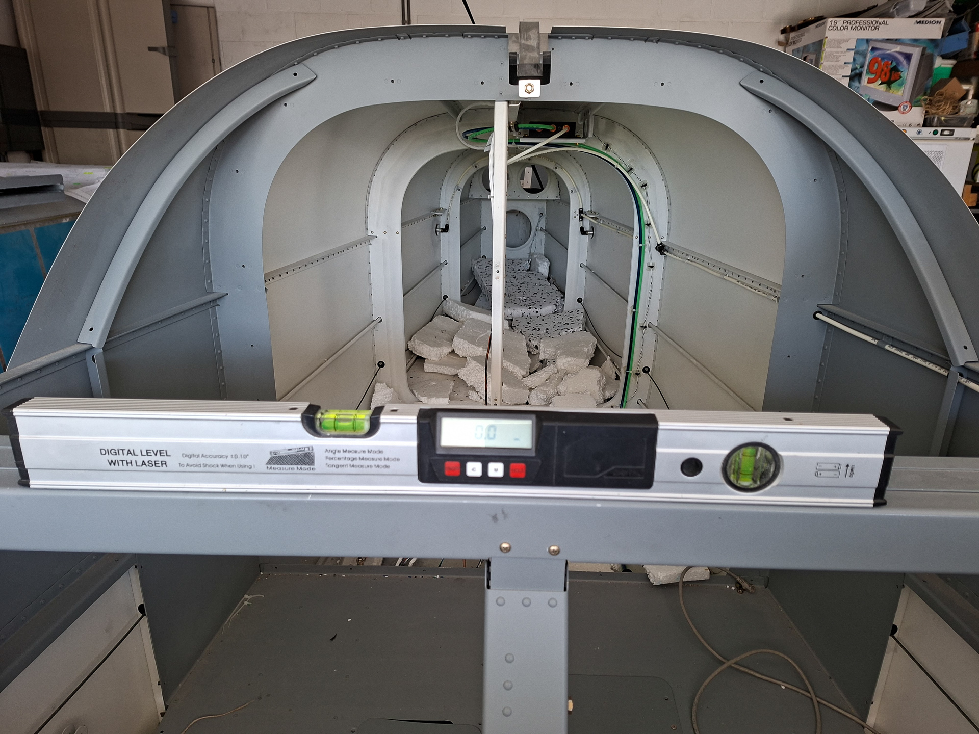
Task 1 is to make sure all your datum lines are absolutly level. This means you first make sure the airplane is level at 0 degrees both laterally and longitudinally.
Next to that, you also want to make sure the floor reference is level around the gear so that you have a common level measuring point relative to the longeron when aligning the wheel pants.
I'm kind of a geek when it comes to these things so I spent a lot of time getting everything in 0.0°.
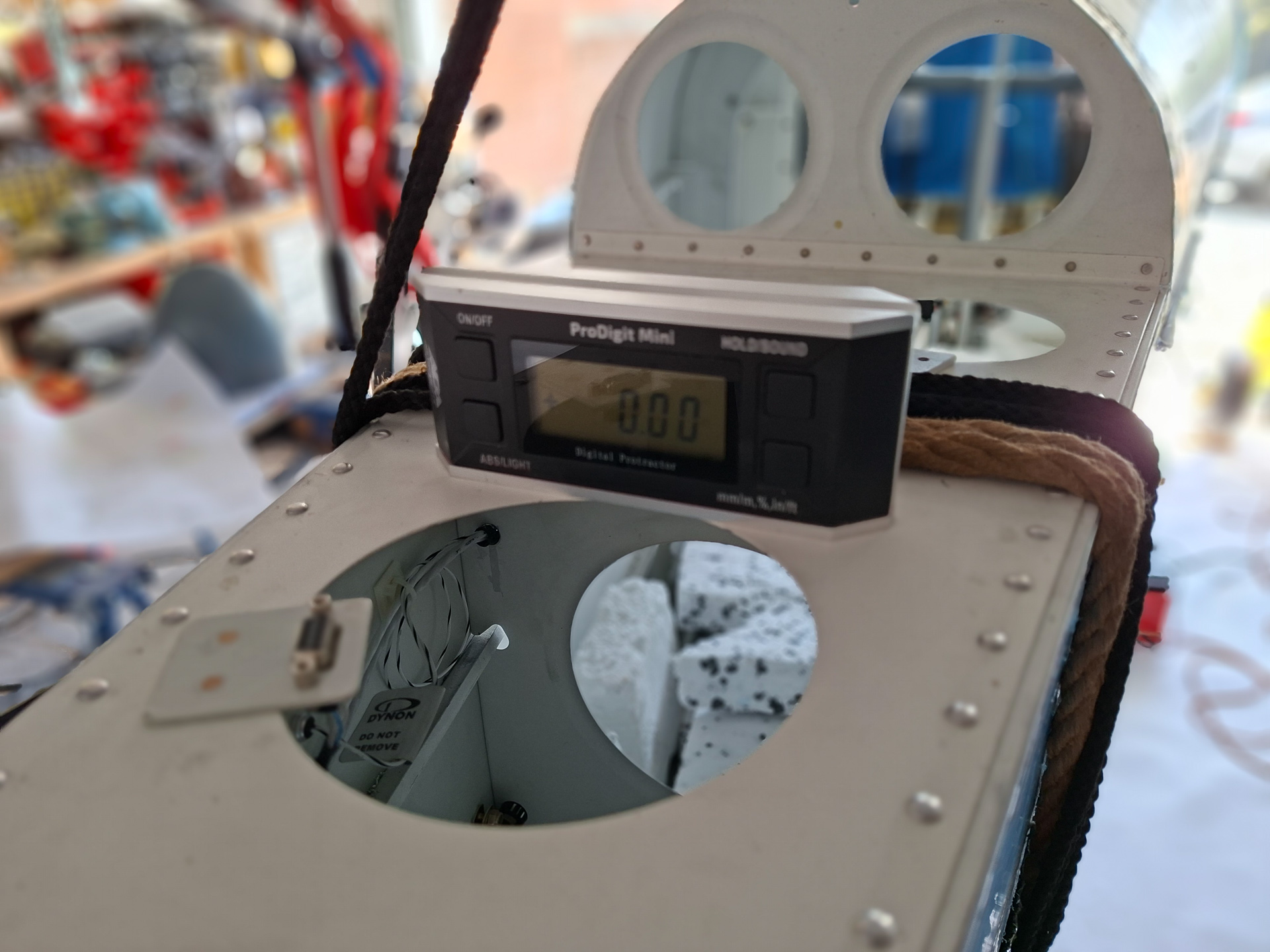
Below the image shows the ground plate is level. There is a small gap under the tyre so it's actually floating few millimeters off the ground

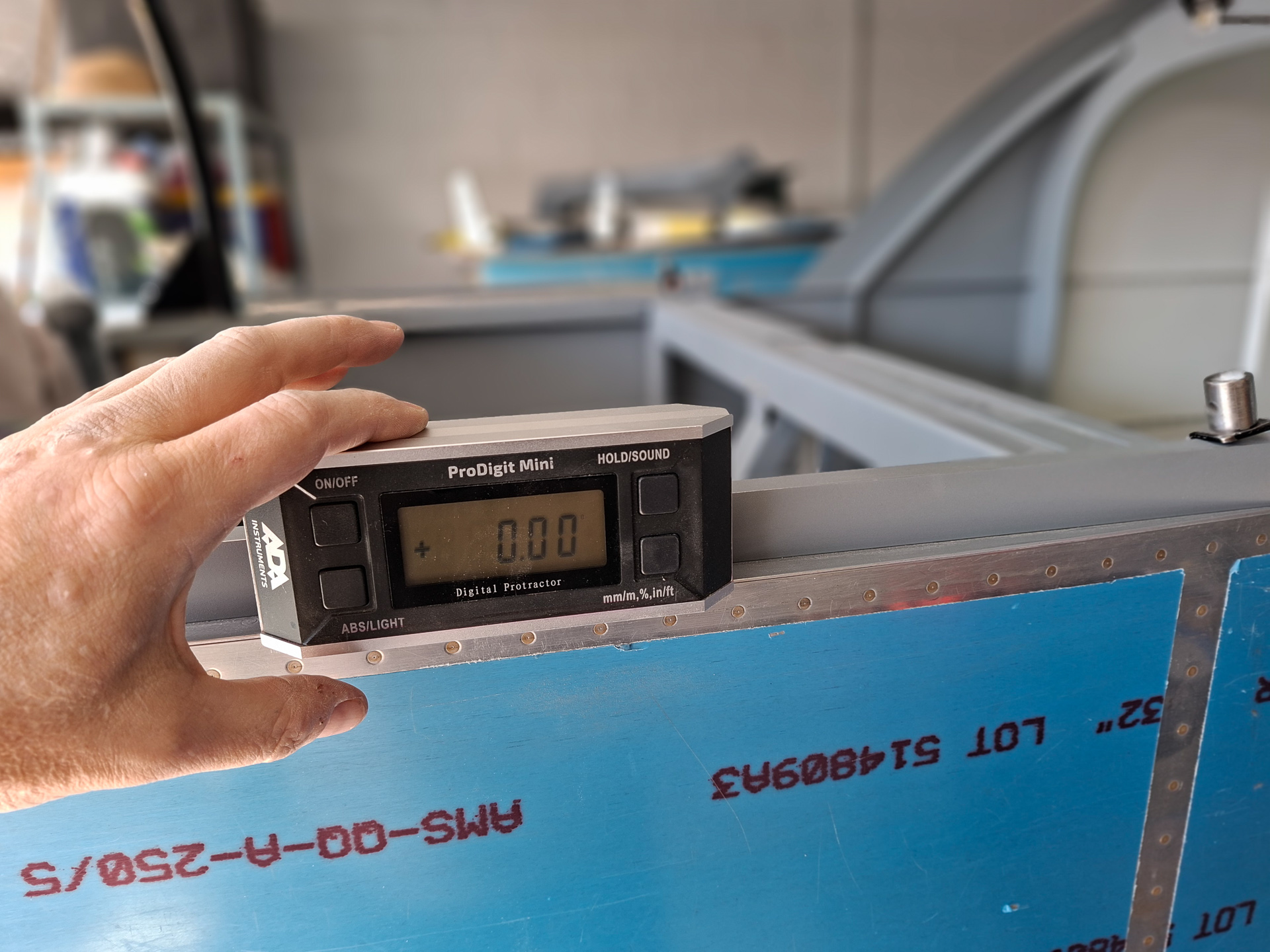
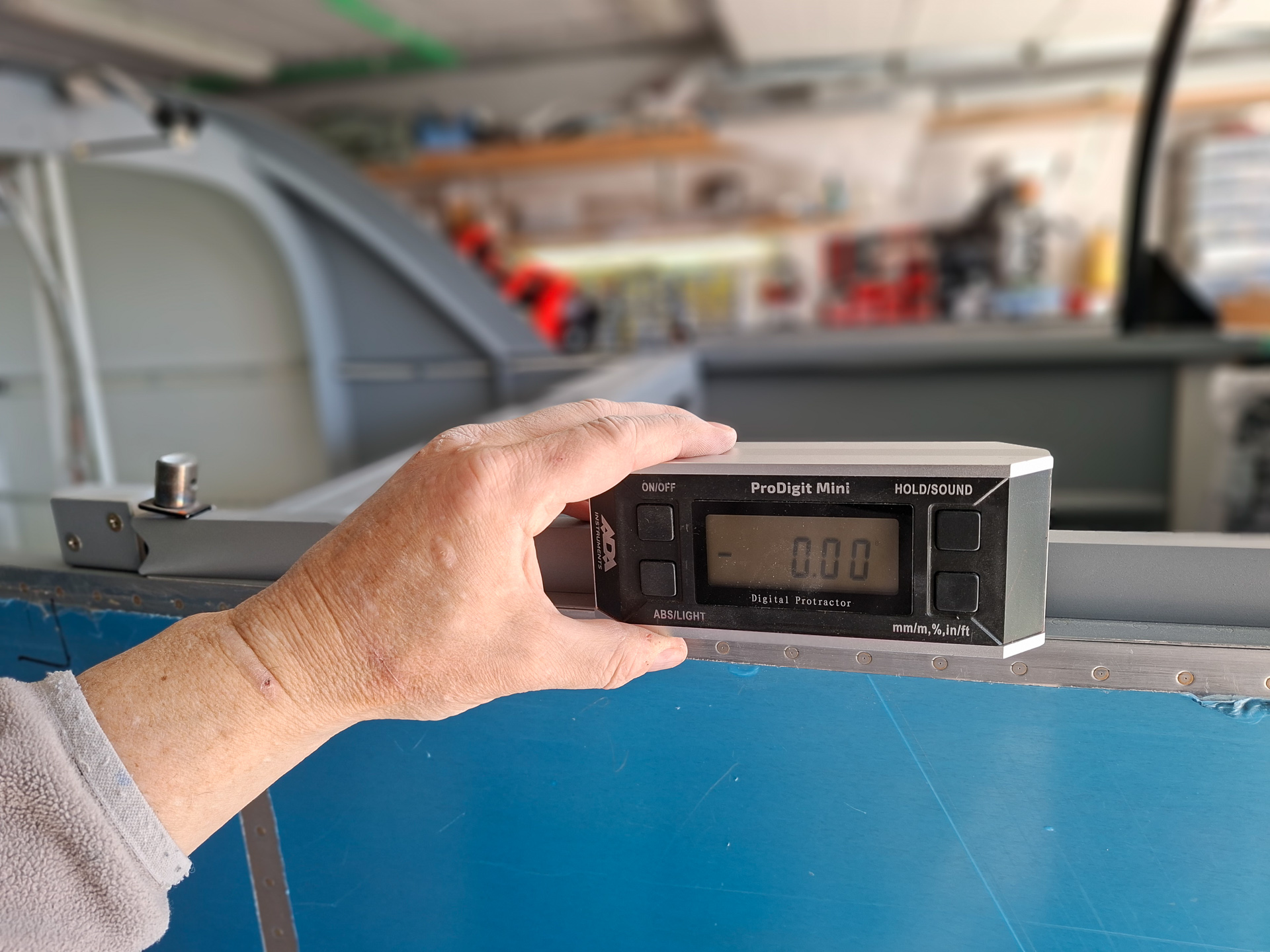
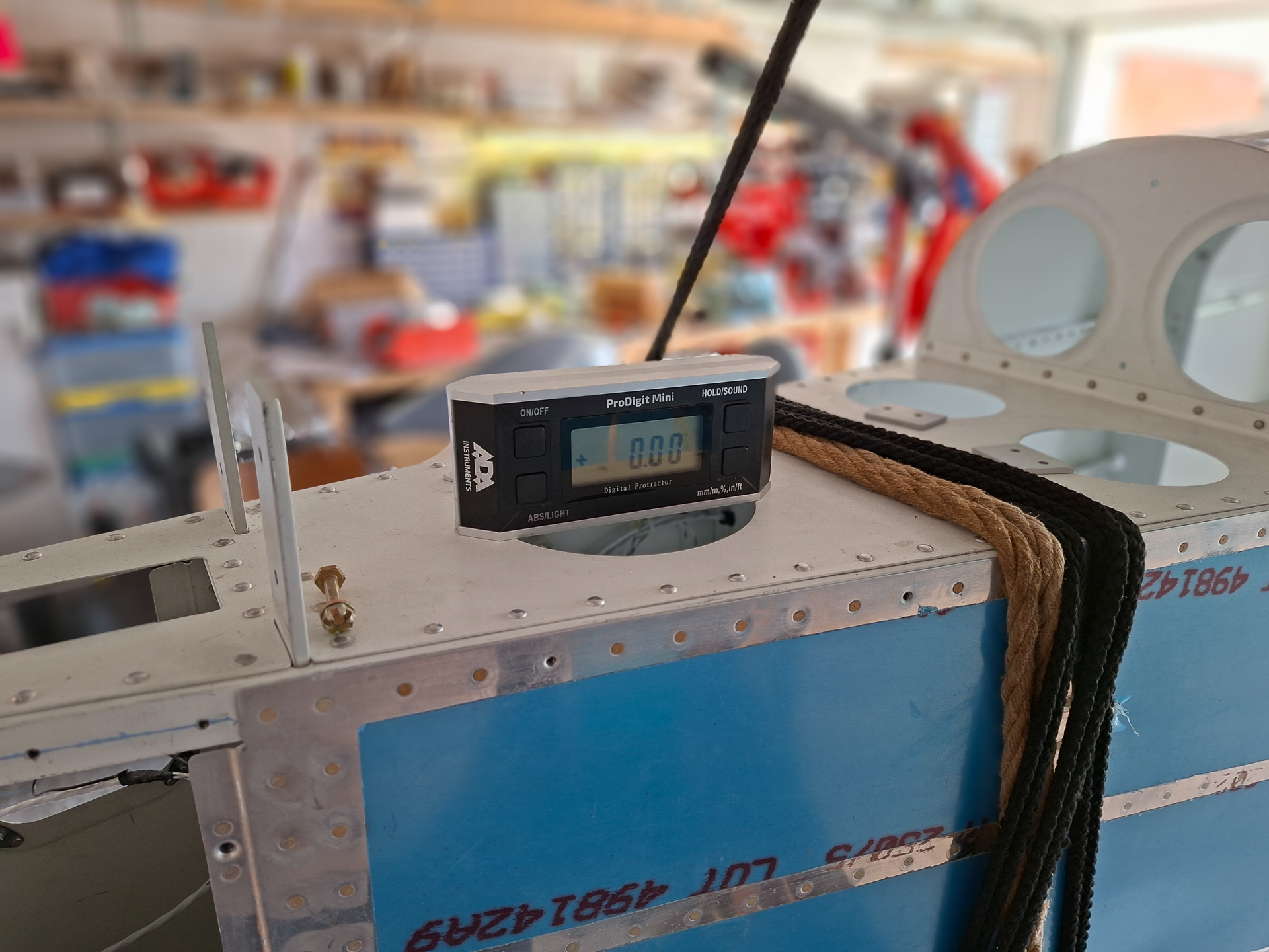
The F705 bulkhead is level
The F704 is level

Lengthwise, the longerons are level on both sides at all locations front, mid and rear fuselage and the rear deck is level.
Then I started squaring the U808 outer wheel pant bracket that attaches to the VA-106 wheel nut relative to the level ground plane (meaning also level to the longerons)
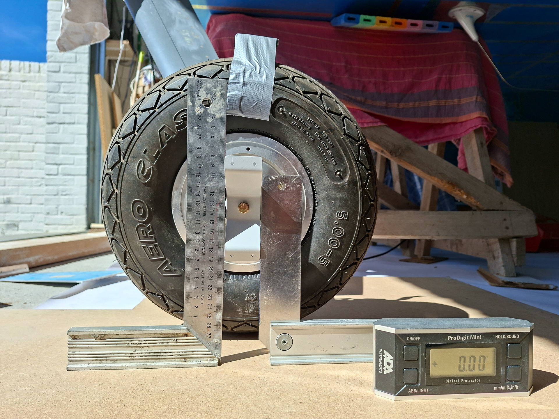
The manual has you place a 1 inch spacer on top of the center of the wheel. Good old duck tape holds the block in place. It's a little over an inch in my case.
Make sure you have drawn the centerline on top of the wheel pant. You want the center line mark aligned with the middle of the tyre. There is a rubber line on the tyre that makes that easy.
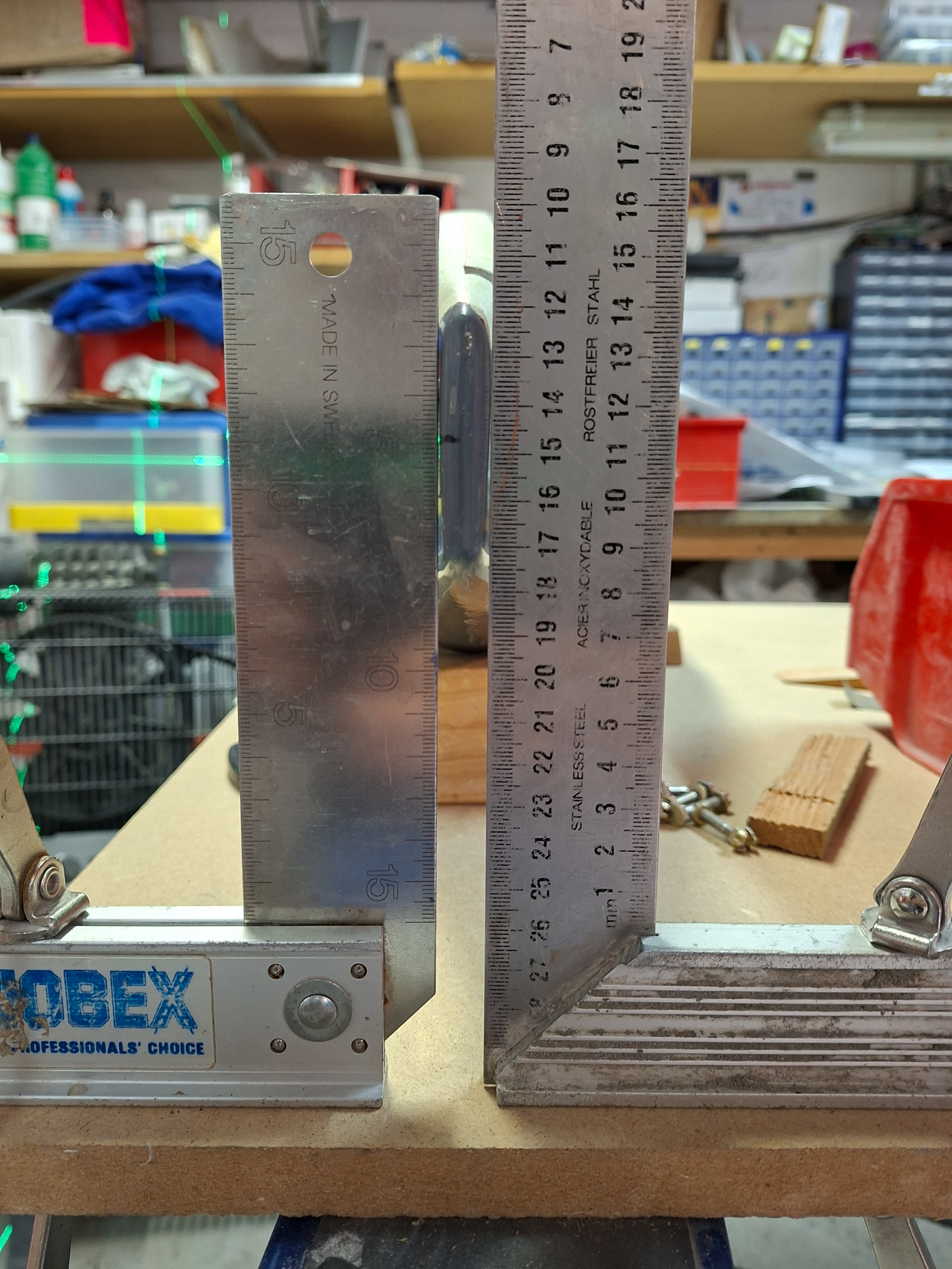
I decided that I wanted some form of reference also on the horizontal plane so I removed the pant again and clamped it with the back between two squares in order to draw a middle line.
The bottom of the wheel pant is uneven as it's still uncut so you may need to shim left or right to get the read sticking straight between the squares.
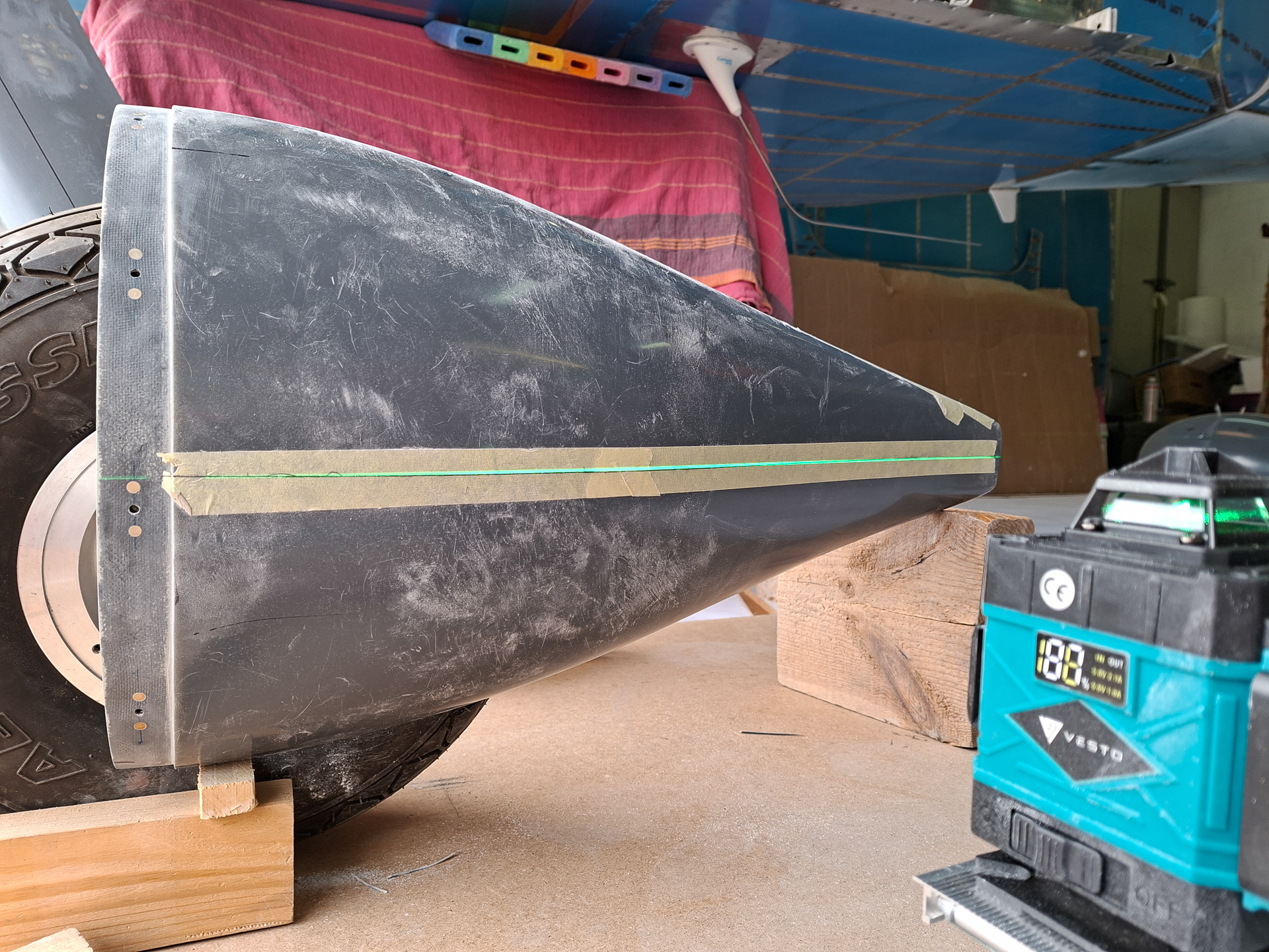
Then I used the laser level to find the middle line. I marked the middle of the tail of the wheel pant and then aligned the vertical line with the seperation line of the wheel pant. Moved the middle line up and checked where the line hit in the front.
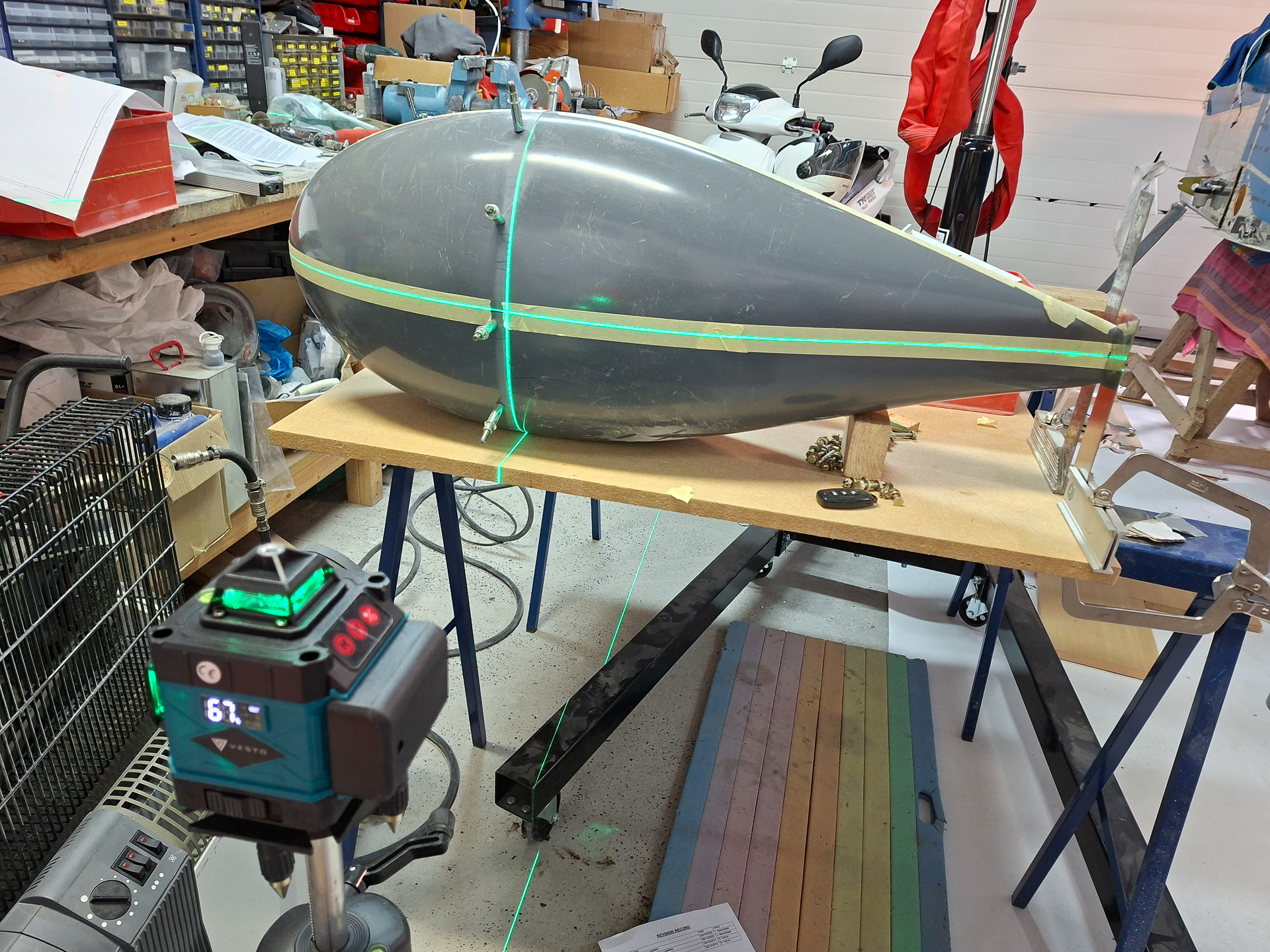
Here you see the vertical line aligned with the seperation line of the two parts. The horizontal line now is the middle line.
This will allow me now to measure on the front and the back to verify that height front and back to the middle line is equal distance.
It also helps seeing the horizontal line for level verification.

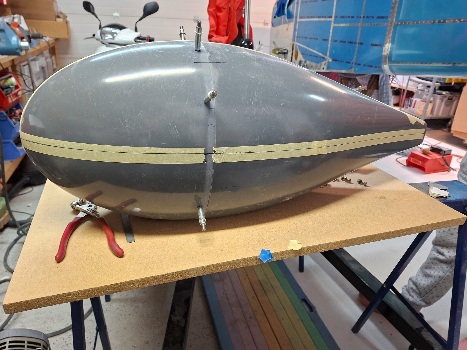
Transferred some points and connected the dots. Middle line done.
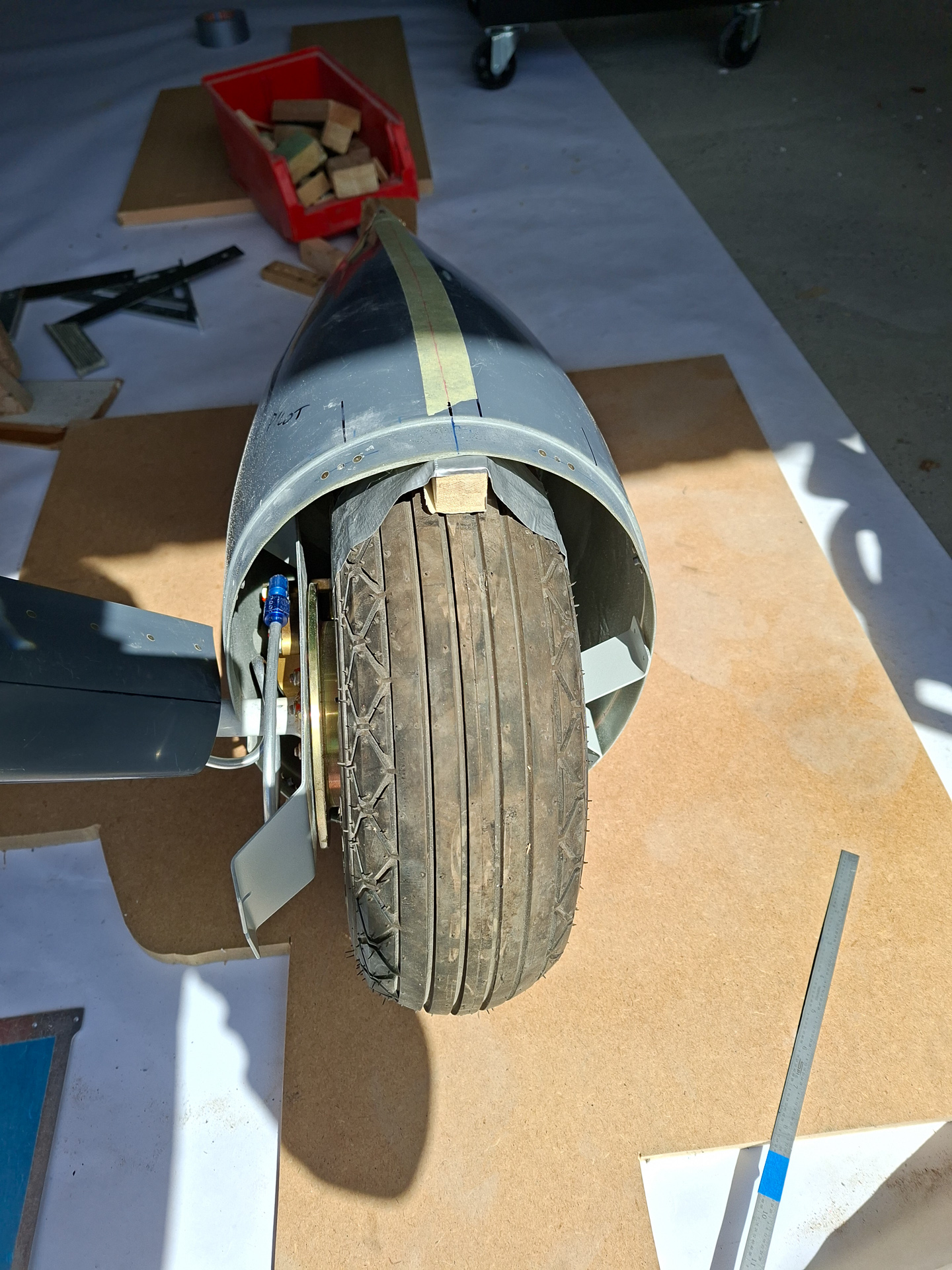
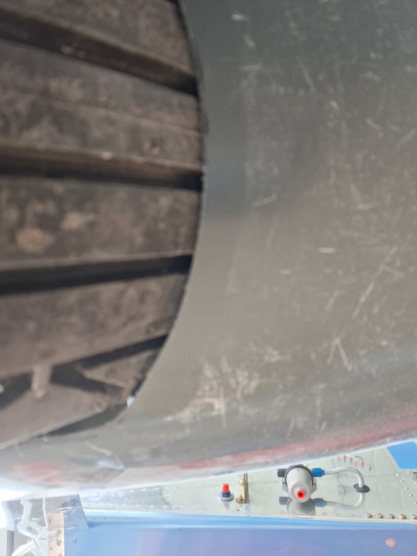
When I installed the wheel pant on the gear leg, this is how it showed up with the laser level.
I scratched my head trying to figure out why the line is not straight. and became frustrated by the sight.
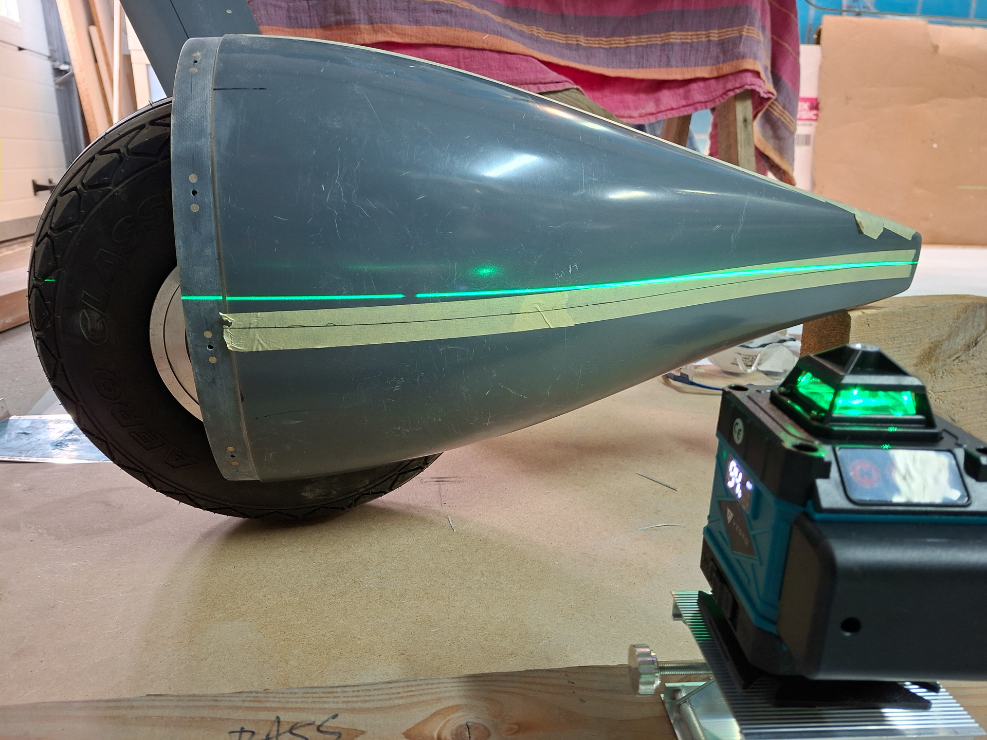
Checked the alignment of the leg fairing with the wheel pant. It's close to eachother but there is enough separation. I will keep it this way.
Moved the laser level again to find out that with movement of my laser, the line moves in various directions.
Only later that evening I found out my stupid thinking mistake.
The wheel is tilted inwards, that means that it's very normal. The laser is level and the wheel is tilted in , so it's very logical that the front and rear of the wheelpant look level , but the line joining them bends.
What I should actually do is define a tilt angle which is similar to the tilt angle of the tyre. (will do that by placing the level in front of the tyre and aligning the vertical line with the centerline of the tyre.
Then will move the laser level to the side using the same tilt angle and verify if the line then follows the horizontal line. Actually... this is even irrelevant. If the front and rear height are equal height, the wheel pant is level. But I'm being anal again and trying to confirm myself in various ways.
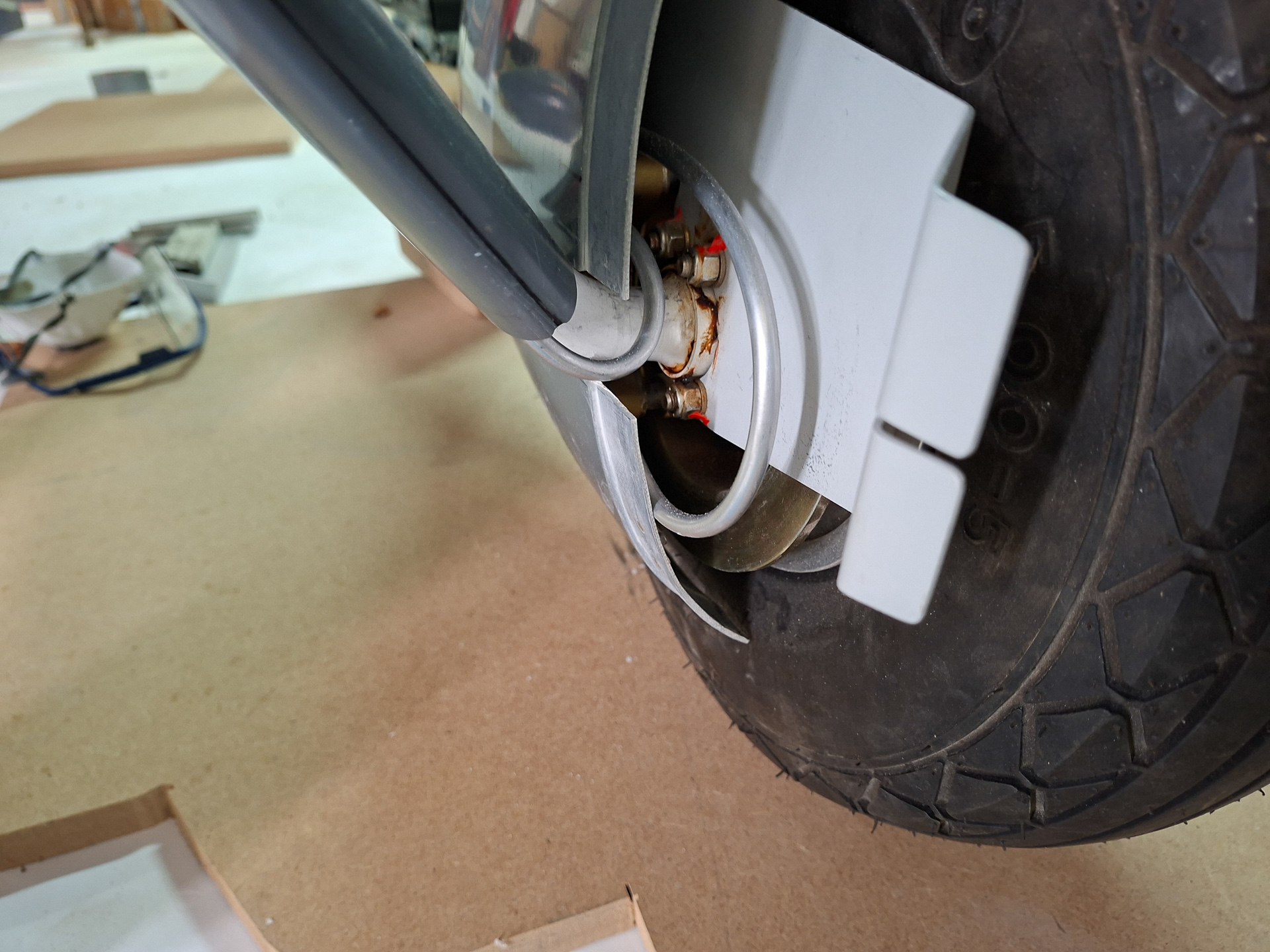
The wheel pant didn't quite move easily. Soon found out why... there will be a lot of cutting and filing going on at the bottom of the wheel pant.


